Elektron Analog Four Full Reference Manual
4 voice analog synthesizer
Hide thumbs
Also See for Analog Four:
- Getting started manual (21 pages) ,
- Full reference manual (131 pages)
Table of Contents
Advertisement
Quick Links
Advertisement
Table of Contents

Related Manuals for Elektron Analog Four


Summary of Contents for Elektron Analog Four
-
Page 2: Fcc Compliance Statement
FCC compliance statement This device complies with part 15 of the FCC rules. Operation is subject to the following two conditions: (1) This device may not cause harmful interference, and (2) this device must accept any interference received, including interference that may cause undesired operation. -
Page 3: Important Safety Instructions
Heed all warnings. unit is rack mounted. Follow all instructions. Do not put the PL-1 Protective Cover (Analog Four acces- Do not use this apparatus near water. sory) on the unit while the unit is powered on. Never use any aggressive cleaners on the casing or the LCD This product, either alone or in combination with an amplifier overlay. - Page 4 (claims must be presented to the carrier); repair or attempted repair by anyone other than Elektron or a certified Elektron repair center (b) any unit which has been altered or on which the serial number has been defaced, modified or removed; (c) normal wear and any periodic maintenance; (d) deterioration due to perspiration, corrosive atmosphere or other external causes such as extremes in temperature or humidity;...
-
Page 5: Table Of Contents
ANALOG FOUR SIGNAL PATH..................6 ABOUT THE COMPONENTS......................... 6 COMMENTS ON THE SIGNAL PATH ....................6 ABOUT THE OSCILLATORS AND FILTERS ..................6 OVERVIEW OF THE ANALOG FOUR STRUCTURE ............. 7 ABOUT THE DATA STRUCTURE ......................7 KIT ..............................7 SOUND.............................. 7 BANK .............................. - Page 6 THE CV TRACK..........................18 TRACK MUTING........................... 18 THE SEQUENCER ......................19 BASIC PATTERN OPERATIONS......................19 SELECTING A PATTERN ........................ 19 PATTERN CONTROL ........................19 TEMPO ............................20 PATTERN MODES..........................20 PATTERN RECORDING MODES......................20 TRIG TYPES............................ 20 GRID RECORDING MODE ......................21 LIVE RECORDING MODE ......................
- Page 7 PRODUCT DESIGN AND DEVELOPMENT ................... 44 ADDITIONAL DESIGN ........................44 FACTORY DEFAULT SOUND DESIGN ..................44 USER’S MANUAL..........................44 CONTACT INFORMATION........................44 ELEKTRON WEBSITE ........................44 DELIVERY ADDRESS........................44 TELEPHONE ........................... 44 APPENDIX A: SYNTH TRACK PARAMETERS OSCILLATOR 1 ............................1 OSCILLATOR 2 ............................
-
Page 9: Introduction
To make the most of the machine, we recommend you to carefully read this manual. Tutorial videos, found on the Elektron website, are also available. They cover the basics of the Analog Four and are a great complement to this document. CONVENTIONS IN THIS MANUAL In this manual we have used certain conventions. -
Page 10: The Background Of The Analog Four
We at Elektron owe a lot to analog technology. In fact, it is in our blood. The Sidstation, our first product, featured an analog filter which was decisive to the unique sound of the synth. With the Analog Four we return, in a sense, back to where we started. -
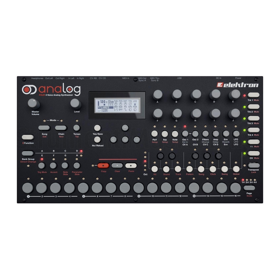
Page 11: Panel Layout And Connectors
PANEL LAYOUT AND CONNECTORS PANEL LAYOUT AND CONNECTORS FRONT PANEL 15 16 The Analog Four front panel. MASTER VOLUME sets the volume for the main outputs and the headphones output. [SONG] activates SONG mode. [CHAIN] activates CHAIN mode. LEVEL sets the overall volume level of the active track. Also used for scrolling in menus and setting various parameter values. -
Page 12: Rear Connectors
34. [FUNCTION] key. Press and hold for accessing secondary functions for some of the other keys. Secondary functions are where possible written in red text on the panel. REAR CONNECTORS The Analog Four rear connectors: Power on/off switch. 12 V DC power in. -
Page 13: Analog Four Accessories
If MIDI control of the Analog Four is desired, connect the MIDI OUT port of the device you wish send data from to the MIDI IN port of the Analog Four. The MIDI THRU port “echoes” the data arriving at the MIDI IN port, so it can be used for chaining MIDI units together. -
Page 14: Analog Four Signal Path
ANALOG FOUR SIGNAL PATH ANALOG FOUR SIGNAL PATH Below is an image outlining the signal path of the Analog Four. OSCILLATOR 1 SUB OSC AM AND SYNC MODES LEFT OSCILLATOR 2 LADDER FILTER MULTIMODE FILTER VCA/PAN OVERDRIVE SUB OSC RIGHT... -
Page 15: Overview Of The Analog Four Structure
Kits contain up to four Sounds, one for each synth track, as well as settings for the FX and CV tracks. The Analog Four can host 128 kits. A kit is always linked to a pattern. Read more in section “KITS AND SOUNDS” on page 12. -
Page 16: Chains
THE FX TRACK The FX track controls the Analog Four internal send effects. To edit the FX track, press the [TRACK 5] key. THE CV TRACK The CV track is used for controlling external equipment capable of receiving analog CV and Gate signals. To edit the CV track, press [TRACK 6]. -
Page 17: The User Interface
THE USER INTERFACE THE USER INTERFACE The center of Analog Four editing is the LCD display. The main interface screen is shown below: Bar indicating the overall volume level of the active track. The current tempo displayed with one decimal. -
Page 18: Quick Scrolling
THE USER INTERFACE QUICK SCROLLING In most menus quick scrolling is available. Press [FUNCTION] + the [UP] or [DOWN] arrow keys to move the cursor one menu page at a time. COPY, CLEAR AND PASTE Copy, clear and paste commands are available in a lot of contexts. A copy operation is performed by pressing [FUNCTION] + [REC]. -
Page 19: Quick Start
QUICK START QUICK START This quick start will guide you through some of the basic operations to allow you to start using the Analog Four right away. First connect it as described in section “CONNECTING THE UNIT”, on page 5. -
Page 20: Kits And Sounds
KITS AND SOUNDS Kits and Sounds are the basic building blocks of the Analog Four. They contain information about the parameter settings of the tracks. Kits can be regarded as a collection of Sounds as well as other settings. A Sound is essentially a synth track patch. -
Page 21: Performance Mode
KITS AND SOUNDS quickly scroll between the menu pages. Once a kit has been selected, press [YES/SAVE] to load it. The loaded kit will be linked to the active pattern. SAVE KIT is where all the current, kit related, settings can be saved as a kit. The saved kit will be linked to the active pattern. - Page 22 KITS AND SOUNDS PERFORMANCE CONFIGURE is where parameters are assigned to the performance mac- ros. After selecting this option, the list of performance macros and the knobs they are assigned to will show up. Use the [UP] and [DOWN] arrow keys to select the DATA ENTRY knob corresponding to the performance macro that should be edited.
-
Page 23: Sound Menu
KITS AND SOUNDS SOUND MENU In this menu individual Sounds are managed. Open the menu by pressing [FUNCTION] + [KEYBOARD D1]. Use the [UP] and [DOWN] arrow keys to move between the commands. Press [YES/SAVE] to confirm your selection. Exit the menu by pressing [NO/RELOAD]. LOAD TRACK SOUND opens a menu where one of the up to 128 saved Sounds can be loaded. -
Page 24: Playing A Sound
Both the VEL parameter of the NOTE menu and the velocity of incoming MIDI notes sent to the Analog Four from external devices will affect the assigned parameters. Open the menu by pressing [YES/SAVE]. Setting up the parameters work in the same way as setting up performance macros, covered on page 13. -
Page 25: Playing A Sound With A Midi Keyboard
FX and CV track parameter settings are only saved as part of a kit. THE FX TRACK The FX track controls the Analog Four internal send effects. To edit the FX track, press the [TRACK FX] key. Six PARAMETER pages exist for the FX track: EXT IN contains parameters relating to the external inputs. -
Page 26: The Cv Track
KITS AND SOUNDS REVERB controls the reverb effect. LFO contains parameters for the two LFOs that can modulate the FX track parameters. THE CV TRACK The CV track is used for controlling external equipment capable of receiving CV/Gate signals. To edit the CV track, press [TRACK CV]. -
Page 27: The Sequencer
THE SEQUENCER The sequencer of the Analog Four stores information in patterns. A pattern controls the playback of the synth, FX and CV tracks and various aspects of these tracks. Each of the 8 banks, ranging from A to H, can host 16 patterns, meaning 128 patterns are available. -
Page 28: Tempo
BPM will revert back to the original setting. • Tempo shift is very handy when manually syncing the Analog Four to a turntable or an external sound source. Note that you do not need to be in the TEMPO menu to perform tempo shifting. -
Page 29: Grid Recording Mode
LIVE RECORDING mode is the second method of adding trigs to the tracks. In this recording mode, the [KEY- BOARD] keys, or an external MIDI keyboard connected to the Analog Four, can be played in real time to input trigs to the tracks. It is also possible to enter parameter locks in real time. Trigs input in LIVE RECORDING mode will be placed on the sequencer in a micro timed fashion, meaning the µTM parameter in the NOTES... -
Page 30: Arpeggiator
THE SEQUENCER RELOAD PATTERN will reload the active pattern. It will either be reloaded to its original auto- saved state or to a specific saved state which can be determined by utilizing the SAVE PAT- TERN command. Press [NO/RELOAD] + [KEYBOARD F1] for a short cut to the RELOAD PATTERN command. -
Page 31: Arpeggiator Setup
THE SEQUENCER specified by the RNG setting the notes will be reset to their inital values. From there the octave transpose will be started all over again. LEG controls the legato of the arpeggiator. This setting will affect the note trigs of the track even if the MOD setting is set to OFF. -
Page 32: Notes Setup
THE SEQUENCER µTM controls the micro timing offset. A negative value will nudge the trig to a position before the quantized sequencer step, a positive after. Each micro timing value step is equal to one 1/ 384th of a 1/16 sequencer step. When entering note trigs in the LIVE RECORDING mode, they will automatically be micro timed. -
Page 33: Sound Locks
THE SEQUENCER types of tracks. Parameter locks can be removed by either performing a clear locks command, covered in sec- tion “COPY, PASTE AND CLEAR OPERATIONS” on page 28, or by simply removing the trig and entering it again. To apply parameter locks in GRID RECORDING mode, press and hold the [TRIG] key of a trig. Adjust the parameters you want to lock using the DATA ENTRY knobs. -
Page 34: Accent
THE SEQUENCER ACCENT Adding accent trigs is useful for quickly changing the volume and filter envelope behavior, or accentuation, for chosen steps of a track. Open the ACCENT menu by pressing [FUNCTION] + [BANK B/F]. Select the track that should be affected by pressing the corresponding [TRACK] key. Select the accent value by turning the LEVEL knob. -
Page 35: Parameter Slide
THE SEQUENCER PARAMETER SLIDE The PARAMETER SLIDE menu makes it possible for the parameter values of two separate note trigs or trigless locks of a track to slide between each other. Open the menu by pressing [FUNCTION] + [BANK D/H]. When this menu is active and [TRIG] keys are pressed, slide trigs will be placed on the sequencer. -
Page 36: Destructive Transpose
THE SEQUENCER If [FUNCTION] + [TRANSPOSE] are pressed, the transpose lock functionality will be activated. Transpose lock is indicated by a full-bright <TRANSPOSE> LED. When this function is activated, the [TRANSPOSE] key will act as if constantly pressed, enabling one-handed transpositions when pressing the [KEYBOARD] keys. •... -
Page 37: Track Menu
THE SEQUENCER To quick save a song, press [YES/SAVE] + [KEYBOARD G1]. The command is the same as the SAVE com- mand found in the SONG menu, covered on page 34. To quick reload a kit, press [NO/RELOAD] + [KEYBOARD C1]. This command is the same as the RELOAD KIT command found in the KIT menu, covered on page 12. -
Page 38: Click Track
THE SEQUENCER CLICK TRACK The CLICK TRACK menu controls the internal metronome of the Analog Four. Open the menu by pressing [FUNCTION] + [KEYBOARD A1]. Use the [UP]/[DOWN] arrow keys or the LEVEL knob to select in the list of settings. -
Page 39: Advanced Mode
A 2X time signature setting is useful for increasing the base resolution of the step sequencer to 32nd notes. A 3/4X setting is useful when the Analog Four is playing alongside other instruments set to the same BPM and you want the Analog Four to play triplets. -
Page 40: Chains And Songs
CHAINS AND SONGS CHAINS AND SONGS Chains are sequences consisting of several patterns. Chains and patterns can be used to form songs. 256 pattern entries are available to the 64 chains, meaning for example one chain can consist of 256 patterns or two chains can consist of 128 patterns each. -
Page 41: Song Edit Menu
CHAINS AND SONGS SONG EDIT MENU Songs are created in the SONG EDIT menu, which is accessed by pressing [FUNCTION] + [SONG]. Songs are played row by row, starting from the top and moving towards the bottom. If a song row contains a chain, all patterns in the chain will play before the song play position moves to the next row. -
Page 42: Song Menu
CHAINS AND SONGS SONG MENU In the SONG menu, songs can be saved, loaded renamed et cetera. Access the menu by pressing [FUNCTION] + [KEYBOARD G1]. RELOAD will reload the active song. It will be restored to its saved version. Press [NO/ RELOAD] + [KEYBOARD G1] for a short cut to this command. -
Page 43: Global Menu
GLOBAL MENU GLOBAL MENU The GLOBAL menu offers settings that affect the Analog Four on a global level. Global tune, MIDI and CV set- tings are made here. Up to four Global slots, where each can have individual settings, are available. -
Page 44: Midi Sync
• DISABLED will make the Analog Four disregard any incoming MIDI data. • MIDI will make the Analog Four listen only to MIDI data sent to the MIDI IN port. • USB will make the Analog Four listen only to MIDI data sent to the USB port. -
Page 45: Midi Channels
GLOBAL MENU • MIDI+USB will make the Analog Four listen to MIDI data sent to both the MIDI IN and USB ports. OUTPUT TO selects the destination to which the Analog Four will send MIDI data. • DISABLED will stop the Analog Four from sending out any MIDI data. -
Page 46: Cv Config
GLOBAL MENU CV CONFIG Here the CV/Gate output signals are controlled. CV A-D CONFIG Each of the subpages are identical and one for each CV/Gate output exists. The list of available parameters in this menu will depend on the menu settings. By pressing [FUNCTION] + [CV A-D] this menu will be opened for the corresponding CV/Gate output. -
Page 47: Sysex Dump
[UP]/[DOWN] or the LEVEL knob. Press [YES/SAVE] to open the highlighted menu selec- tion. When receiving or sending SysEx data, the MIDI ports or the USB port of the Analog Four should be connected to the external sending/receiving device. If the external device is a computer, we recommend using our free SysEx utility C6, which can be downloaded from the Elektron website. -
Page 48: Sysex Receive
Use the [UP]/[DOWN] keys or the LEVEL knob to select what should be received. Press [YES/SAVE] to initiate the SysEx receive procedure. The Analog Four will start listening to incoming data. Press [NO/RELOAD] to stop listening. -
Page 49: Os Upgrade
When performing the sending of the OS syx file, we recommend using our free SysEx utility C6. It can be downloaded from the Elektron website. • If the Analog Four is receiving the OS upgrade through the MIDI ports, use the Elektron TM-1 USB MIDI interface for up to 10x transfer speeds. -
Page 50: Early Startup Menu
TEST MODE To enter this mode, press the first [TRIG] key. If you have any trouble with your Analog Four and suspect it may be due to a hardware problem, perform this self test. No errors should be reported as shown below. If that is not the case, contact Elektron support or the retailer you bought the Analog Four from. -
Page 51: Technical Information
TECHNICAL INFORMATION TECHNICAL INFORMATION SPECIFICATIONS THE SEQUENCER ELECTRICAL SPECIFICATIONS 4 synth tracks Impedance balanced audio outputs: 1 FX track Ω Headphones out level: +19 dBu (55 1 CV/Gate track Main outputs level: +19 dBu 128 patterns Ω Up to 64 steps per pattern Output impedance: 440 unbalanced 128 Sounds... -
Page 52: Credits And Contact Information
FACTORY DEFAULT SOUND DESIGN Jimmy Myhrman Jon Mårtensson Daniel Troberg Cenk Sayinli USER’S MANUAL Thomas Ekelund Jon Mårtensson CONTACT INFORMATION ELEKTRON WEBSITE http://www.elektron.se DELIVERY ADDRESS Elektron Music Machines MAV AB Sockerbruket 9 SE-414 51 Gothenburg Sweden TELEPHONE +46 (0)31 743 744 0... -
Page 53: Appendix A: Synth Track Parameters
Appendix A: SYNTH TRACK PARAMETERS In this appendix, the parameters of the synth tracks are explained. OSCILLATOR 1 The OSC1 pages control the first oscillator, its suboscillator, plus the noise generator. OSC 1 (page 1) NOISE (page 2) TUN (OSC1 Coarse Tune) sets the pitch of the oscillator in semi- TUN (Noise Tune) sets the tuning of the noise spectrum. -
Page 54: Oscillator 2
OSCILLATOR 2 The OSC2 pages control the second oscillator and the accompanying suboscillator. Settings that will affect both oscillators are found here as well. OSC 2 (page 1) OSC (page 2) TUN (OSC2 Coarse Tune) sets the pitch of the oscillator in semi- AM1 (Osc1 AM) engages Amplitude Modulation on Oscillator 1, tones. -
Page 55: Filters
FILTERS In the FILTERS page, settings that will affect the two track filters are found. FILTERS FRQ (Filter1 Frequency) controls the cutoff frequency of Filter 1, the 4-pole lowpass transistor ladder filter. Frequencies above the cutoff get damped while frequencies below pass through the fil- ter. -
Page 56: Amplitude
AMPLITUDE The AMP page contains settings for the amplitude envelope and the effects sends, as well as panning and volume of the sound. ATK (EnvA Attack) controls the attack time of the EnvA enve- lope, which controls the amplitude of the track. DEC (EnvA Decay) controls the decay time of the EnvA enve- lope. -
Page 57: Envelopes
ENVELOPES Here parameters controlling the two assignable envelopes are found. The first envelope, ENVF, is hard- linked to the cutoff parameters of the two filters but can also modulate two user-selectable destinations. ENVF (page 1) ENV2 (page 2) ATK (EnvF Attack) controls the attack time of the EnvF enve- ATK (Env2 Attack) controls the attack time of the Env2 envelope. -
Page 58: Lfo
The two track LFOs can be used to modulate the other synth track parameters. LFO1 (page 1) LFO2 (page 2) SPD (LFO1 Speed) controls the speed of LFO1. It is synced to SPD (LFO2 Speed) controls the speed of LFO2. It is synced to the BPM. -
Page 59: Appendix B: Fx Track Parameters
Appendix B: FX TRACK PARAMETERS In this appendix, the parameters of the external input page and the three send effects are explained. EXTERNAL IN The EXT IN page controls the signal path from the two audio inputs to the main mixer. These external signals can be routed to the effects and panned just like the four synth tracks. -
Page 60: Wideshift Chorus
WIDESHIFT CHORUS The Wideshift Chorus can be used to widen sounds, enhance the stereo image or add subtle movement to sounds. CHORUS PRE (Predelay) controls the predelay time of the Wideshift Cho- rus. SPD (Speed) sets the low frequency modulation speed of the chorus taps. -
Page 61: Saturator Delay
SATURATOR DELAY The Saturator Delay adds an echo-like effect to the audio. Thanks to the special features of this effect, it can also be used to subtly warm or severely distort the delay signal. DELAY TIM (Time) sets the delay time. It is relative to the current BPM and is measured in 128th notes. -
Page 62: Supervoid Reverb
SUPERVOID REVERB The Supervoid Reverb is perfect for positioning sounds in the mix.It can simulate everything from vast locations to small spaces. REVERB PRE (Predelay) controls the predelay time of the Supervoid Reverb. DEC (Decay Time) sets the decay time of the reverberated sig- nal, essentially setting the size of the room. -
Page 63: Fx Lfo
FX LFO The FX LFO menu consists of two LFOs dedicated to modulating FX track parameters. LFO1 (page 1) LFO2 (page 2) SPD (LFO1 Speed) controls the speed of LFO1. It is synced to SPD (LFO2 Speed) controls the speed of LFO2. It is synced to the BPM. - Page 64 Appendix B: FX TRACK PARAMETERS...
-
Page 65: Appendix C: Cv Track Parameters
Appendix C: CV TRACK PARAMETERS In this appendix, the CV/Gate track parameters are explained. CV A-D The CV A-D pages control the signals sent from the 2 dual CV/Gate outputs. Depending on the CV type chosen in the CV CONFIG menu, the available parameters will change. TUN (Coarse Tune) sets the coarse tuning of the CV in semi- tones. -
Page 66: Cv Envelopes
CV ENVELOPES Here parameters controlling the two assignable CV envelopes are found. The CV envelopes can modulate parameters found on the CV track. They can also be sent to the CV/Gate outputs, by setting up a CV channel's type as VALUE LIN. ENV1 (page 1) ENV2 (page 2) ATK (Env1 Attack) controls the attack time of the Env1 envelope. -
Page 67: Cv Lfo
CV LFO The two CV LFOs can be used to modulate other CV track parameters. They can also be sent to the CV/Gate outputs, by setting up a CV channel's type as VALUE LIN and then letting the LFO modulate its VAL parameter. LFO1 (page 1) LFO2 (page 2) SPD (LFO1 Speed) controls the speed of LFO1. - Page 68 Appendix C: CV TRACK PARAMETERS...
-
Page 69: Appendix D: Midi
Appendix D: MIDI In this appendix, the MIDI CC and NRPN implementation is covered. PERFORMANCE PARAMETERS The following messages affect the performance parameters on all tracks. They are also sent when adjusting the knobs controlling the parameters. PERFORMANCE NRPN Parameter Encoder NRPN MSB NRPN LSB... - Page 70 SYNTH TRACK PARAMETERS The following messages affect the synth track parameters. They are also sent when adjusting the knobs controlling the parameters. OSC 1 NRPN Parameter Encoder NRPN MSB NRPN LSB Data Range MSB Data Range LSB Pitch 0-127 0-127 0-127 Detune 0-127...
- Page 71 NOISE CC Parameter Encoder CC MSB CC LSB Data Range MSB Data Range LSB Noise S&H 0-127 0-127 Noise Fade 0-127 0-127 Noise Level 0-127 0-127 0-127 0-127 0-127 0-127 OSC 2 NRPN Parameter Encoder NRPN MSB NRPN LSB Data Range MSB Data Range LSB Pitch 0-127...
- Page 72 OSC COMMON NRPN Parameter Encoder NRPN MSB NRPN LSB Data Range MSB Data Range LSB OSC1 AM 0-127 Sync Mode 0-127 Sync Amount 0-127 Bend Amount 0-127 Slide Time 0-127 OSC2 AM 0-127 Note Sync 0-127 Vibrato Fade 0-127 Vibrato Speed 0-127 Vibrato Depth 0-127...
- Page 73 FILTERS CC Parameter Encoder CC MSB CC LSB Data Range MSB Data Range LSB Filter1 Frequency 0-127 0-127 Filter1 Resonance 0-127 Filter Overdrive 0-127 Filter1 Keytracking 0-127 Filter1 Envelope Amount 0-127 Filter2 Frequency 0-127 0-127 Filter2 Resonance 0-127 Filter2 Type 0-127 Filter2 Keytracking 0-127...
- Page 74 ENVF NRPN Parameter Encoder NRPN MSB NRPN LSB Data Range MSB Data Range LSB EnvF Attack Time 0-127 EnvF Decay Time 0-127 EnvF Sustain Level 0-127 EnvF Release Time 0-127 EnvF Env Shape 0-127 EnvF Gate Length 0-127 EnvF Destination A 0-127 EnvF Depth A 0-127...
- Page 75 ENV2 CC Parameter Encoder CC MSB CC LSB Data Range MSB Data Range LSB Env2 Attack Time 0-127 Env2 Decay Time 0-127 Env2 Sustain Level 0-127 Env2 Release Time 0-127 Env2 Env Shape 0-127 Env2 Gate Length 0-127 Env2 Destination A 0-127 Env2 Depth A 0-127...
- Page 76 LFO2 NRPN Parameter Encoder NRPN MSB NRPN LSB Data Range MSB Data Range LSB LFO2 Speed 0-127 LFO2 Speed Multiplier 0-127 LFO2 Fade 0-127 LFO2 Start Phase 0-127 LFO2 Mode 0-127 LFO2 Waveform 0-127 LFO2 Destination A 0-127 LFO2 Depth A 0-127 0-127 LFO2 Destination B...
- Page 77 FX TRACK PARAMETERS The following messages affect the FX track parameters. They are also sent when adjusting the knobs controlling the parameters. EXT IN Parameter Encoder NRPN MSB NRPN LSB Data Range MSB Data Range LSB Ch1 Chorus Send 0-127 0-127 Ch1 Delay Send 0-127...
- Page 78 REVERB Parameter Encoder NRPN MSB NRPN LSB Data Range MSB Data Range LSB Predelay 0-127 0-127 Decay Time 0-127 Shelving Freq 0-127 Shelving Gain 0-127 0-127 HP Filter 0-127 LP Filter 0-127 0-127 0-127 Send Level 0-127 LFO1 Parameter Encoder NRPN MSB NRPN LSB Data Range MSB...
- Page 79 CV TRACK PARAMETERS The following messages affect the CV track parameters. They are also sent when adjusting the knobs controlling the parameters. CV A Parameter Encoder NRPN MSB NRPN LSB Data Range MSB Data Range LSB CV A Tune 0-127 0-127 0-127 CV A Value...
- Page 80 Parameter Encoder NRPN MSB NRPN LSB Data Range MSB Data Range LSB CV D Tune 0-127 0-127 0-127 CV D Value 0-127 CV D Clock 0-127 CV D Source 0-127 0-127 0-127 0-127 0-127 0-127 ENV1 Parameter Encoder NRPN MSB NRPN LSB Data Range MSB Data Range LSB...
- Page 81 LFO1 Speed 0-127 LFO1 Speed Multiplier 0-127 LFO1 Fade 0-127 LFO1 Start Phase 0-127 LFO1 Mode 0-127 LFO1 Waveform 0-127 LFO1 Destination 1 0-127 LFO1 Depth 1 0-127 LFO1 Destination 2 0-127 LFO1 Depth 2 0-127 LFO2 Parameter Encoder NRPN MSB NRPN LSB Data Range MSB Data Range LSB...
- Page 82 Appendix D: MIDI...
-
Page 83: Index
INDEX Synth config SysEx dump GRID RECORDING MODE 21 ACCENT 26 KITS 12 ACCESSORIES Clear kit Carrying bag and protective lid Load kit Rack mount kit Performance mode ARPEGGIATORS 22 Reload kit Arpeggiator setup Save kit CALIBRATION 35 LCD SCREEN 9 CHAINS 32 LEGATO MODE 15 CLICK TRACK 30... - Page 84 PARAMETER LOCKS 24 Grid recording mode PARAMETER SLIDE 27 Live recording mode PATTERN MODES 20 Direct jump SAVING Direct start Kits Sequential Patterns PATTERNS 19 Songs Copy Sounds Copy track Track Copy track page SCALE SETUP Copy trig Advanced Grid recording mode Normal Live recording mode SONGS 32...
- Page 85 Note slide Parameter lock Parameter slide Sound lock Trig mute Trigless lock USER INTERFACE 9 INDEX...
- Page 86 INDEX...
Need help?
Do you have a question about the Analog Four and is the answer not in the manual?
Questions and answers