Table of Contents
Advertisement
Quick Links
Advertisement
Chapters
Table of Contents

Related Manuals for Elektron Syntakt


Summary of Contents for Elektron Syntakt
- Page 1 Syntakt User Manual...
- Page 2 Elektron may also make improvements and/or changes in the products and programs described in this document at any time without notice. In no event shall Elektron be liable for any special, indirect, or consequential damages or any damages whatsoever resulting from loss of use, data, or profits, whether in an action of contract, negligence, or other action, arising out of or in connection with the use or performance of this information.
- Page 3 • Do not exceed the limitations specified in the Electrical specifications. SOUND PEAKS • A brief signal will be sent to all audio outputs of the Syntakt when the Test mode on the STARTUP Menu is activated. Remember to turn down the volume on all speakers and headphones before activating Test mode.
-
Page 4: Table Of Contents
5.4.1 ANALOG FX BLOCK ROUTING ............. 18 6. OVERVIEW OF THE SYNTAKT DATA STRUCTURE ......19 6.1 +DRIVE . - Page 5 7.15.1 BACKING UP PROJECTS AND SOUNDS ........... 26 7.15.2 TRANSFERRING BACKED UP FILES TO YOUR ELEKTRON DEVICE ......26 8.
- Page 6 TABLE OF CONTENTS 9.11 SONG MODE ................45 9.11.1 THE SONG EDIT SCREEN .
- Page 7 16.1 SYNTAKT WITH A MONOPHONIC BASS MACHINE ........
- Page 8 TABLE OF CONTENTS A.4 ANALOG CYMBAL MACHINES ............101 APPENDIX B: MIDI .
-
Page 10: Introduction
1. INTRODUCTION 1. INTRODUCTION Thank you for purchasing Syntakt. The Syntakt is a compact drum computer and synthesizer from Elektron. It contains all the necessary tools to make people move to the music. A digital and highly flexible sound engine, an analog fx block with multi-mode filter and drive, a live-friendly sequencer, the means to control external MIDI gear, and Overbridge support. -
Page 11: The Syntakt
Now is the time. You sit at your sonic workspace and turn on the Elektron Syntakt. It breathes into life, and the glint of red light spirits you into action. Analog synthesis meets digital synthesis. A musical cyborg companion. -
Page 12: Panel Layout And Connectors
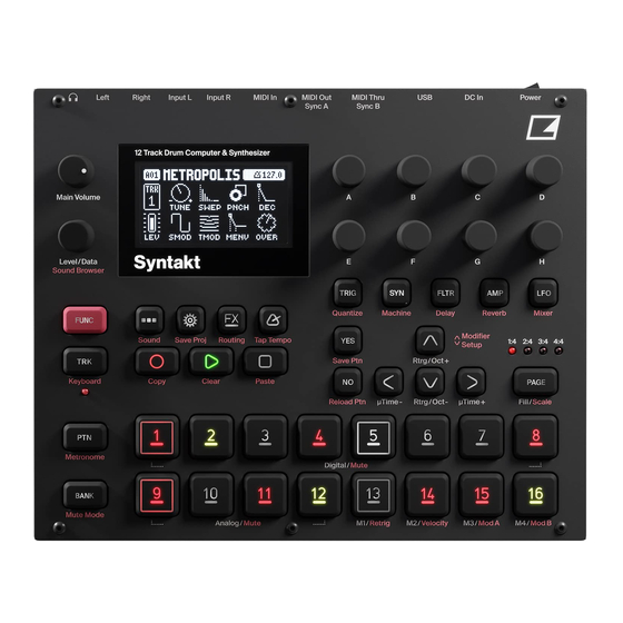
3. PANEL LAYOUT AND CONNECTORS 3. PANEL LAYOUT AND CONNECTORS 3.1 FRONT PANEL Left Right Input L Input R MIDI In MIDI Out MIDI Thru DC In Power Sync A Sync B 12 Track Drum Computer & Synthesizer Main Volume Level/Data Sound Browser TRIG... - Page 13 20. [FUNC] key. Press, hold and press another key to access the secondary function of that key. The sec- ondary functions are written in red on the Syntakt front panel. 21. LEVEL/DATA sets the overall volume level of the active track. It is also used for setting parameters and...
-
Page 14: Rear Connectors
USB connector of the Syntakt. 4. If you want to use MIDI to control the Syntakt, connect the MIDI OUT port of the device you wish to send data from to the MIDI IN port of the Syntakt. The MIDI THRU port duplicates the data arriving at the MIDI IN port, so it can be used for chaining MIDI units together. -
Page 15: Quick Start
4. QUICK START If you are the kind of person who just wants to dig into your Elektron device and start making noise, this section is for you. This quick start will guide you through some of the basic operations to begin using the Syntakt. -
Page 16: Editing Parameters
4. QUICK START 4.5 EDITING PARAMETERS Each track has five PARAMETER pages. Press [PARAMETER] keys TRIG, SYN, FLTR, AMP, and LFO to access the different PARAMETER pages. These parameters affect the sound and signal in various ways. 1. Make sure a pattern is playing. 2. -
Page 17: Syntakt Sound Architecture
5. SYNTAKT SOUND ARCHITECTURE ANALOG VOICE MULTIMODE OVERDRIVE The illustrations below show the Syntakt sound architecture, with its analog and digital voice types and send SOUND OUTPUT FILTER GENERATOR effects. The illustrations also show what components of the sound architecture are analog (grey boxes) or ANALOG digital (white boxes). -
Page 18: Analog Fx Block Routing
5. SYNTAKT SOUND ARCHITECTURE 5.4.1 ANALOG FX BLOCK ROUTING Press [FUNC] + [FX] to open the ANALOG FX BLOCK ROUTING menu. In the ANALOG FX BLOCK ROUTING menu, you can select which tracks, send effects, and the external in, you want to route through the analog FX block (orange [TRIG] key) or directly to the main mix (dim orange [TRIG] key). -
Page 19: Overview Of The Syntakt Data Structure
A project contains 128 patterns. General settings and states are also stored in the project. When a project is loaded it becomes the active working state of the Syntakt. From here it is possible to edit the patterns and sounds of the project. Every time the Syntakt is switched on, it boots to the active working state, the active project. -
Page 20: Midi Tracks
6.3.2 MIDI TRACKS You can change any track on the Syntakt from being an audio track to instead be used as a MIDI track, meaning you can have up to twelve MIDI tracks. The MIDI tracks are used to control external, MIDI- equipped gear. -
Page 21: Interacting With The Syntakt
7. INTERACTING WITH THE SYNTAKT 7. INTERACTING WITH THE SYNTAKT The screen shows all the information needed for real-time interaction and editing on the Syntakt. The eight DATA ENTRY knob parameters shown will vary depending on the given situation. Below is the main inter- face screen of the SYN page. -
Page 22: Parameter Editing
7. INTERACTING WITH THE SYNTAKT 7.5 PARAMETER EDITING The DATA ENTRY knobs are used to change the values of the track parameters. The positions of the pa- rameters on the screen correspond to the physical locations of the knobs on the front panel. Some of the parameters on the screen tell you what DATA ENTRY knob controls that particular parameter. -
Page 23: Pop-Up Naming
7. INTERACTING WITH THE SYNTAKT The [LEFT] and [RIGHT] arrow keys are used to navigate between the characters. Turning the LEVEL/ DATA knob or pressing the [UP] or [DOWN] arrow keys selects the characters. [FUNC] + [NO] erases characters. [FUNC] + [YES] inserts space. Press and hold [FUNC] to access the Pop-up Naming menu. -
Page 24: Mute Mode
7. INTERACTING WITH THE SYNTAKT KB SCALE sets the track’s scale. This setting governs which notes are playable on the Syntakt’s [TRIG] keys to allow only notes in the set scale. For a list of all selectable keyboard scales, please see “APPEN- DIX E: KEYBOARD SCALES”... -
Page 25: Trig Modifiers
Some functions on the Syntakt can be triggered by sending MIDI note values from an external MIDI device (a MIDI keyboard or a computer, for example) connected to the Syntakt via a standard MIDI cable or a USB 2.0 A to B connector cable. -
Page 26: Overbridge
MIDI program change messages 0–127 will select pattern 1–128 (A01–H16) on the Syntakt. Additionally, MIDI CC and NRPN messages can be sent to control various aspects of the Syntakt. For more information, please see “APPENDIX B: MIDI” on page 108. - Page 27 7. INTERACTING WITH THE SYNTAKT 4. On the top right side, in the drop-down menu, select the type of file you want to transfer. 5. On the top left side, in the drop-down menu, make sure “MY COMPUTER” is selected.
-
Page 28: Patterns And Sounds
8. PATTERNS AND SOUNDS The patterns are the primary data container for the Syntakt. Sixteen patterns are available for each of the eight banks, which means that 128 patterns are available for each project. A pattern contains up to twelve sounds (one for each audio track), sequencer data like trigs and parameter locks. -
Page 29: Loading A Sound
8. PATTERNS AND SOUNDS Adjust the overall volume level of the active audio track with the LEVEL/DATA knob. Edit a sound by adjusting the parameters found on the PARAMETER pages. Access these pages by pressing a [PARAMETER] page key. Use the DATA ENTRY knobs A-H to change the parameters. For more information, please see “10. - Page 30 PITCH BEND DEPTH Sets how much the pitch bend data from external MIDI devices affects the Syntakt. OCTAVE Sets the base octave of the sound. It also makes sound locking more practical since you can control the octave setting on the sound and minimize the need to transpose the sequencer notes to make two or more sounds work together.
-
Page 31: Sound Browser
Opens a menu where you can assign up to four PARAMETER page parameters to the pitch bend. The pitch bend from incoming MIDI sent to the Syntakt from external devices affects the assigned param- eters. Press [YES] to open the menu. -
Page 32: Sound Manager
8. PATTERNS AND SOUNDS MIDI on the Syntakt’s Auto channel to preview the sound. Press [YES] to load the sound to the track. Press [LEFT] to access the SORTING menu. Press [YES] to execute the commands. Press [NO] or the [RIGHT] arrow key to exit the menu. -
Page 33: Load Sound
8. PATTERNS AND SOUNDS SORT ABC sorts the sounds in alphabetical order. The command is only available when sounds are being sorted by slot number. FILTER opens a list where sounds can be arranged according to tags. Select and deselect tags by pressing [YES]. -
Page 34: Save Sound
8. PATTERNS AND SOUNDS 8.6.5 SAVE SOUND Saves the active track’s sound to the +Drive. Turn the LEVEL/DATA knob or press [UP]/[DOWN] to choose a destination memory slot. Press [YES] to export the sound. Name the sound and press [YES] again to confirm the export. -
Page 35: The Sequencer
9. THE SEQUENCER 9. THE SEQUENCER The sequencer of the Syntakt stores information in patterns. A pattern controls the playback of the audio/ MIDI tracks, the FX track, and various pattern-specific aspects of the tracks. Each of the eight banks, A to H, contains 16 patterns, which means 128 patterns are available for each project. -
Page 36: Pattern Control
<PATTERN PAGE> LED. 9.3 EDITING A PATTERN Syntakt offers three main modes of input when creating or editing a pattern, GRID RECORDING mode, LIVE RECORDING mode, and STEP RECORDING mode. In these modes, two types of trigs can be entered: Note trigs and Lock trigs. -
Page 37: Live Recording Mode
• If you use an external MIDI controller to record to the Syntakt MIDI tracks, the sequenc- er receives data on the Auto MIDI channel and records on the active track. For more information, please see “14.4.3 CHANNELS”... -
Page 38: Micro Timing Menu
• Press [PLAY] to listen to the sequence while you are programming it. Press [STOP] to stop the sequencer and stay in STEP RECORDING mode. • If you use an external MIDI controller, you must set it to send MIDI data on the Syntakt’s defined AUTO CHANNEL. For more information, please see “14.4.3 CHANNELS” on page 74. -
Page 39: Quantize Menu
Press [NO] to exit the menu. 9.7 METRONOME MENU The METRONOME menu controls the internal metronome of the Syntakt. Press [FUNCTION] + [PTN] and hold for a second to open the METRONOME menu. Use the DATA ENTRY knobs to change the settings. -
Page 40: Scale Menu
A 2X scale setting is useful for increasing the base resolution of the step sequencer to 32nd notes. A 3/4X setting is useful when Syntakt is playing alongside other instruments set to the same BPM, and you want Syntakt to play triplets. -
Page 41: Sequencer Features
9. THE SEQUENCER steps available for the track. If you use 17 steps or more in a track, the [PAGE] key is (while in GRID RECORDING mode) used to toggle between the different pattern pages. SCALE controls the speed of track playback in multiples of the current tempo. It offers seven possible settings, 1/8X, 1/4X, 1/2X, 3/4X, 1X, 3/2X and 2X. -
Page 42: Sound Locks
9. THE SEQUENCER Up to 72 different parameters can be locked in a pattern. A parameter counts as one (1) locked parameter no matter how many trigs that lock it. If for example the cutoff parame- ter of the filter is locked on every sequencer step, there are still 71 other parameters that can be locked. -
Page 43: Fill Mode
9. THE SEQUENCER With the setting 4:7 the trig condition is true the fourth time the pattern plays and then the eleventh, the eighteenth, and so on. • The sequencer needs to be in FILL mode to activate the conditional lock called FILL. For more information, please see “9.9.4 FILL MODE”... -
Page 44: Temporary Save And Reload Pattern Commands
Please note that the chain will be lost when you create a new chain or when you select a new bank/pattern. Chains cannot be saved and will be lost when you switch the Syntakt off. • Chains can be created while the sequencer is running. -
Page 45: Song Mode
9. THE SEQUENCER 9.11 SONG MODE A song is an arrangement of patterns set up to play in sequence. Each row in the SONG mode arrangement can have separate settings for pattern, row repeat, row length, tempo, and mute. A song can be up to 99 rows in length, and each project can contain up to 16 songs. -
Page 46: Playing A Song
9. THE SEQUENCER INSERT ROW Inserts the first row in the song. Press [FUNC] + [DOWN] to insert a row. CREATE ROWS FROM CHAIN Creates a song based on a chain. Press [YES] and then select to create rows from a previously created chain or to create a new chain by selecting patterns using the [BANK] and [PTN] + [TRIG 1–16] keys. - Page 47 9. THE SEQUENCER The songs are automatically saved as they are created and edited. However, it is recommend- ed that you use the SAVE TO PROJ option in the SONG menu, and you must save the project if you wish to keep the songs before switching to another project.
-
Page 48: Audio Track Parameters
10. AUDIO TRACK PARAMETERS 10. AUDIO TRACK PARAMETERS Here follows a description of all of the parameters that are available on the audio tracks PARAMETER pages. The parameters on the TRIG page are not saved together with the sound, but are instead saved with the pattern. -
Page 49: Syn Page
Trig Probability setting. For example, if you set PROB to 70% and a FILL trig condition on a trig, that trig will only (and always) play when the Syntakt is in FILL mode. For more informa- tion, please see “9.9.3 TRIG CONDITIONS AND CONDITIONAL LOCKS” on page 42. -
Page 50: Fltr
10. AUDIO TRACK PARAMETERS 10.4.5 FREQ Frequency sets the cutoff frequency of the multimode filter and the center frequency of the EQ. 10.4.6 RESO/GAIN Resonance sets the resonance behavior of the filter. Resonance introduces a peak in the spectrum at the cutoff frequency. -
Page 51: Amp
10. AUDIO TRACK PARAMETERS 10.5.3 BASE Sets the base frequency of the filter. This parameter is only available if you have selected a track with a Digital voice type (Track 1–8). 10.5.4 WIDTH Sets the frequency width above the base frequency. This parameter is only available if you have selected a track with a Digital voice type (Track 1–8). - Page 52 10. AUDIO TRACK PARAMETERS 10.6.4 SUS Sustain Level sets the sustain level of the amp envelope. This parameter is only available if MODE on AMP Page 2 is set to ADSR. 10.6.5 REL Release Time sets the length of the release phase of the amp envelope. This parameter is only available if MODE on AMP Page 2 is set to ADSR.
-
Page 53: Amp
“5.4.1 ANALOG FX BLOCK ROUTING” on page 18. A machine in Syntakt is a full-blown synth engine designed for a specific purpose. A drum- oriented machine has direct access to a decay parameter for shaping the amplitude, as this is so central to the character of a drum. -
Page 54: Lfo
10. AUDIO TRACK PARAMETERS Press [LFO] to access this parameter page. 10.8.1 SPD Speed sets the speed of the LFO. Try settings of 8, 16 or 32 to sync the LFO to straight beats. The knob is bipolar. The LFO cycle can be played backward by using negative values. 10.8.2 MULT Multiplier multiplies the SPD parameter by the set factor either by multiplying the current tempo (BPM settings), or by multiplying a fixed tempo of 120 BPM. - Page 55 10. AUDIO TRACK PARAMETERS LFO waveforms and trig modes. TRIG FREE TRIG HOLD HALF TRIG TRIG TRIG TRIG TRIG TRIG TRIG TRIG The table below shows the LFO speed measured in whole note values. One whole note equals 16 se- quencer steps in 4/4 with SCALE set to 1x.
-
Page 56: Midi Track Parameters
Trig Probability setting. For example, if you set PROB to 70% and a FILL trig condition on a trig, that trig will only (and always) play when the Syntakt is in FILL mode. For more information, please see “9.9.3 TRIG CONDITIONS AND CONDITIONAL LOCKS” on page... -
Page 57: Syn Page
11. MIDI TRACK PARAMETERS 11.2.6 LFO.T LFO Trig controls if the LFO will be trigged or not. 11.3 SYN PAGE Here you can set the MIDI channel that the MIDI track should use to send data. Bank and program change values are also set here, together with a few standard CC parameters. -
Page 58: Amp Page (Cc Select)
11. MIDI TRACK PARAMETERS 11.4.1 VAL1-VAL8 CC 1–8 Value controls the values that are sent for the CC commands, which are specified on the AMP (CC SELECT) page. These parameters default value is OFF. Press [TRIG] + DATA ENTRY knobs to acti- vate the parameters and then set a value. - Page 59 11. MIDI TRACK PARAMETERS 11.6.6 SPH Start Phase sets the point within the wave cycle where the LFO will start when it is trigged. 0 makes the LFO start at the beginning of a complete wave cycle, 64 makes it start at the center. A small square at the start of the waveform shows that the wave cycle starts at a zero-crossing point.
-
Page 60: Fx Track Parameters
If you have placed a conditional lock on a trig in the sequencer, the trig condition overrides the Trig Probability setting. For example, if you set PROB to 70% and a FILL trig condition on a trig, that trig will only (and always) play when the Syntakt is in FILL mode. 12.2.3 LFO.T LFO Trig controls if the LFO will be trigged or not. -
Page 61: Fltr
12. FX TRACK PARAMETERS 12.3.8 DRIVE Drive sets the amount of analog drive that is added to the audio routed through the FX track. Yes, it goes to 11! 12.4 FLTR PAGE 1 On FILTER page 1, you will find the parameters that control the analog multimode filter and its associated envelope. -
Page 62: Fltr
12. FX TRACK PARAMETERS Env. Attack Decay Release Delay Note On Note Off TIME 12.5 FLTR PAGE 2 On FILTER page 2, you will find the parameters that control the envelope delay parameter. Press [FLTR] twice to access this parameter page. 12.5.1 DEL Envelope delay sets the time before the attack phase of the filter envelope starts. - Page 63 12. FX TRACK PARAMETERS 12.6.4 SUS Sustain Level sets the sustain level of the amp envelope. This parameter is only available if MODE on AMP Page 2 is set to ADSR. 12.6.5 REL Release Time sets the length of the release phase of the amp envelope. This parameter is only available if MODE on AMP Page 2 is set to ADSR.
-
Page 64: Amp
12. FX TRACK PARAMETERS 12.7 AMP PAGE 2 The AMP page 1 controls parameters for the inverted amplitude envelope, effects sends, panning and volume. Press [AMP] to access this parameter page. 12.7.1 AENR Amp envelope reset sets the amp envelope behavior: ON resets the envelopes for each consecutive trig (default). -
Page 65: Lfo
12. FX TRACK PARAMETERS 12.8.6 SPH Start Phase sets the point within the wave cycle where the LFO will start when it is trigged. 0 makes the LFO start at the beginning of a complete wave cycle, 64 makes it start at the center. A small square at the start of the waveform shows that the wave cycle starts at a zero-crossing. -
Page 66: Delay, Reverb And Mixer Parameters
13.1 EDITING THE DELAY, REVERB AND MIXER PARAMETERS The Syntakt’s Delay and Reverb are send effects and are set on a pattern level. It means that all the sounds in a pattern shares the same effect settings but have individual send levels to the effects. The Delay and Reverb parameters are set on their respective PARAMETER page, but their incoming signals are set by the DEL and REV send parameters on the AMP page of each audio track. -
Page 67: Reverb
13. DELAY, REVERB AND MIXER PARAMETERS 13.2.2 X Ping-pong sets the delay signal to alternate across the stereo field. There are two settings: • OFF lets you manually set the position of the delay signal in the stereo field. Use the WID parameter to change the stereo field position. -
Page 68: Mixer
13. DELAY, REVERB AND MIXER PARAMETERS 13.3.5 HPF HPF sets the cutoff frequency of the reverb high-pass filter that affects the audio going in to the reverb. 13.3.6 LPF LPF sets the cutoff frequency of the reverb low-pass filter that affects the audio going in to the reverb. 13.3.7 VOL Mix Volume sets the volume of the Reverb output signal. -
Page 69: Mixer
13. DELAY, REVERB AND MIXER PARAMETERS 13.6 MIXER PAGE 3 This page is used to set up the incoming external audio from INPUT L/R and to configure the routing of the audio from INPUT L/R in relation to the Analog FX block. For more information, please see “5.4 ANALOG FX BLOCK”... -
Page 70: Settings Menu
14. SETTINGS MENU 14. SETTINGS MENU The SETTINGS menu offers settings that affect Syntakt and can also be used to manage Projects. Press [SETTINGS] to access the SETTINGS menu. Scroll the list by using [UP]/[DOWN] or the LEVEL/ DATA knob. Open a highlighted menu by pressing [YES]. -
Page 71: Rename
14. SETTINGS MENU 14.2.1 RENAME Opens a screen where you can rename the active song. 14.2.2 CLEAR Clears the active song 14.2.3 LOAD Opens a screen where you can select and load songs 14.2.4 SAVE TO PROJ Saves the active song to the project. 14.3 PATTERN Use the PATTERN menu to perform pattern management. -
Page 72: Reload From Proj
14.3.5 AUDIO ROUTING (PATTERN) Here you find number of audio routing options that affects the Syntakt on a pattern level. You can also set the audio routing on a global level. For more information, please see “14.6 AUDIO ROUTING (GLOB- AL)”... -
Page 73: Port Config
• USB will make Syntakt listen only to MIDI data sent to the USB port. • MIDI+USB will make Syntakt listen to MIDI data sent to both the MIDI IN and USB ports. OUTPUT TO selects the destination to which Syntakt will send MIDI data. -
Page 74: Channels
ENCODER DEST controls whether the DATA ENTRY and LEVEL/DATA knobs sends MIDI data or not. When set to INT, the knobs only affects the Syntakt and no MIDI data is sent. When set to INT + EXT, the knobs affects the Syntakt and also sends MIDI data to external devices. -
Page 75: Sysex Dump
In the SYSEX DUMP menu, project, pattern, and sound data can be sent and received via the MIDI OUT port or the USB port of the Syntakt. Select a menu option using [UP]/[DOWN] or the TRACK LEVEL knob. Press [YES] to open the highlighted menu selection. -
Page 76: Audio Routing (Global)
14.6 AUDIO ROUTING (GLOBAL) Here you find number of audio routing options that affects the Syntakt on a global level. You can also set the audio routing on a pattern level. For more information, please see “14.3.5 AUDIO ROUTING (PATTERN)”... -
Page 77: Int To Main
ON sound is always sent to main out. 14.6.7 USB TO MAIN [dB] Sets the amount of amplification of the sound that is streamed over USB to the Syntakt main out when used with Overbridge or as a class compliant audio device. (0 dB–+18 dB) 14.6.8 PRE/POST FADER... -
Page 78: Led Intensity
(ON, OFF). 14.8.4 OS UPGRADE Use this menu option when you want to upgrade the Syntakt OS. To send the OS file, use our free Elek- tron Transfer software. Elektron Transfer can be downloaded from the Elektron website. The device sending the OS file must be connected to the USB port of Syntakt. - Page 79 14. SETTINGS MENU RUN CALIBRATION Calibrates the oscillators using the current working temperature. It is used to improve the tuning of the analog oscillators when operating the device in an environment where the tem- perature is outside of the normal operating range (~20–25C). The unit will automatically use the most optimal calibration data set available.
-
Page 80: Startup Menu
For testing purposes, a short sound is heard through all outputs of the unit. If you have any trouble with your Syntakt and suspect it may be due to a hardware problem, perform this self-test. The [UP] and [DOWN] keys can be used to scroll through the test log. A fully functional device should not report any errors. -
Page 81: Setup Examples
3. Connect the Syntakt audio outputs to the mixer using 2 x Mono or Stereo jack 6.3 mm male cables. 4. Use a DIN connector cable to connect the MIDI OUT of the Syntakt to the SYNC IN of the bass machine. -
Page 82: Controlling A Synthesizer Using The Midi Tracks
Syntakt has extensive capabilities to use its sequencer’s MIDI tracks to control other MIDI-equipped synthesizers. 1. Use a standard MIDI cable to connect the Syntakt MIDI OUT jack to the synthesizer’s MIDI IN jack. 2. On the Syntakt, press [SETTINGS], and then navigate to MIDI CONFIG > PORT CONFIG and set OUT PORT FUNC to MIDI. -
Page 83: Useful Key Combinations
17. USEFUL KEY COMBINATIONS 17. USEFUL KEY COMBINATIONS Use the key combinations below to quickly perform certain tasks. GENERAL [FUNC] + [REC] performs a copy command. Action depends on the currently active page or mode. [FUNC] + [PLAY] performs a clear command. Action depends on the currently active page or mode. [FUNC] + [STOP] performs a paste command. - Page 84 17. USEFUL KEY COMBINATIONS [FUNC] + [UP]/[DOWN] (In the SCALE menu) sets the TRACK LENGTH in musical increments from 2/16 to 64/64. [FX] + [YES] manually triggers the FX track.. SEQUENCER RECORDING [RECORD] + [PLAY] starts LIVE RECORDING. [RECORD] + [STOP] activates STEP RECORDING. [RECORD] + double-press [PLAY] activates/deactivates QUANTIZE LIVE RECORDING.
-
Page 85: Technical Information
18. TECHNICAL INFORMATION 18. TECHNICAL INFORMATION ELECTRICAL SPECIFICATIONS HARDWARE Impedance balanced audio outputs 128 × 64 pixel OLED screen Main outputs level: +15 dBu MIDI In/Out/Thru with DIN Sync out Output impedance: 440 Ω unbalanced 2 × 1/4” impedance balanced audio out jacks 2 × 1/4” audio in jacks Headphones output 1 × 1/4”... -
Page 86: Credits And Contact Information
Joel Lundberg CONTACT INFORMATION Sandra Magnusson ELEKTRON WEBSITE Håkan Malm Martin Mellström http://www.elektron.se Taylor Morken OFFICE ADDRESS Jimmy Myhrman Elektron Music Machines MAV AB Viktor Nilsson Banehagsliden 5 Jean Michel Pepin SE-414 51 Gothenburg Mattias Rickardsson Sweden Patrik Rinvall Cenk Sayınlı... -
Page 87: Appendix A: Machines
There are a large number of machines available in the Syntakt. Every machine has its own set of parameters tailored to give you the most relevant and use- ful sound-shaping possibilities for that particular machine. Any track can be used to send MIDI to external MIDI-equiped devices. - Page 88 APPENDIX A: MACHINES SD BASIC TUNE (Tune) offsets the incoming note value. This parameter is bipolar. A setting of 0 leaves the pitch unchanged. SWEP (Sweep Depth) sets the depth and time of the pitch sweep. PNCH (Punch) adds a compressor-like envelope, which accentuates and distorts the sound. DEC (Decay) sets the length of the decay phase of the machines internal amp envelope.
- Page 89 APPENDIX A: MACHINES SWEP (Sweep Depth) sets the depth and time of the pitch sweep. PNCH (Punch) adds a compressor-like envelope, which accentuates and distorts the sound. DEC (Decay) sets the length of the decay phase of the machines internal amp envelope. INHM (Inharmonicity) sets the amount of inharmonicity.
- Page 90 APPENDIX A: MACHINES SY BITS TUNE (Tune) offsets the incoming note value. This parameter is bipolar. A setting of 0 leaves the pitch unchanged. DET (Osc 2 Detune) sets the tuning of oscillator 2 relative to oscillator 1. BAL (Balance) sets the level of the oscillators and the noise. At value 0, it produces only noise. From 1–64 oscillator 1 fades in.
- Page 91 APPENDIX A: MACHINES TUNE (Tune) offsets the incoming note value. This parameter is bipolar. A setting of 0 leaves the pitch unchanged. WAVE (Wave Sweep) sweeps through the wavetable. PNCH (Punch) adds a compressor-like envelope, which accentuates and distorts the sound. DEC (Decay) sets the length of the decay phase of the machines internal amp envelope.
- Page 92 APPENDIX A: MACHINES DEC (Decay) sets the length of the decay phase of the machine’s internal amp envelope. NMOD (Noise Modulation) sets the amount of noise modulation of the detune oscillators. ANIM (Detune Animation) sets the detune oscillators’ modulation amount. The detune oscillators are modulated separately in pairs by three hidden LFOs running at different rates.
-
Page 93: Analog Drum Machines
Please note that the MIDI machine only has one LFO. A.3 ANALOG DRUM MACHINES The Syntakt has three Analog Drum voices (available on tracks 9–11). The Analog Drum machines cover everything from kicks and snares to rimshots, and even have a dual VCO machine for creating more melodic sounds. - Page 94 APPENDIX A: MACHINES HOLD (Hold Time) sets the hold time, the time before the decay phase starts. TRAN (Transient) sets the tick or noise transient sound and its level. OVER (Overdrive) sets the gain amount into the analog overdrive. BD FM TUNE (Tune) sets the pitch of the first (modulated) oscillator.
- Page 95 APPENDIX A: MACHINES BD SILKY TUNE (Tune) sets the pitch of the oscillator. STIM (Sweep Time) sets the pitch sweep time. SDEP (Sweep Depth) sets the depth of the pitch sweep. DEC (Decay) sets the length of the decay phase. DUST (Dust Level) sets the level of subtle tape-like static.
- Page 96 APPENDIX A: MACHINES SNAP (Snap Amount) sets the snap transient level. DEC (Decay) sets the length of the decay phase. WAV (Waveform) sets the oscillator waveform to sine, asymmetric sine or triangle. (0, 1, 2) HOLD (Hold Time) sets the hold time, the time before the decay phase starts. TICK (Tick Level) sets the level of the transient tick.
- Page 97 APPENDIX A: MACHINES SD CLASSIC TUNE (Tune) sets the common pitch of the oscillators. DET (Detune) sets the pitch of the second oscillator in relation to the first. BAL (Osc Balance) sets the balance between the levels of oscillator 1 and oscillator 2. DEC (Decay) sets the length of the decay phase.
- Page 98 APPENDIX A: MACHINES DEC (Decay) sets the length of the decay phase. TICK (Tick Level) sets the level of the transient tick. NLEV (Noise Level) sets the noise level. OVER (Overdrive) sets the gain amount into the analog overdrive. RS CLASSIC TUN1 (Tune Osc1) sets the pitch of the first oscillator.
- Page 99 APPENDIX A: MACHINES ATK (Attack) sets the length of the attack phase. DEC (Decay) sets the length of the decay phase. POL (Polarity) sets the polarity, positive or negative. LEV (Level) sets the overall sound volume of the machine. SY DUAL VCO TUNE (Osc 1 Tune) sets the tuning of oscillator 1.
- Page 100 APPENDIX A: MACHINES TUNE (Osc 1 Tune) sets the tuning of oscillator 1. Value 0 corresponds to note C-2. DET (Detune) sets the tuning of oscillator 2, relative to oscillator 1. LEV2 (Osc 2 Level) sets the level of oscillator 2. DEC2 (Osc 2 Decay) sets the decay time of oscillator 2 level.
-
Page 101: Analog Cymbal Machines
A.4 ANALOG CYMBAL MACHINES The Syntakt has one ANALOG CYMBAL voice (available on track 12). The ANALOG CYMBAL machines focus on metallic sounds such as hihats, rides, cymbals and cowbells. - Page 102 APPENDIX A: MACHINES CH CLASSIC TUNE (Tune) sets the pitch of the oscillators of the closed hihat. DEC (Decay) sets the length of the decay phase of the closed hihat sound. NCOL (Noise Color) sets the timbral color. OVER (Overdrive) sets the gain amount into the analog overdrive. OH CLASSIC TUNE (Tune) sets the pitch of the oscillators of the open hihat.
- Page 103 APPENDIX A: MACHINES TUNE (Tune) sets the pitch of the interacting oscillators of the metallic hihat. DEC (Decay) sets the length of the decay phase. OVER (Overdrive) sets the gain amount into the analog overdrive. HH BASIC TUNE (Tune) sets the pitch of the six oscillators that combine to make the basic hihat sound. TONE (Tone) sets the tone of the sound.
- Page 104 APPENDIX A: MACHINES TDEC (Transient Decay) sets the length of the transient decay phase. DEC (Decay) sets the length of the decay phase of the oscillators. OVER (Overdrive) sets the gain amount into the analog overdrive. CY RIDE TUNE (Tune) sets the pitch of the interacting oscillators that make up the ride cymbal model. TYPE (Cymbal Type) selects different sets of fundamental oscillator frequencies, as well as different inter-oscillator logical interaction.
- Page 105 APPENDIX A: MACHINES DET (Detune) sets the detune offset of the second oscillator. OVER (Overdrive) sets the gain amount into the analog overdrive. UT (UTILITY) NOISE GEN (WHITE NOISE GENERATOR) SDEP (Sweep Depth) sets the depth of the LP Filter sweep. Negative as well as positive sweeps are possible.
- Page 106 APPENDIX A: MACHINES Press [SYN] once to access this parameter page. CHAN (Channe) sets the MIDI channel the track sends MIDI data to. If you set this parameter to OFF, it turns the MIDI track off. Please note that this parameter cannot be parameter locked. (OFF, 1–16) BANK (Bank) sends a bank change message on CC 0 MSB.
- Page 107 APPENDIX A: MACHINES SEL1-SEL8 (CC 1–8 Select) specifies the CC commands whose values you control controlled by the parameters on the AMP PAGE 1 (CC VALUE) page. The selectable commands are the standard MIDI Control Change Messages. (1–119) Please note that the MIDI machine only has one LFO. DISABLE (MACHINE DISABLED) There are no parameters on the SYN page when the DISABLE machine is selected.
-
Page 108: Appendix B: Midi
APPENDIX B: MIDI APPENDIX B: MIDI This appendix lists the CC and NRPN specification for the Syntakt. B.1 TRACK PARAMETERS TRACK Parameter CC MSB CC LSB NRPN MSB NRPN LSB Mute Track level B.2 TRIG PARAMETERS TRIG PARAMETERS Parameter CC MSB... -
Page 109: Amp Parameters
APPENDIX B: MIDI FILTER Parameter CC MSB CC LSB NRPN MSB NRPN LSB Base Width B.5 AMP PARAMETERS Parameter CC MSB CC LSB NRPN MSB NRPN LSB Attack Time Hold Time Decay Time Sustain Level Release Time Delay Send Reverb Send Volume B.6 LFO PARAMETERS Note that the LFO 1/2 depth are high-resolution parameters, with CC LSB values. -
Page 110: Val Parameters
APPENDIX B: MIDI DELAY Parameter CC MSB CC LSB NRPN MSB NRPN LSB Stereo Width Feedback Highpass Filter Lowpass Filter Reverb Send Mix Volume REVERB Parameter CC MSB CC LSB NRPN MSB NRPN LSB Predelay Decay Time Shelving Freq Shelving Gain Highpass Filter Lowpass Filter Mix Volume... -
Page 111: Fx Track Parameters
APPENDIX B: MIDI B.10 FX TRACK PARAMETERS These are the parameters for the parameter on the [SYN], [FLTR], and [AMP] pages on the FX track. Parameter CC MSB CC LSB NRPN MSB NRPN LSB Drive FILTER Parameter CC MSB CC LSB NRPN MSB NRPN LSB Filter Frequency... -
Page 112: Appendix C: Lfo Modulation Destinations
APPENDIX C: LFO MODULATION DESTINATIONS APPENDIX C: LFO MODULATION DESTINATIONS The following are the modulation destinations for the Syntakt’s LFOs: AUDIO TRACKS CC: CC3 Value CC: CC4 Value META: None CC: CC5 Value LFO1: Speed (Only available for LFO2) CC: CC6 Value... - Page 113 APPENDIX C: LFO MODULATION DESTINATIONS AMPLIFIER: Attack Time AMPLIFIER: Hold Time AMPLIFIER: Decay Time AMPLIFIER: Overdrive AMPLIFIER: Delay Send AMPLIFIER: Reverb Send AMPLIFIER: Pan AMPLIFIER: Volume AMPLIFIER: Envelope Depth AMPLIFIER: Envelope Reset...
-
Page 114: Appendix D: Unison And Chord Settings
APPENDIX D: UNISON AND CHORD SETTINGS APPENDIX D: UNISON AND CHORD SETTINGS These are the unison and chord settings you can choose with the MODE parameter if you select the SY- Chords machine. For more information, please see “A.2 DIGITAL MACHINES” on page 87. •... -
Page 115: Appendix E: Keyboard Scales
APPENDIX E: KEYBOARD SCALES The following are the selectable scales for the KEYBOARD mode. For more information, please see: “7.9 KEYBOARD MODE” on page 23, • CHROMATIC • HIRAJOSHI • IONIAN (MAJOR) • PELOG • DORIAN • PHRYGIAN DOMINANT • PHRYGIAN •... -
Page 116: Index
INDEX +DRIVE 19, 28 LED INTENSITY 78 LEGATO 30 AUDIO ROUTING LFO 53, 54, 58, 64, 65 Global 76, 77 Modulation destinations 112 Pattern 72 AUDIO TRACK PARAMETERS 48 Amp 50, 62 MACHINES 19, 87 Filter 49, 50, 61, 62 Assigning 87 LFO 53, 64 Parameters 87... - Page 117 Project Manager 70 Rename a Sound 34 Save 70 Saving a sound 29 Write protection 70 SOUND SETUP MENU 29 Pitch bend 31 SWING 43 QUANTIZATION 39 SYSEX DUMP 75 QUICK SCROLLING 22 QUICK START 15 TECHNICAL INFORMATION 85 TEMPORARY SAVE AND RELOAD 44 RETRIG MENU 38 TRACK ROUTING 18 REVERB 67...
Need help?
Do you have a question about the Syntakt and is the answer not in the manual?
Questions and answers