Page 1
DISASSEMBLY SCHEMATIC DIAGRAMS DISASSEMBLY SCHEMATIC DIAGRAMS NTSC MODEL: CCD-TRV118/TRV318/TRV418 PAL MODEL: CCD-TRV218E/TRV418E • For ADJUSTMENTS (SECTION 6), refer to SERVICE MANUAL, ADJ (987625751.pdf). • INSTRUCTION MANUAL is shown at the end of this document. • For MECHANISM ADJUSTMENTS, refer to the “8mm Video MECHANICAL ADJUSTMENT MANUAL IX M2000 MECHANISM ”...
Page 2
CCD-TRV118/TRV218E/TRV318/TRV418/TRV418E COVER COVER SERIES SPECIFICATIONS Lens RFU DC out Power consumption Video camera Combined power zoom lens Mini-minijack (ø 2.5 mm), DC 5 V 18 W recorder Filter diameter: 37 mm Output voltage (1 7/16 in) DC OUT: 8.4 V, 1.5 A in the...
Page 3
CCD-TRV118/TRV218E/TRV318/TRV418/TRV418E Supplied accessories 1 AC-L15A/L15B AC adaptor (1), 4 Wireless Remote Commander (1) 7 Lens cap (1) power cord (1) TRV218E/TRV418/TRV418E 8 21-pin adaptor 2 NP-FM30 rechargeable battery 5 Size AA (R6) battery for Remote AEP, UK, EE, NE pack (1)
Page 4
MARK 0 ON THE SCHEMATIC DIAGRAMS AND IN THE PARTS CRITIQUES POUR LA SÉCURITÉ DE FONCTIONNEMENT. NE LIST ARE CRITICAL TO SAFE OPERATION. REPLACE THESE REMPLACER CES COMPOSANTS QUE PAR DES PIÈSES SONY COMPONENTS WITH SONY PARTS WHOSE PART NUMBERS DONT LES NUMÉROS SONT DONNÉS DANS CE MANUEL OU APPEAR AS SHOWN IN THIS MANUAL OR IN SUPPLEMENTS DANS LES SUPPÉMENTS PUBLIÉS PAR SONY.
CCD-TRV118/TRV218E/TRV318/TRV418/TRV418E TABLE OF CONTENTS Section Title Page Section Title Page SERVICE NOTE PRINTED WIRING BOARDS AND 1-1. Note for Repair ································································ 1-1 SCHEMATIC DIAGRAMS 1-2. Power Supply During Repairs ········································· 1-1 4-1. Frame Schematic Diagrams 1-3. To Take Out a Cassette when not Eject (Force Eject) ····· 1-2 Frame Schematic Diagram (1/2) ·····································...
CCD-TRV118/TRV218E/TRV318/TRV418/TRV418E SECTION 1 COVER COVER SERVICE NOTE 1-1. NOTE FOR REPAIR Make sure that the flat cable and flexible board are not cracked of When remove a connector, don’t pull at wire of connector. bent at the terminal. It is possible that a wire is snapped.
CCD-TRV118/TRV218E/TRV318/TRV418/TRV418E 1-3. TO TAKE OUT A CASSETTE WHEN NOT EJECT (FORCE EJECT) 1 Refer to “SECTION 2. DISASSEMBLY” to remove the mechanism deck block. 2 Disconnect CN704 (2P) of VC-303 board. 3 Add +5V from the DC POWER SUPPLY and unload with a pressing the cassette compartment.
CCD-TRV118/TRV218E/TRV318/TRV418/TRV418E 1-5. SELF-DIAGNOSIS FUNCTION 1-5-1. Self-diagnosis Function 1-5-2. Self-diagnosis Display When problems occur while the unit is operating, the self-diagnosis When problems occur while the unit is operating, the counter of the function starts working, and displays on the viewfinder or Display viewfinder or Display window shows a 4-digit display consisting window what to do.
Page 9
CCD-TRV118/TRV218E/TRV318/TRV418/TRV418E 1-5-4. Self-diagnosis Code Table Self-diagnosis Code Block Detailed Symptom/State Correction Function Code Non-standard battery is used. Use the info LITHIUM battery. Condensation. Remove the cassette, and insert it again after one hour. Video head is dirty. Clean with the optional cleaning cassette.
Page 10
CCD-TRV118/TRV218E/TRV318/TRV418/TRV418E SECTION 2 COVER COVER HELP HELP DISASSEMBLY The following flow chart shows the disassembly procedure. CONNECTION OF EQUIPMENT (Page 2-2) SERVICE POSITION TO 2-1. VIDEO LIGHT CHECK PD-180 BOARD (Page 2-3) (Page 2-5) 2-4. CONTROL SWITCH 2-2. PD-180 BOARD 2-3.
CCD-TRV118/TRV218E/TRV318/TRV418/TRV418E [CONNECTION OF EQUIPMENT] Claw CPC lid CPC jig connector Screw Conductor side (M2) CN712 AC power adaptor CPC jig connector (J-6082-539-A) Info lithium battery (L series) Adjustment remote commander (RM-95) I/F unit for LANC control (J-6082-521-A)
CCD-TRV118/TRV218E/TRV318/TRV418/TRV418E Note: Follow the disassembly procedure in the numerical order given. 2-1. VIDEO LIGHT 1 Push in the dent inside hole with wire tip. 2 Video light 4 Halogen lamp 3 Remove in the direction of the arrow A.
CCD-TRV118/TRV218E/TRV318/TRV418/TRV418E 2-3. LCD MODULE 1 Screw (M1.7) 4 P flame 5 Backlight unit 3 Claw 6 LCD module 2 Boss [SERVICE POSITION TO CHECK PD-180 BOARD] PD-180 board AC power AC IN adaptor Multi CPC jig (J-6082-311-A) Contacting surface CN5502...
Page 15
CCD-TRV118/TRV218E/TRV318/TRV418/TRV418E 2-4. CONTROL SWITCH BLOCK (PR-3000) 1 Two screws (M1.7) 2 Hinge bracket 5 Control switch block (PR-3000) 4 Claw 3 Two screws (M1.7)
Page 16
CCD-TRV118/TRV218E/TRV318/TRV418/TRV418E 2-5. VF LENS (M) ASSEMBLY Claw 1 Raise the EVF in the A direction. EVF cabinet (upper) When installing VF lens (M) assembly, slide the lever in the arrow direction. Two tapping screws (M1.7) VF lens (M) assembly Slit...
Page 17
CCD-TRV118/TRV218E/TRV318/TRV418/TRV418E 2-6. CABINET (L) ASSEMBLY 5 Screw (M2) 7 Cabinet (L) assembly 6 Two claws 3 Grip belt 4 Two screws (M2)
Page 18
CCD-TRV118/TRV218E/TRV318/TRV418/TRV418E 2-7. F PANEL BLOCK ASSEMBLY 2 Screw 1 Slide the NS knob to the position of "ON". 4 Ornamental ring assembly 3 Two claws 8 Slide lever. 7 Cabinet upper 6 Two claws 5 Two screws (M2) 0 Screw...
Page 19
CCD-TRV118/TRV218E/TRV318/TRV418/TRV418E [SERVICE POSITION TO CHECK SI-035 BOARD] AC power AC IN adaptor Contacting surface CPC jig connector (J-6082-539-A) Info lithium battery (L series) SI-035 board Adjustment remote I/F unit for LANC control commander (RM-95) (J-6082-521-A) F panel block assembly 2-10...
Page 20
CCD-TRV118/TRV218E/TRV318/TRV418/TRV418E 2-8. SI-035 BOARD 4 SI-035 board 2 Flexible board (CN754) 3 Screw (M1.7) 1 Connector (CN752) 2-9. FRONT RING (30) 6 Name plate 7 Plate adhesive sheet 4 Filter screw (30) Slit Boss 3 Four claws 1 Screw (M1.7)
Page 21
CCD-TRV118/TRV218E/TRV318/TRV418/TRV418E 2-10.CABINET (R) BLOCK ASSEMBLY 2 Three screws (M2) 6 Cabinet (R) block assembly 4 Connector Bottom View (CN701) 1 Two screws (M2) 5 Flexible board (CN713) [SERVICE POSITION TO CHECK THE CAMERA SECTION] AC power AC IN adaptor CD-409 board...
Page 23
CCD-TRV118/TRV218E/TRV318/TRV418/TRV418E 2-12.HINGE (30) ASSEMBLY 1 Four screws 2 Hinge block 3 Two claws 6 Hinge assembly 4 Hinge cover (C) 5 Hinge cover (M) 2-14...
Page 24
CCD-TRV118/TRV218E/TRV318/TRV418/TRV418E 2-13.CONTROL SWITCH BLOCK (FK-3000) 2 Control swith block (FK-3000) 1 Flexible board 2-14.EVF BLOCK ASSEMBLY 4 Remove the flexibl board from the claw. 5 EVF block assembly 2 Screw (M2) 3 Two screws (M1.7) 1 Flexible board (CN705) 2-15...
Page 25
CCD-TRV118/TRV218E/TRV318/TRV418/TRV418E [SERVICE POSITION TO CHECK VC-303 BOARD (SIDE A)] Cabinet (R) block assembly Info lithium battery AC power AC IN adaptor (L series) CPC jig connector (J-6082-539-A) Contacting surface Adjustment remote I/F unit for LANC control commander (RM-95) (J-6082-521-A) VC-303 board...
Page 30
CCD-TRV118/TRV218E/TRV318/TRV418/TRV418E [SERVICE POSITION TO CHECK VC-303 BOARD (SIDE B)] Connection to Check VC-303 Board (Side B) To check VC-303 board (side B), set the camera or VTR to the "Forced camera power ON" mode. Operate the camera functions of the zoom and focus, the VTR section using the adjustment remote commander (with the HOLD switch set in the OFF position).
CCD-TRV118/TRV218E/TRV318/TRV418/TRV418E [SERVICE POSITION TO CHECK THE MECHANISM DECK] Connection to Check the Mechanism deck To check the mechanism deck, set the VTR to the "Forced VTR power ON" mode. (Or, connect the control switch block (SS-3000) to the CN711 of VC-303 board and set the power switch to the "PLAYER" position.) Operate the VTR function using the adjustment remote commander (with the HOLD switch set in the OFF position).
CCD-TRV118/TRV218E/TRV318/TRV418/TRV418E 2-23.FLEXIBLE BOARDS LOCATION Control switch block FP-572 (SS-3000) Control switch block (FK-3000) FP-400 Control switch block (CF-3000) FP-569 FP-573 Control switch block (PR-3000) FP-576 2-25E...
Page 35
CCD-TRV118/TRV218E/TRV318/TRV418/TRV418E 2002.11.25 Update HELP Sheet attachment positions and procedures of processing the flexible boards/harnesses are shown.
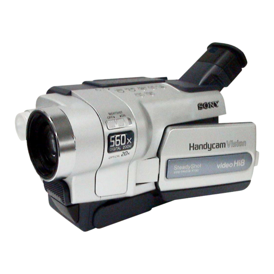
 CABINET (R) BLOCK ASSEMBLY Control switch block (CF-3000) Tape (A) Harness When installing Control switch block (CF-3000), set harness and tape (A) as shown in the figure.
CCD-TRV118/TRV218E/TRV318/TRV418/TRV418E COVER COVER 3. BLOCK DIAGRAMS Link Link OVERALL BLOCK DIAGRAM (1/5) OVERALL BLOCK DIAGRAM (1/5) OVERALL BLOCK DIAGRAM (5/5) OVERALL BLOCK DIAGRAM (5/5) OVERALL BLOCK DIAGRAM (2/5) POWER BLOCK DIAGRAM (1/2) OVERALL BLOCK DIAGRAM (2/5) POWER BLOCK DIAGRAM (1/2)
Page 37
CCD-TRV118/TRV218E/TRV318/TRV418/TRV418E SECTION 3 3. BLOCK DIAGRAMS 3. BLOCK DIAGRAMS COVER COVER BLOCK DIAGRAMS 3-1. OVERALL BLOCK DIAGRAM (1/5) ( ) : Number in parenthesis ( ) indicates the division number of schematic diagram where the component is located. CD-409 BOARD...
Page 38
CCD-TRV118/TRV218E/TRV318/TRV418/TRV418E 3. BLOCK DIAGRAMS 3. BLOCK DIAGRAMS COVER COVER ( ) : Number in parenthesis ( ) indicates the division number of schematic diagram where the component is located. 3-2. OVERALL BLOCK DIAGRAM (2/5) VC-303 BOARD (2/4) VIDEO HEAD PB C RF...
Page 39
CCD-TRV118/TRV218E/TRV318/TRV418/TRV418E 3. BLOCK DIAGRAMS 3. BLOCK DIAGRAMS COVER COVER 3-3. OVERALL BLOCK DIAGRAM (3/5) ( ) : Number in parenthesis ( ) indicates the division number of schematic diagram where the component is located. VC-303 BOARD (3/4) M2100/M2101 MECHA DECK (2/2)
Page 40
CCD-TRV118/TRV218E/TRV318/TRV418/TRV418E 3. BLOCK DIAGRAMS 3. BLOCK DIAGRAMS COVER COVER ( ) : Number in parenthesis ( ) indicates the division number of schematic diagram where the component is located. 3-4. OVERALL BLOCK DIAGRAM (4/5) VC-303 BOARD (4/4) CONTROL SWITCH PD-180 BOARD (1/2)
Page 41
CCD-TRV118/TRV218E/TRV318/TRV418/TRV418E 3. BLOCK DIAGRAMS 3. BLOCK DIAGRAMS COVER COVER 3-5. OVERALL BLOCK DIAGRAM (5/5) ( ) : Number in parenthesis ( ) indicates the division number of schematic diagram where the component is located. TYPE C/S: Please refer to page 1-2 to discriminate the type of LCD.
Page 42
CCD-TRV118/TRV218E/TRV318/TRV418/TRV418E 3. BLOCK DIAGRAMS 3. BLOCK DIAGRAMS COVER COVER ( ) : Number in parenthesis ( ) indicates the division number of schematic diagram where the component is located. 3-6. POWER BLOCK DIAGRAM (1/2) VC-303 BOARD (1/2) BT901 BATTERY BATT SIG...
Page 43
CCD-TRV118/TRV218E/TRV318/TRV418/TRV418E 3. BLOCK DIAGRAMS 3. BLOCK DIAGRAMS COVER COVER 3-7. POWER BLOCK DIAGRAM (2/2) ( ) : Number in parenthesis ( ) indicates the division number of schematic diagram where the component is located. VC-303 BOARD (2/2) CONTROL SWITCH BLOCK (SS-3000)
CCD-TRV118/TRV218E/TRV318/TRV418/TRV418E 4-2. SCHEMATIC DIAGRAMS 4-2. SCHEMATIC DIAGRAMS COVER COVER 4-2. SCHEMATIC DIAGRAMS THIS NOTE IS COMMON FOR SCHEMATIC DIAGRAMS (In addition to this, the necessary note is printed in each block) (For schematic diagrams) 1. Connection • All capacitors are in µF unless otherwise noted. pF : µ...
Page 48
CCD-TRV118/TRV218E/TRV318/TRV418/TRV418E 4-2. SCHEMATIC DIAGRAMS 4-2. SCHEMATIC DIAGRAMS CD-409 BOARD CD-409 BOARD COVER COVER For Schematic Diagram • Refer to page 4-45 for printed wiring board. • Refer to page 4-61 for waveforms. CD-409 BOARD CCD IMAGER XX MARK:NO MOUNT NO MARK:REC/PB MODE...
Page 49
CCD-TRV118/TRV218E/TRV318/TRV418/TRV418E 4-2. SCHEMATIC DIAGRAMS 4-2. SCHEMATIC DIAGRAMS VC-303 BOARD SIDE A VC-303 BOARD SIDE A VC-303 BOARD SIDE B VC-303 BOARD SIDE B COVER COVER For Schematic Diagram • Refer to page 4-47 for printed wiring board. • Refer to page 4-62 for waveforms.
Page 50
CCD-TRV118/TRV218E/TRV318/TRV418/TRV418E 4-2. SCHEMATIC DIAGRAMS 4-2. SCHEMATIC DIAGRAMS VC-303 BOARD SIDE A VC-303 BOARD SIDE A VC-303 BOARD SIDE B VC-303 BOARD SIDE B COVER COVER For Schematic Diagram • Refer to page 4-47 for printed wiring board. • Refer to page 4-62, 4-63 for waveforms.
Page 51
CCD-TRV118/TRV218E/TRV318/TRV418/TRV418E 4-2. SCHEMATIC DIAGRAMS 4-2. SCHEMATIC DIAGRAMS VC-303 BOARD SIDE A VC-303 BOARD SIDE A VC-303 BOARD SIDE B VC-303 BOARD SIDE B COVER COVER For Schematic Diagram • Refer to page 4-47 for printed wiring board. VC-303 BOARD (3/11)
Page 52
CCD-TRV118/TRV218E/TRV318/TRV418/TRV418E 4-2. SCHEMATIC DIAGRAMS 4-2. SCHEMATIC DIAGRAMS VC-303 BOARD SIDE A VC-303 BOARD SIDE A VC-303 BOARD SIDE B VC-303 BOARD SIDE B COVER COVER For Schematic Diagram • Refer to page 4-47 for printed wiring board. • Refer to page 4-63 for waveforms.
Page 53
CCD-TRV118/TRV218E/TRV318/TRV418/TRV418E 4-2. SCHEMATIC DIAGRAMS 4-2. SCHEMATIC DIAGRAMS VC-303 BOARD SIDE A VC-303 BOARD SIDE A VC-303 BOARD SIDE B VC-303 BOARD SIDE B COVER COVER For Schematic Diagram • Refer to page 4-47 for printed wiring board. • Refer to page 4-64 for waveforms.
Page 54
CCD-TRV118/TRV218E/TRV318/TRV418/TRV418E 4-2. SCHEMATIC DIAGRAMS 4-2. SCHEMATIC DIAGRAMS VC-303 BOARD SIDE A VC-303 BOARD SIDE A VC-303 BOARD SIDE B VC-303 BOARD SIDE B COVER COVER For Schematic Diagram • Refer to page 4-47 for printed wiring board. • Refer to page 4-64 for waveforms.
Page 55
CCD-TRV118/TRV218E/TRV318/TRV418/TRV418E 4-2. SCHEMATIC DIAGRAMS 4-2. SCHEMATIC DIAGRAMS VC-303 BOARD SIDE A VC-303 BOARD SIDE A VC-303 BOARD SIDE B VC-303 BOARD SIDE B COVER COVER For Schematic Diagram • Refer to page 4-47 for printed wiring board. • Refer to page 4-64 for waveforms.
Page 56
CCD-TRV118/TRV218E/TRV318/TRV418/TRV418E 4-2. SCHEMATIC DIAGRAMS 4-2. SCHEMATIC DIAGRAMS VC-303 BOARD SIDE A VC-303 BOARD SIDE A VC-303 BOARD SIDE B VC-303 BOARD SIDE B COVER COVER For Schematic Diagram • Refer to page 4-47 for printed wiring board. • Refer to page 4-65 for waveforms.
Page 57
CCD-TRV118/TRV218E/TRV318/TRV418/TRV418E 4-2. SCHEMATIC DIAGRAMS 4-2. SCHEMATIC DIAGRAMS VC-303 BOARD SIDE A VC-303 BOARD SIDE A VC-303 BOARD SIDE B VC-303 BOARD SIDE B COVER COVER For Schematic Diagram • Refer to page 4-47 for printed wiring board. • Refer to page 4-65 for waveforms.
Page 58
CCD-TRV118/TRV218E/TRV318/TRV418/TRV418E 4-2. SCHEMATIC DIAGRAMS 4-2. SCHEMATIC DIAGRAMS VC-303 BOARD SIDE A VC-303 BOARD SIDE A VC-303 BOARD SIDE B VC-303 BOARD SIDE B COVER COVER For Schematic Diagram • Refer to page 4-47 for printed wiring board. • Refer to page 4-65 for waveforms.
Page 59
CCD-TRV118/TRV218E/TRV318/TRV418/TRV418E 4-2. SCHEMATIC DIAGRAMS 4-2. SCHEMATIC DIAGRAMS VC-303 BOARD SIDE A VC-303 BOARD SIDE A VC-303 BOARD SIDE B VC-303 BOARD SIDE B COVER COVER For Schematic Diagram • Refer to page 4-47 for printed wiring board. VC-303 BOARD (11/11)
Page 60
CCD-TRV118/TRV218E/TRV318/TRV418/TRV418E 4-2. SCHEMATIC DIAGRAMS 4-2. SCHEMATIC DIAGRAMS PD-180 BOARD SIDE A PD-180 BOARD SIDE A PD-180 BOARD SIDE B PD-180 BOARD SIDE B COVER COVER For Schematic Diagram • Refer to page 4-51 for printed wiring board. • Refer to page 4-66, 4-67 for waveforms.
Page 61
CCD-TRV118/TRV218E/TRV318/TRV418/TRV418E 4-2. SCHEMATIC DIAGRAMS 4-2. SCHEMATIC DIAGRAMS PD-180 BOARD SIDE A PD-180 BOARD SIDE A PD-180 BOARD SIDE B PD-180 BOARD SIDE B COVER COVER For Schematic Diagram • Refer to page 4-51 for printed wiring board. PD-180 BOARD (2/2)
Page 62
CCD-TRV118/TRV218E/TRV318/TRV418/TRV418E 4-2. SCHEMATIC DIAGRAMS 4-2. SCHEMATIC DIAGRAMS SI-035 BOARD SI-035 BOARD FP-569 FLEXIBLE BOARD FP-569 FLEXIBLE BOARD COVER COVER For Schematic Diagram • Refer to page 4-55, 4-57 for printed wiring board. TRV218E/TRV418/TRV418E SI-035 BOARD XX MARK:NO MOUNT IC751 NO MARK:REC/PB MODE...
Page 64
CCD-TRV118/TRV218E/TRV318/TRV418/TRV418E 4-2. SCHEMATIC DIAGRAMS 4-2. SCHEMATIC DIAGRAMS COVER COVER CONTROL SWITCH BLOCK (CF-3000) XX MARK:NO MOUNT VOLUME CONTROL SWITCH BLOCK (CF-3000) is replaced as block, so that PRINTED WIRING BOARD is omited. SP901 SPEAKER S008 END SEARCH R005 1200 R012...
CCD-TRV118/TRV218E/TRV318/TRV418/TRV418E 4-2. SCHEMATIC DIAGRAMS 4-2. SCHEMATIC DIAGRAMS COVER COVER CONTROL SWITCH BLOCK(SS-3000) CONTROL SWITCH BLOCK (PR-3000) XX MARK:NO MOUNT CONTROL SWITCH BLOCK (SS-3000) is replaced as block, so that PRINTED WIRING BOARD is omited. VC-303 (11/11) CONTROL SWITCH BLOCK (PR-3000) is replaced as block, so that PRINTED WIRING BOARD is omited.
Page 76
CCD-TRV118/TRV218E/TRV318/TRV418/TRV418E VC-303 BOARD SIDE A VC-303 BOARD SIDE B VC-303 BOARD SIDE A VC-303 BOARD SIDE B COVER COVER VC-303 BOARD (1/4) 1.5 Vp-p 260 mVp-p NTSC: 28.636 MHz PAL: 28.375 MHz IC271 5 (X271) REC/PB IC272 eh PB 430 mVp-p 1.6 Vp-p...
Page 77
CCD-TRV118/TRV218E/TRV318/TRV418/TRV418E VC-303 BOARD SIDE A VC-303 BOARD SIDE B VC-303 BOARD SIDE A VC-303 BOARD SIDE B COVER COVER VC-303 BOARD (2/4) 470 mVp-p 1.9 Vp-p NTSC: 14.318 MHz PAL: 14.187 MHz IC151 qj REC/PB IC151 yh PB 3.8 Vp-p...
Page 78
CCD-TRV118/TRV218E/TRV318/TRV418/TRV418E VC-303 BOARD SIDE A VC-303 BOARD SIDE B VC-303 BOARD SIDE A VC-303 BOARD SIDE B COVER COVER VC-303 BOARD (3/4) 2.8 Vp-p 1.3 Vp-p NTSC: 180 Hz NTSC: 820 Hz PAL: 150 Hz PAL: 1148 Hz IC451 tj, tl, ya REC/PB IC452 wf REC/PB 1.3 Vp-p...
Page 79
CCD-TRV118/TRV218E/TRV318/TRV418/TRV418E VC-303 BOARD SIDE A VC-303 BOARD SIDE B VC-303 BOARD SIDE A VC-303 BOARD SIDE B COVER COVER VC-303 BOARD (4/4) 820 mVp-p 340 mVp-p CN705 8 REC/PB IC651 5 REC/PB 8.4 Vp-p 2.8 Vp-p NTSC: 500 kHz PAL: 485 kHz...
Page 80
CCD-TRV118/TRV218E/TRV318/TRV418/TRV418E PD-180 BOARD SIDE A PD-180 BOARD SIDE B PD-180 BOARD SIDE A PD-180 BOARD SIDE B COVER COVER PD-180 BOARD (1/2) 3.5 Vp-p (TYPE C) 460 mVp-p 4.0 Vp-p (TYPE S) IC5501 rk REC/PB IC5501 wf REC/PB 5.5 Vp-p...
Page 81
CCD-TRV118/TRV218E/TRV318/TRV418/TRV418E PD-180 BOARD SIDE A PD-180 BOARD SIDE B PD-180 BOARD SIDE A PD-180 BOARD SIDE B COVER COVER PD-180 BOARD (2/2) 2.8 Vp-p IC5502 rk REC/PB PD-180 (2/2) 4-67...
CCD-TRV118/TRV218E/TRV318/TRV418/TRV418E 4-3. PRINTED WIRING BOARDS 4-3. PRINTED WIRING BOARDS COVER COVER 4-5. MOUNTED PARTS LOCATION no mark : side A * mark : side B VC-303 BOARD * C003 C162 * C385 C663 R023 * C004 C163 * C386 C702...
Page 83
CCD-TRV118/TRV218E/TRV318/TRV418/TRV418E 4-3. PRINTED WIRING BOARDS 4-3. PRINTED WIRING BOARDS COVER COVER no mark : side A * mark : side B PD-180 BOARD SI-035 BOARD * R252 R567 C5503 R5534 C-4 C751 * R274 R572 C5504 R5542 B-2 * C752...
CCD-TRV118/TRV218E/TRV318/TRV418/TRV418E COVER COVER NOTE NOTE 5. REPAIR PARTS LIST NOTE: Characters A to L of the electrical parts list indicate location of exploded views in which the desired part is shown. EXPLODED VIEWS EXPLODED VIEWS Link Link OVERALL ASSEMBLY F PANEL BLOCK ASSEMBLY...
Page 85
CCD-TRV118/TRV218E/TRV318/TRV418/TRV418E 5. REPAIR PARTS LIST 5. REPAIR PARTS LIST COVER COVER NOTE: • -XX, -X mean standardized parts, so they may have some differences from When indicating parts by reference number, the original one. please include the board name. •...
CCD-TRV118/TRV218E/TRV318/TRV418/TRV418E 5. REPAIR PARTS LIST 5. REPAIR PARTS LIST COVER COVER 5-1. EXPLODED VIEWS 5-1-1. OVERALL ASSEMBLY Battery panel block assembly (See page 5-8.) MD frame block (See page 5-9.) EVF block assembly (See page 5-7.) Cabinet (R) block assembly (See page 5-6.)
Page 87
CCD-TRV118/TRV218E/TRV318/TRV418/TRV418E 5. REPAIR PARTS LIST 5. REPAIR PARTS LIST COVER COVER 5-1-2. F PANEL BLOCK ASSEMBLY ns: not supplied SE752 SE751 S I - D752 D753 IC751 MIC901 Ref. No. Part No. Description Ref. No. Part No. Description X-3952-950-1 PANEL (30) ASSY, FRONT...
Page 88
CCD-TRV118/TRV218E/TRV318/TRV418/TRV418E 5. REPAIR PARTS LIST 5. REPAIR PARTS LIST COVER COVER 5-1-3. LENS BLOCK ASSEMBLY - 4 0 IC951 (Note 1) (Note 1) Be sure to read “Precuations for Replacement of CCD Imager” on page 4-8 when changing the CCD imager.
Page 89
CCD-TRV118/TRV218E/TRV318/TRV418/TRV418E 5. REPAIR PARTS LIST 5. REPAIR PARTS LIST COVER COVER 5-1-4. LCD BLOCK ASSEMBLY LCD901 (Note 2) ND901 - 1 8 (Note 2) (Note 2) About PD-180 board and LCD module, discriminate LCD type on the machine referring to page 1-2, and replace the same type.
Page 90
CCD-TRV118/TRV218E/TRV318/TRV418/TRV418E 5. REPAIR PARTS LIST 5. REPAIR PARTS LIST COVER COVER 5-1-5. CABINET (R) BLOCK ASSEMBLY ns: not supplied : BT001 (BATTERY, LITHIUM SECONDARY) Included in the control switch block (CF-3000). Ref. No. Part No. Description Ref. No. Part No.
Page 91
CCD-TRV118/TRV218E/TRV318/TRV418/TRV418E 5. REPAIR PARTS LIST 5. REPAIR PARTS LIST COVER COVER 5-1-6. EVF BLOCK ASSEMBLY ns: not supplied LCD902 Ref. No. Part No. Description Ref. No. Part No. Description X-3952-968-1 HINGE (30) ASSY, VF X-3951-166-1 LENS (M) ASSY, VF X-3952-956-1 CABINET (LOWER) (30) (M) ASSY, EVF 3-065-567-01 TAPPING (M1.7)
Page 92
CCD-TRV118/TRV218E/TRV318/TRV418/TRV418E 5. REPAIR PARTS LIST 5. REPAIR PARTS LIST COVER COVER 5-1-7. BATTERY PANEL BLOCK ASSEMBLY ns: not supplied BT901 Ref. No. Part No. Description Ref. No. Part No. Description 3-079-039-01 SHEET METAL (LOWER) (30),STRAP 3-067-347-01 MI SCREW M2 (H)
Page 93
CCD-TRV118/TRV218E/TRV318/TRV418/TRV418E 5. REPAIR PARTS LIST 5. REPAIR PARTS LIST COVER COVER 5-1-8. MD FRAME BLOCK ns: not supplied Mechanism deck (See page 5-10 to 5-13.) - 3 0 Ref. No. Part No. Description Ref. No. Part No. Description 1-686-856-11 FP-573 FLEXIBLE BOARD...
Page 94
CCD-TRV118/TRV218E/TRV318/TRV418/TRV418E 5. REPAIR PARTS LIST 5. REPAIR PARTS LIST COVER COVER 5-1-9. CASSETTE COMPARTMENT ASSEMBLY, DRUM ASSEMBLY ns: not supplied LS chassis block assembly M901 (See page 5-11.) Mechanical chassis block assembly (See page 5-12 to 5-13.) Ref. No. Part No.
Page 95
CCD-TRV118/TRV218E/TRV318/TRV418/TRV418E 5. REPAIR PARTS LIST 5. REPAIR PARTS LIST COVER COVER 5-1-10. LS CHASSIS BLOCK ASSEMBLY S001 ns: not supplied S002 Q001 H001 D001 LS-057 H002 Q002 FP-301 FP-302 FP-300 Ref. No. Part No. Description Ref. No. Part No. Description...
Page 96
CCD-TRV118/TRV218E/TRV318/TRV418/TRV418E 5. REPAIR PARTS LIST 5. REPAIR PARTS LIST COVER COVER 5-1-11. MECHANICAL CHASSIS BLOCK ASSEMBLY-1 ns: not supplied M902 M903 Mechanical chassis block assembly-2 (See page 5-13.) Ref. No. Part No. Description Ref. No. Part No. Description A-7096-422-A BASE ASSY, DRUM 3-065-881-01 SPRING, P PRESSURE PLATE 3-947-503-01 SCREW (M1.4)
Page 97
CCD-TRV118/TRV218E/TRV318/TRV418/TRV418E 5. REPAIR PARTS LIST 5. REPAIR PARTS LIST COVER COVER 5-1-12. MECHANICAL CHASSIS BLOCK ASSEMBLY-2 Ref. No. Part No. Description Ref. No. Part No. Description 3-065-920-01 ARM, HC DRIVE 7-624-101-04 STOP RING 1.2 (E TYPE) 3-065-913-01 GEAR (4), LD...
Owner’s Record The model and serial numbers are located on the bottom. Record the serial number in the space provided below. Refer to these numbers whenever you call upon your Sony dealer regarding this product. Model No. -TRV Model No. AC- Serial No.
Welcome! Congratulations on your purchase of this Sony Handycam. With your Handycam, you can capture life’s precious moments with superior picture and sound quality. Your Handycam is loaded with advanced features, but at the same time it is very easy to use. You will soon be producing home video that you can enjoy for years to come.
Page 112
Note: For the customers in the This equipment has been tested and found to U.S.A. and CANADA comply with the limits for a Class B digital device, pursuant to Part 15 of the FCC Rules. CAUTION These limits are designed to provide TO PREVENT ELECTRIC SHOCK, MATCH reasonable protection against harmful WIDE BLADE OF PLUG TO WIDE SLOT,...
Main Features On the model name indication In this manual, camcorder-shape icons are used to indicate model names. CCD-TRV118 : DCR-TRV150 : CCD-TRV318 : DCR-TRV250 : CCD-TRV418 : DCR-TRV350 : DCR-TRV351 : Instructions with no icons are for all models.
Page 114
Main Features Other uses Functions for adjusting exposure in the recording mode •BACK LIGHT (p. 38) •NightShot (p. 39) •Super NightShot/Color Slow Shutter (p. 39, 40) •PROGRAM AE (p. 68) •Adjusting the exposure manually (p. 70) •Built-in light (p. 79) Functions for giving images more impact •Digital zoom (p.
Page 115
Table of contents Main Features .......... 4 Advanced Recording Checking supplied accessories ....9 Operations Recording still images on a “Memory Quick Start Guide Stick” while recording on a tape – Recording on a tape ......10 ........53 – Recording on a “Memory Stick” Recording still images on a tape ........
Page 116
Table of contents Editing – Playback Dubbing a tape ........94 Viewing still images – Memory Photo playback ..163 Dubbing a tape easily – Easy Dubbing ......98 Viewing moving pictures – MPEG movie playback ..... 166 Dubbing only desired scenes –...
Page 117
Table of contents • , are trademarks. Customizing Your Camcorder • i.LINK and are trademarks. • “InfoLITHIUM” is a trademark of Sony Changing the menu settings ....210 Corporation. • “Memory Stick,” and “MagicGate Troubleshooting Memory Stick” are trademarks of Sony Corporation.
Quick Start Guide – Recording on a tape This chapter introduces you to the basic features to record on a tape of your camcorder. See the page in parentheses “( )” for more information. Connecting the power cord (p. 24) Use the battery pack when using your camcorder outdoors (p.
Page 120
Recording a picture (p. 30) Set the POWER switch Remove the lens cap. to CAMERA while The cap is not attached when you pressing the small purchase your camcorder. green button. Open the LCD panel while pressing OPEN. The picture appears on the LCD screen.
Page 121
Quick Start Guide – Recording on a “Memory Stick” This chapter introduces you to the basic features to record on a “Memory Stick” of your camcorder. See the page in parentheses “( )” for more information. Connecting the power cord (p.
Page 122
Recording a still image on a “Memory Stick” (p. 132) Set the POWER switch to Remove the lens cap. MEMORY while pressing the The cap is not attached when you small green button. Make sure purchase your camcorder. that the LOCK switch is set to the left (unlock) position.
— Getting Started — Using this manual The instructions in this manual are for the seven models listed in the table below. Before you start reading this manual and operating your camcorder, check the model number by looking at the bottom of your camcorder. The DCR-TRV350 is the model used for illustration purposes.
Page 124
Using this manual Before using your camcorder With your camcorder, you can use the tapes and record/playback on the systems below. To enable smooth transition, we recommend that you do not mix pictures recorded in the Hi8 /standard 8 mm with the Digital8 system on a tape.
Page 125
Unauthorized recording of such materials may be contrary to the provision of the copyright laws. On the model name indication In this manual, camcorder-shape icons are used to indicate model names. CCD-TRV118 : DCR-TRV150 : CCD-TRV318 : DCR-TRV250 : CCD-TRV418 :...
Using this manual Precautions on camcorder care Lens and LCD screen/finder • The LCD screen and the finder are manufactured using extremely high-precision technology so over 99.99% of the pixels are operational for effective use. However, there may be some tiny black points and/or bright points (white, red, blue or green in color) that constantly appear on the LCD screen and the finder.
Step 1 Preparing the power supply Installing the battery pack (1) Lift up the viewfinder. (2) Slide the battery pack down until it clicks. To remove the battery pack (1) Lift up the viewfinder. (2) Slide the battery pack out in the direction of the arrow while pressing the BATT (battery) release lever down.
Step 1 Preparing the power supply Charging the battery pack Use the battery pack after charging it for your camcorder. Your camcorder operates only with the “InfoLITHIUM” battery pack (M series). See page 242 for details of “InfoLITHIUM” battery pack. (1) Open the DC IN jack cover and connect the AC Adaptor supplied with your camcorder to the DC IN jack with the plug’s v mark facing up.
Page 129
Step 1 Preparing the power supply To check the state of the battery (BATTERY INFO) Open the LCD panel while pressing OPEN, then press BATT INFO. The BATTERY INFO is displayed for about seven seconds. The battery charge level is displayed as percentage and recordable BATTERY INFO time with the LCD screen/viewfinder.
Step 1 Preparing the power supply If the power goes off although the remaining battery time indicator indicates that the battery pack has enough power to operate Charge the battery pack fully again so that the indication is correct. What is “InfoLITHIUM”? The “InfoLITHIUM”...
Step 1 Preparing the power supply Recording time Recording with Recording with Battery pack the viewfinder the LCD screen Continuous Typical* Continuous Typical* NP-FM30 (supplied) NP-FM50 NP-FM70 NP-QM71/QM71D NP-FM90 NP-FM91/QM91/QM91D Recording with Recording with Battery pack the viewfinder the LCD screen Continuous Typical* Continuous...
Step 1 Preparing the power supply Playing time Playing on Playing with Battery pack the LCD screen the LCD closed NP-FM30 (supplied) NP-FM50 NP-FM70 NP-QM71/QM71D NP-FM90 NP-FM91/QM91/QM91D Playing on Playing with Battery pack the LCD screen the LCD closed NP-FM30 (supplied) NP-FM50 NP-FM70 NP-QM71/QM71D...
Step 1 Preparing the power supply Note Approximate continuous playing time at 25°C (77°F). The battery life will be shorter if you use your camcorder in a cold environment. Playback time The table shows the playing time for tapes recorded in the Digital8 system.
Page 134
While using the AC Adaptor, if any trouble occurs with this unit, disconnect the plug from the wall outlet as soon as possible to cut off the power. Using a car battery Use Sony Car Battery Adaptor (optional). Refer to the operating instructions of the Car Battery Adaptor for further information.
Step 2 Setting the date and time Set the date and time when you use your camcorder for the first time. “CLOCK SET” will be displayed each time when you set the POWER switch to CAMERA or MEMORY unless you set the date and time settings.* If you do not use your camcorder for about three months, the date and time settings may be cleared from memory (bars may appear) because the built-in rechargeable battery will have been discharged (p.
Step 2 Setting the date and time The year changes as follows: 2000 2003 2079 To check the preset date and time Press DATE to display the date indicator. Press TIME to display the time indicator. Press DATE (or TIME) and then press TIME (or DATE) to simultaneously display the date and time indicator.
Step 3 Inserting a cassette See page 15 for details about the usable cassettes types. (1) Prepare the power source (p. 18). (2) Slide OPEN/EJECT in the direction of the arrow and open the lid. The cassette compartment automatically lifts up and opens. (3) Push the center of the cassette back and insert the cassette properly with the cassette window facing up.
Page 138
Step 3 Inserting a cassette Notes •Do not press the cassette compartment down. Doing so may cause a malfunction. •The cassette compartment may not be closed when you press any part of the cassette compartment other than the mark. •Your camcorder records pictures in the Digital8 system.
— Recording – Basics — Recording a picture Your camcorder automatically focuses. (1) Remove the lens cap and attach the lens cap to the grip strap. (2) Install the power source and insert a cassette. See “Step 1” to “Step 3” for more information (p.
Page 140
Recording a picture Note on the LOCK switch When you slide the LOCK switch to the right, the POWER switch can no longer be set to MEMORY accidentally. The LOCK switch is set to the left as the default setting. Note on recording mode Your camcorder records and plays back in the SP (standard play) mode or in the LP (long play) mode.
Recording a picture After recording (1) Set the POWER switch to OFF (CHG). (2) Close the LCD panel. (3) Eject the cassette. (4) Attach the lens cap. (5) Remove the battery pack. After using your camcorder Remove the battery pack from your camcorder to avoid turning on the built-in light accidentally.
Recording a picture Adjusting the brightness of the LCD screen (1) Set the POWER switch to CAMERA, VCR/PLAYER or MEMORY.* (2) Turn the SEL/PUSH EXEC dial to select LCD BRIGHT in in the menu settings, then press the dial (p. 216). (3) Turn the SEL/PUSH EXEC dial to adjust the brightness of the LCD screen with LCD BRIGHT, then press the dial.
Recording a picture Using the zoom feature Set the POWER switch to CAMERA or MEMORY.* Move the power zoom lever a little for a slower zoom. Move it further for a faster zoom. Using the zoom function sparingly results in better-looking recordings. “T”...
Recording a picture Adjusting the viewfinder lens If you record pictures with the LCD panel closed, check the picture with the viewfinder. Adjust the viewfinder lens to your eyesight so that the indicators in the viewfinder come into sharp focus. Set the POWER switch to CAMERA, VCR/PLAYER or MEMORY.* Lift up the viewfinder and move the viewfinder lens adjustment lever.
Page 145
Recording a picture Pictures in the mirror mode The picture on the LCD screen is a mirror-image. However, the picture will be normal when recorded. During recording in the mirror mode DATE and TIME on your camcorder do not work. Indicators displayed in the recording mode The indicators are not recorded on the tape.
Page 146
Recording a picture Remaining battery time indicator The remaining battery time indicator indicates the approximate recording time. The indicator may not be correct, depending on the conditions in which you are recording. When you close the LCD panel and open it again, it takes about one minute for the correct remaining battery time in minutes to be displayed.
Recording a picture Shooting a backlit subject – BACK LIGHT When you shoot a subject with the light source behind the subject or a subject with a light background, use the backlight function. Set the POWER switch to CAMERA or MEMORY, and press BACK LIGHT.* The .
Recording a picture Shooting in the dark – NightShot – Super NightShot – Color Slow Shutter The NightShot function enables you to shoot a subject in a dark place. For example, you can satisfactorily record the environment of nocturnal animals for observation when you use this function.
Recording a picture Using Color Slow Shutter The Color Slow Shutter function enables you to record color images in a dark place. (1) Set the POWER switch to CAMERA, and slide NIGHTSHOT to OFF. (2) Press COLOR SLOW S. indicator and COLOR SLOW SHUTTER flash on the screen. To cancel the Color Slow Shutter function, press COLOR SLOW S again.
Recording a picture Self-timer recording Recording with the self-timer starts in 10 seconds automatically. You can also use the Remote Commander for this operation. (1) In the standby mode, press MENU to display the menu settings. (2) Turn the SEL/PUSH EXEC dial to select SELFTIMER in , then press the dial.
Recording a picture Superimposing the date and time on pictures You can record the date and/or time displayed on the screen superimposed on the picture. Carry out the following operations in CAMERA mode. Press DATE to record the date. Press TIME to record the time. Press DATE (or TIME), then press TIME (or DATE) to record the date and time.
Checking recordings – END SEARCH – EDITSEARCH – Rec Review You can use these buttons to check the recorded picture for making the transition between the last recorded scene and the next scene you record smooth. END SEARCH EDITSEARCH END SEARCH You can go to the end of the recorded section after you record.
Checking recordings – END SEARCH – EDITSEARCH – Rec Review Notes •The end search, edit search and Rec Review functions do not work with tapes recorded in the Hi8 /standard 8 mm system. •If you start recording after using the end search function, occasionally, the transition between the last scene you recorded and the next scene may not be smooth.
— Playback – Basics — Playing back a tape You can monitor the playback picture on the LCD screen. If you close the LCD panel, you can monitor the playback picture in the viewfinder. You can control playback using the Remote Commander supplied with your camcorder.
Page 155
Playing back a tape If you leave the power on for a long time Your camcorder gets warm. This is not a malfunction. Tapes that can be played back •Tapes recorded in the Digital8 system •Tapes recorded in the Hi8 /standard 8 mm system When monitoring on the LCD screen...
Playing back a tape To display the screen indicators – Display function Press DISPLAY on the Remote Commander. Press DISPLAY on your camcorder. The indicators appear on the screen. To make the indicators disappear, press DISPLAY again. DATA CODE DISPLAY DISPLAY About data code Use the Remote Commander for this operation.
Page 157
Playing back a tape To not display various settings Set DATA CODE to DATE in the menu settings (p. 222). The display changes as follows when you press DATA CODE on the Remote Commander: date/time y no indicator Notes on the data code •The data code does not work with tapes recorded in the Hi8 /standard 8 mm system.
Playing back a tape Various playback modes To operate the video control buttons, set the POWER switch to VCR/PLAYER.* To pause playback (viewing a still image) Press X during playback. To resume normal playback, press X or N. To advance the tape Press M in the stop mode.
Page 159
Playing back a tape In the various playback modes •The previous recording may appear as a mosaic image when playing back in the Digital8 system. •Noise may appear when your camcorder plays back tapes recorded in the Hi8 standard 8 mm system.
Viewing recordings on TV Connect your camcorder to your TV with the A/V connecting cable supplied with your camcorder to watch playback pictures on the TV screen. You can operate the video control buttons in the same way as when you monitor playback pictures on the LCD screen.
Viewing recordings on TV If your TV is already connected to a VCR Connect your camcorder to the LINE IN input on the VCR by using the A/V connecting cable supplied with your camcorder. Set the input selector on the VCR to LINE. If your TV or VCR is a monaural type Connect the yellow plug of the A/V connecting cable to the video input jack and the white or the red plug to the audio input jack on the VCR or the TV.
— Advanced Recording Operations — Recording still images on a “Memory Stick” while recording on a tape You can record still images on a “Memory Stick” in the tape recording or standby mode. Before operation Insert a “Memory Stick” into your camcorder (p. 127). In the standby mode or during tape recording, press PHOTO deeper.
Page 163
Recording still images on a “Memory Stick” while recording on a tape “Memory Stick” For more information, see page 240. Notes •Do not shake or strike your camcorder when you record still images. The image may fluctuate. •You cannot record still images on a “Memory Stick” in the following functions: –...
Page 164
Recording still images on a “Memory Stick” while recording on a tape Self-timer recording You can record still images on a “Memory Stick” with the self-timer. You can also use the Remote Commander for this operation. Before operation Insert a “Memory Stick” into your camcorder (p. 127). (1) In the standby mode, press MENU to display the menu settings.
Recording still images on a tape – Tape Photo recording You can record a still image like a photograph. You can record about 510 images in the SP mode and about 765 images in the LP mode on a tape which can record for 60 minutes in the SP mode. In the standby mode or during tape recording, press PHOTO deeper.
Page 166
Recording still images on a tape – Tape Photo recording Notes •During Tape Photo recording, you cannot change the mode or setting. •You cannot use PHOTO while using BOUNCE in the Fader function. •When recording a still image, do not shake your camcorder. The image may fluctuate. If you record a moving subject with the tape photo recording function The image may fluctuate when you play back the still image on other equipment.
Using the wide mode If you connect a TV compatible with the ID-1/ID-2 system, the screen size is automatically selected. You can record a 16:9 wide picture to watch on the 16:9 wide-screen TV (16:9WIDE). 16:9WIDE 16:9WIDE [a]: Recording in the 16:9WIDE mode [b]: Playback on a normal TV [c]: Playback on a wide TV in the normal screen mode [d]: Full screen mode on a wide TV...
Page 168
Using the wide mode You can record a cinema-like picture (CINEMA) or a 16:9 wide picture (16:9FULL) to watch on the 16:9 wide-screen TV. Refer to the operating instructions of your TV. CINEMA CINEMA 16:9FULL 16:9FULL [a]: Recording in the CINEMA mode [b]: Playback on a normal TV [c]: Playback on a wide TV in the normal screen mode [d]: Zoom mode on a wide TV...
Using the wide mode To cancel the wide mode In the standby mode, set the wide mode to OFF in the menu settings. In the wide mode You cannot operate the following functions: – OLD MOVIE (p. 65) – Recording still images on a “Memory Stick” in tape recording or tape recording standby –...
Using the fader function You can fade in or out to give your recording a professional appearance. FADER M.FADER (mosaic) STRIPE BOUNCE * OVERLAP * WIPE * DOT * (random dot) MONOTONE When fading in, the picture gradually changes from black-and-white to color. When fading out, the picture gradually changes from color to black-and-white.
Page 171
Using the fader function (1) To fade in [a] In the standby mode, press FADER until the desired fader indicator flashes. To fade out [b] In the recording mode, press FADER until the desired fader indicator flashes. The indicator changes as follows: FADER t M.FADER t STRIPE t BOUNCE t MONOTONE no indicator WIPE...
Page 172
Using the fader function When you set the POWER switch to MEMORY You cannot use the fader function. When you select OVERLAP, WIPE, or DOT Your camcorder automatically stores the picture recorded on the tape. While the picture is being stored, the indicator flashes fast, and the picture from the tape appears on the screen.
Using special effects – Picture effect You can digitally process pictures to obtain special effects like those in films or on TV. NEG. ART [a] : The color and brightness of the picture are reversed. SEPIA : The picture appears in sepia. B&W : The picture appears in monochrome (black-and-white).
Using special effects – Digital effect You can add special effects to recorded images using the various digital functions. The sound is recorded normally. STILL You can record a still image so that it is superimposed on a moving picture. FLASH (FLASH MOTION) You can record still images successively at regular intervals.
Page 175
Using special effects – Digital effect (1) In CAMERA mode, press MENU to display the menu settings. (2) Turn the SEL/PUSH EXEC dial to select D EFFECT in , then press the dial (p. 211). (3) Turn the SEL/PUSH EXEC dial to select the desired digital effect mode. (4) Press the SEL/PUSH EXEC dial.
Page 176
Using special effects – Digital effect Notes •The following functions do not work during digital effects: – Fader – Super NightShot – Color Slow Shutter •The PROGRAM AE function does not work in the slow shutter mode. •The following functions do not work in the OLD MOVIE mode: –...
Using the PROGRAM AE function You can select the PROGRAM AE (Auto Exposure) mode to suit your specific shooting requirements. (SPOTLIGHT) This mode prevents people’s faces, for example, from appearing excessively white when shooting subjects lit by strong light in the theater. (PORTRAIT) This mode brings out the subject while creating a soft background for subjects such as people or flowers.
Page 178
Using the PROGRAM AE function (1) In CAMERA or MEMORY mode, press MENU to display the menu settings.* (2) Turn the SEL/PUSH EXEC dial to select PROGRAM AE in , then press the dial (p. 211). (3) Turn the SEL/PUSH EXEC dial to select the desired mode, then press the dial. MANUAL SET PROGRAM AE AUTO...
Adjusting the exposure manually You can manually adjust and set the exposure. Normally, exposure is automatically adjusted. Adjust the exposure manually in the following cases: – When the subject is backlit. – When shooting bright subjects against dark backgrounds. – When recording dark pictures (e.g. night scenes) faithfully. (1) In CAMERA or MEMORY mode, press EXPOSURE.* The exposure indicator appears on the screen.
Focusing manually You can gain better results by manually adjusting the focus in the following cases: •The autofocus mode is not effective when shooting: – Subjects through glass covered with water droplets. – Horizontal stripes. – Subjects with little contrast with backgrounds such as walls or the sky. •When you want to change the focus from a subject in the foreground to a subject in the background.
Interval recording Example You can make a time-lapse recording by setting your camcorder to automatically record and standby sequentially. You can achieve an excellent recording for flowering, 9 MIN 59 S 9 MIN 59 S gradual appearances, etc., with this function. 10 MIN 10 MIN [a]: Recording time (REC TIME)
Page 182
Interval recording TAPE SET TAPE SET REC MODE REC MODE AUTO MODE AUTO MODE REMAIN REMAIN FRAME REC FRAME REC I NT. REC I NT. REC RETURN RETURN [ MENU ] : END [ MENU ] : END TAPE SET REC MODE AUTO MODE REMAIN...
Frame by frame recording – Frame recording You can make a recording with a stop-motion animated effect using frame recording. To create this effect, alternately move the subject a little and make a frame recording. We recommend that you use a tripod, and operate your camcorder using the Remote Commander after step (5).
Superimposing a title You can select one of the eight preset titles and the two custom titles (p. 77). You can also select the language, color, size and position of titles. VACATION (1) In the standby mode, press TITLE to display the title menu. The title menu display appears on the screen.
Page 185
Superimposing a title To superimpose the title while you are recording Press TITLE while you are recording, and carry out steps (2) to (5). When you press the SEL/PUSH EXEC dial at step (5), the title is recorded. To select the language of a preset title If you want to change the language, select before step (2).
Making your own titles You can make up to two titles and store them in your camcorder. Each title can have up to 20 characters. (1) In CAMERA or VCR/PLAYER mode, press TITLE.* (2) Turn the SEL/PUSH EXEC dial to select , then press the dial.
Making your own titles To change a title you have stored In step (3), select CUSTOM1 SET or CUSTOM2 SET, depending on which title you want to change, then press the SEL/PUSH EXEC dial. Turn the SEL/PUSH EXEC dial to select [C], then press the dial to delete the title. The last character is erased.
Using the built-in light You can use the built-in light to suit your shooting situation. The recommended distance between the subject and camcorder is about 1.5 m (5 feet). In CAMERA or MEMORY mode, press LIGHT repeatedly until the indicator appears on the screen.* The indicator changes as follows: t no indicator...
Page 189
Using the built-in light Notes • The built-in light turns off automatically in the following cases: – When you leave it on for more than five minutes with the POWER switch set to MEMORY. – When it stays on in the AUTO mode ( ) for more than five minutes.
Be sure to align the tab with the groove when inserting. CAUTION •When replacing the bulb, use only the Sony XB-3D halogen lamp (optional) to reduce the risk of fire. •To prevent possible burn hazard, disconnect the power source before replacing and do not touch the bulb until the bulb becomes cool enough to handle (for about 30 minutes or more).
Inserting a scene You can insert a scene in the middle of a recorded tape by setting the start and end points. The previously recorded frames between these start and end points will be erased. Use the Remote Commander for this operation. (1) In the standby mode, keep pressing EDITSEARCH, and release the button at the insert end point [b].
— Advanced Playback Operations — Playing back a tape with picture effects During playback, you can process a scene using the following picture effects: NEG.ART, SEPIA, B&W and SOLARIZE. (1) In the playback or playback pause mode, press MENU to display the menu settings.
Page 193
Playing back a tape with picture effects Notes •You cannot record images on a tape on your camcorder while you are processing the image using Picture effect. However, you can record images as follows: – on a “Memory Stick” as a still image –...
Playing back a tape with digital effects During playback, you can process a scene using the following digital effects: STILL, FLASH, LUMI. and TRAIL. (1) In the playback mode or playback pause mode, press MENU to display the menu settings. (2) Turn the SEL/PUSH EXEC dial to select D EFFECT in , then press the dial (p.
Page 195
Playing back a tape with digital effects Notes •You cannot record images on a tape on your camcorder while you are processing the image using Digital effect. However, you can record images as follows: – on a “Memory Stick” as a still image –...
Enlarging recorded images – Tape PB ZOOM You can enlarge an image recorded on tapes. Besides the operation described here, your camcorder can enlarge still images recorded on a “Memory Stick” (p. 172). (1) In the playback or playback pause mode, press PB ZOOM. The center of the image is enlarged to about twice its size, and appear on the screen.
Page 197
Enlarging recorded images – Tape PB ZOOM Notes •You cannot record images on a tape or on a “Memory Stick” on your camcorder while you are processing the image using Tape PB ZOOM. However, you can record images on a VCR using your camcorder as a player. •Tape PB ZOOM does not work with tapes recorded in the Hi8 /standard 8 mm system.
Quickly locating a scene – ZERO SET MEMORY Your camcorder automatically searches for the scene having a tape counter value of “0:00:00. ” Use the Remote Commander for this operation. Use this function, for example, to view a desired scene later on during playback. (1) In the playback mode, press DISPLAY when the tape counter is not displayed on the screen.
Searching for a recording by date – DATE SEARCH Your camcorder can automatically search for the point where the recording date changes and starts playback from that point. Use the Remote Commander for this operation. Use this function to check where recording dates change or to edit the tape at each recording date.
Page 200
Searching for a recording by date – DATE SEARCH Notes •The date search function does not work with tapes recorded in the Hi8 standard 8 mm system. •If one day’s recording is less than two minutes, your camcorder may not accurately find the point where the recording date changes.
Searching for a photo – PHOTO SEARCH/PHOTO SCAN You can search for the still image recorded on a tape (photo search). You can also search for still images one after another and display each image for five seconds automatically (photo scan). Use the Remote Commander for these operations.
Searching for a photo – PHOTO SEARCH/PHOTO SCAN Scanning photo (1) Set the POWER switch to VCR. (2) Press SEARCH MODE on the Remote Commander repeatedly until the PHOTO SCAN indicator appears on the screen. The indicator changes as follows: DATE SEARCH t PHOTO SEARCH t PHOTO SCAN t (no indicator) (3) Press .
— Editing — Dubbing a tape Using the A/V connecting cable You can dub or edit on the VCR connected to your camcorder using your camcorder as a player. Before operation • Set DISPLAY to LCD in the menu settings. (The default setting is LCD.) •...
Page 204
Dubbing a tape Yellow CCD-TRV418 S VIDEO VIDEO A/ V OUT AUDIO S VIDEO OUT A/V connecting cable Black (supplied) : Signal flow When you have finished dubbing a tape Press x on both your camcorder and the VCR. To prevent deterioration of pictures when dubbing Set EDIT to ON in the menu settings before dubbing.
Page 205
Dubbing a tape Using the i.LINK cable Simply connect the i.LINK cable (optional) to DV on your camcorder and to DV IN on the DV products. With a digital-to-digital connection, video and audio signals are transmitted in digital form for high-quality editing. You cannot dub the screen indicators.
Page 206
Dubbing a tape When you have finished dubbing a tape Press x on both your camcorder and the VCR. Note on tapes that are recorded in the Hi8 /standard 8 mm system The picture may fluctuate. This is not a malfunction. Digital signals are output as image signals from the DV jack during playback.
Dubbing a tape easily – Easy Dubbing VCR operation for dubbing can be controlled easily by using your camcorder when the VCR is connected. You can select one of eight preset titles and two custom titles stored in your camcorder as instructed in “Making your own titles”...
Page 208
Dubbing a tape easily – Easy Dubbing Step 2: Setting the VCR to operate with your camcorder Signals to control the VCR are sent from your camcorder’s infrared rays emitter to the VCR’s remote sensor. When you connect using the A/V connecting cable, follow the procedure below, steps (1) to (4), to send the control signal correctly.
Dubbing a tape easily – Easy Dubbing Buttons for canceling recording pause on the VCR The buttons vary depending on your VCR. To cancel recording pause: – Select PAUSE if the button to cancel recording pause is X. – Select REC if the button to cancel recording pause is z. –...
Page 210
Dubbing a tape easily – Easy Dubbing About the IR SETUP code The IR SETUP code is stored in the memory of your camcorder. Be sure to set the correct code depending on your VCR. The default setting is Code number 3. Brand IR SETUP code Brand...
Page 211
Dubbing a tape easily – Easy Dubbing (3) Setting your camcorder and the VCR to face each other Locate the infrared rays emitter of your camcorder and face it towards the remote sensor of the VCR. Set the devices about 30 cm (12 in.) apart, and remove any obstacles between the devices.
Page 212
Dubbing a tape easily – Easy Dubbing Step 3: Selecting the title You can select title, color, size, and background color. CUSTOM1 and CUSTOM2 are custom titles stored in your camcorder as instructed in “Making your own titles” (p. 77). HELLO! (1) Turn the SEL/PUSH EXEC dial to select TITLE SEL, then press the dial.
Page 213
Dubbing a tape easily – Easy Dubbing Note You can put a title only into the tape of the VCR. Title setting • The title color changes as follows: WHITE y YELLOW y VIOLET y RED y CYAN y GREEN y BLUE •...
Page 214
Dubbing a tape easily – Easy Dubbing Step 5: Performing Easy Dubbing Make sure that your camcorder and VCR are connected, and that the VCR is set to recording pause. When you use a video camera recorder, set its power switch to VTR/VCR. Set the POWER switch of your camcorder to PLAYER.
Dubbing only desired scenes – Digital program editing (on tapes) You can duplicate selected scenes (programs) for editing onto a tape without operating the VCR. Scenes can be selected by frame. You can set up to 20 programs. Your camcorder can dub on a “Memory Stick.” See page 156 for more information. Unwanted scene Unwanted scene Switch the order...
Page 216
Dubbing only desired scenes – Digital program editing (on tapes) Step 1: Connecting the VCR You can connect either an A/V connecting cable or an i.LINK cable. When you use the A/V connecting cable, connect the devices as illustrated in page 94. When you use the i.LINK cable, connect the devices as illustrated on page 96.
Page 217
Dubbing only desired scenes – Digital program editing (on tapes) MENU 0 : 08 : 55 : 06 OTHERS VIDEO EDIT 0 : 08 : 55 : 06 VIDEO EDIT MARK 1 IN DATA CODE MARK UNDO BEEP UNDO ERASE ALL COMMANDER ERASE ALL START...
Page 218
Dubbing only desired scenes – Digital program editing (on tapes) (2) Setting the modes to cancel the recording pause on the VCR 1 Turn the SEL/PUSH EXEC dial to select PAUSEMODE, then press the dial. 2 Turn the SEL/PUSH EXEC dial to select the mode to cancel recording pause on the VCR, then press the dial.
Page 219
Dubbing only desired scenes – Digital program editing (on tapes) (4) Confirming VCR operation 1 Insert a recordable tape into the VCR, then set the VCR to recording pause. 2 Turn the SEL/PUSH EXEC dial to select IR TEST, then press the dial. 3 Turn the SEL/PUSH EXEC dial to select EXECUTE, then press the dial.
Page 220
Dubbing only desired scenes – Digital program editing (on tapes) Step 2: Setting the VCR for operation with the i.LINK cable When you connect using the i.LINK cable (optional), follow the procedure below. (1) Set the POWER switch to VCR on your camcorder. (2) Turn the power of the connected VCR on, then set the input selector to DV input.
Page 221
Dubbing only desired scenes – Digital program editing (on tapes) MENU 0 : 08 : 55 : 06 0 : 08 : 55 : 06 VIDEO EDIT OTHERS VIDEO EDIT MARK 1 IN MARK DATA CODE UNDO UNDO BEEP ERASE ALL ERASE ALL COMMANDER START...
Page 222
Dubbing only desired scenes – Digital program editing (on tapes) Step 3: Adjusting the synchronization of the VCR You can adjust the synchronization of your camcorder and the VCR. Have a pen and paper ready for notes. Before operation, eject the cassette from your camcorder if inserted.
Page 223
Dubbing only desired scenes – Digital program editing (on tapes) 0 : 08 : 55 : 06 0 : 08 : 55 : 06 0 : 08 : 55 : 06 VIDEO EDIT VIDEO EDIT VIDEO EDIT EDIT SET EDIT SET EDIT SET CONTROL CONTROL...
Page 224
Dubbing only desired scenes – Digital program editing (on tapes) Operation 1: Making a program (1) Insert a tape for playback into your camcorder, and insert a tape for recording into the VCR. (2) Press MENU to display the menu settings. (3) Turn the SEL/PUSH EXEC dial to select , then press the dial.
Page 225
Dubbing only desired scenes – Digital program editing (on tapes) PLAY STOP PAUSE MENU 0 : 08 : 55 : 06 0 : 08 : 55 : 06 VIDEO EDIT OTHERS VIDEO EDIT DATA CODE MARK 1 IN MARK 1 OUT BEEP UNDO UNDO...
Page 226
Dubbing only desired scenes – Digital program editing (on tapes) Erasing the program you have set Erase OUT first and then IN of the last program. (1) Turn the SEL/PUSH EXEC dial to select UNDO, then press the dial. (2) Turn the SEL/PUSH EXEC dial to select EXECUTE, then press the dial. The last set program mark flashes, then the setting is canceled.
Page 227
Dubbing only desired scenes – Digital program editing (on tapes) Operation 2: Performing the program (Dubbing a tape) Make sure that your camcorder and VCR are connected, and that the VCR is set to recording pause. When you use an i.LINK cable, setting the VCR to recording pause is not necessary. When you use a digital video camera recorder, set its power switch to VCR/VTR.
Recording video or TV programs Using the A/V connecting cable You can record a tape from another VCR or TV program from TV that has video/audio outputs. Use your camcorder as a recorder. Before operation Set DISPLAY to LCD in the menu settings. (The default setting is LCD.) (1) Insert a tape for recording into your camcorder.
Page 229
Recording video or TV programs Notes •To enable smooth transition, we recommend that you do not mix pictures recorded in the Hi8 /standard 8 mm with the Digital8 system on a tape. •If you do fast-forward or slow-playback on the other equipment, the image being recorded may fluctuate.
Page 230
Recording video or TV programs Using the i.LINK cable You can record a tape from a VCR that has DV outputs. Use your camcorder as a recorder. Simply connect the i.LINK cable (optional) to DV of your camcorder and to DV OUT of the DV products.
Page 231
Recording video or TV programs If you record a paused playback picture with the DV jack The recorded picture becomes rough. When you play back the picture using your camcorder, the picture may jitter. Before recording Make sure that the DV IN indicator appears on the screen of your camcorder by pressing DISPLAY.
Inserting a scene from a VCR – Insert Editing You can insert a new scene from a VCR onto your originally recorded tape by specifying the insert start and end points. Use the Remote Commander for this operation. Connections are the same as on page 119 and 121. Insert a cassette containing the desired scene into the VCR.
Page 233
Inserting a scene from a VCR – Insert Editing (1) Set the POWER switch to VCR on your camcorder. (2) On the connected VCR, locate just before the insert start point [a], then press X to set the VCR to the playback pause mode. (3) On your camcorder, locate the insert end point [c] by pressing m or M.
Page 234
Inserting a scene from a VCR – Insert Editing Notes •The zero set memory function does not work with tapes recorded in the Hi8 standard 8 mm system. •Pictures and sound recorded on the section between the insert start and end points will be erased when you insert the new scene.
— “Memory Stick” Operations – Recording — Using a “Memory Stick” – Introduction You can record and play back images on a “Memory Stick.” You can easily play back, record or delete images. You can exchange image data with other equipment such as your computer, etc., using the USB cable for a “Memory Stick”...
Page 236
Using a “Memory Stick” – Introduction Inserting a “Memory Stick” Insert a “Memory Stick” in the “Memory Stick” slot as far as it can go with the b mark facing the LCD panel as illustrated. Access lamp b mark Ejecting the “Memory Stick” Press the “Memory Stick”...
Using a “Memory Stick” – Introduction Selecting the still image quality mode You can select the image quality mode in still image recording. The default setting is FINE. (1) Set the POWER switch to VCR or MEMORY. Make sure that the LOCK switch is set to the left (unlock) position.
Using a “Memory Stick” – Introduction Image quality settings Setting Meaning FINE (FINE) Use this mode when you want to record high quality images. The number of still images that can be recorded on a “Memory Stick” becomes less than the number when recorded in STANDARD.
Using a “Memory Stick” – Introduction Selecting the moving picture size You can select either of two image sizes 320 240 or 160 112. (The default setting is 320 240.) (1) Set the POWER switch to VCR or MEMORY. Make sure that the LOCK switch is set to the left (unlock) position.
Page 240
Using a “Memory Stick” – Introduction Moving picture size settings Setting Meaning Indicator Records 320 240 moving pictures. Records 160 112 moving pictures. Approximate number of still images you can record on a “Memory Stick” The number of images you can record varies depending on which image quality you select and the complexity of the subject.
Recording still images on a “Memory Stick” – Memory Photo recording You can record still images on a “Memory Stick.” You can select the FIELD or FRAME mode in still image recording. Your camcorder compensates for camera-shake when recording moving subjects in the FIELD mode. Your camcorder records in high quality in the FRAME mode.
Page 242
Recording still images on a “Memory Stick” – Memory Photo recording Notes •When recording fast-moving subjects in the FRAME mode, the recorded image appears blurry. •When recording in the FRAME mode, your camcorder may not correct camera- shake. We recommend that you shoot objects with a tripod. When the POWER switch is set to MEMORY The following functions do not work: –...
Page 243
Recording still images on a “Memory Stick” – Memory Photo recording Screen indicators during still image recording Image quality 1300 FINE Approximate number of still images that can be recorded on the “Memory Stick.” – – – – – – Current recording folder Notes •The current recording folder indicator shows the folder in which images are recorded.
Recording still images on a “Memory Stick” – Memory Photo recording Self-timer memory photo recording You can record still images on “Memory Stick”s with the self-timer. You can also use the Remote Commander for this operation. (1) Set the POWER switch to MEMORY. Make sure that the LOCK switch is set to the left (unlock) position.
Recording images from a tape as still images Your camcorder can read moving picture data recorded on a tape in the Digital8 system, and record it as a still image on a “Memory Stick.” Your camcorder can also capture moving picture data through the input connector and record it as a still image on a “Memory Stick.”...
Page 246
Recording images from a tape as still images When the access lamp is lit or flashing Do not shake or knock the unit. Also do not turn the power off, eject the “Memory Stick” or remove the battery pack. Otherwise, image data may become damaged. If the indicator appears on the screen The inserted “Memory Stick”...
Recording images from a tape as still images Recording a still image from external equipment Before operation Set DISPLAY to LCD in the menu settings. (The default setting is LCD.) (p. 222) (1) Set the POWER switch to VCR. (2) Play back the recorded tape, or turn the TV on to see the desired program. The picture from TV or VCR appears on the screen of your camcorder.
Page 248
Recording images from a tape as still images Using the i.LINK cable DV OUT i.LINK cable is marked on (optional) this side. : Signal flow Note In the following instances, “ REC ERROR” is displayed and recording is not possible. Record distortion-free images: –...
Superimposing a still image in the “Memory Stick” on an image – MEMORY MIX You can superimpose a still image you have recorded on the “Memory Stick” on the moving picture you are recording. You can record the superimposed images on a tape or a “Memory Stick”...
Superimposing a still image in the “Memory Stick” on an image – MEMORY MIX Recording superimposed images on a tape Before operation •Insert a tape for recording into your camcorder. •Insert a “Memory Stick” containing still images into your camcorder. (1) Set the POWER switch to CAMERA.
Page 251
Superimposing a still image in the “Memory Stick” on an image – MEMORY MIX To change the still image to superimpose Do either of the following: – Press MEMORY+/– before step (7). – Press the SEL/PUSH EXEC dial before step (7), and repeat the procedure from step (3).
Page 252
Superimposing a still image in the “Memory Stick” on an image – MEMORY MIX Recording superimposed images on a “Memory Stick” as a still image Before operation Insert a “Memory Stick” containing still images into your camcorder. (1) Set the POWER switch to MEMORY or CAMERA. Make sure that the LOCK switch is set to the left (unlock) position.
Page 253
Superimposing a still image in the “Memory Stick” on an image – MEMORY MIX PHOTO MEMORY M. LUMI M. CHROM 101–0021 101–0021 M. LUMI I I I • • • • Still image 101–0021 M. LUMI I • • • • • • 101–0021 To change the still image to superimpose Do either of the following:...
Page 254
Superimposing a still image in the “Memory Stick” on an image – MEMORY MIX Notes •You cannot use MEMORY MIX for moving pictures recorded on a “Memory Stick.” •When the overlapping still image has a large amount of white, the thumbnail image of the picture may not be clear.
Recording moving pictures on a “Memory Stick” – MPEG movie recording You can record moving pictures with sound on a “Memory Stick.” The picture and sound are recorded up to the full capacity of a “Memory Stick” (MPEG MOVIE EX). Before operation Insert a “Memory Stick”...
Page 256
Recording moving pictures on a “Memory Stick” – MPEG movie recording When using an external flash (optional) Turn the power of the external flash off when recording moving pictures on a “Memory Stick.” Otherwise, the charging sound for the flash may be recorded. Data code The data code (date/time) are not displayed while recording.
Page 257
Recording moving pictures on a “Memory Stick” – MPEG movie recording Screen indicators during MPEG movie recording Image size Recording time 0:00:05 1min Approximate recording time of moving pictures that can be recorded on the “Memory Stick” This indicator is displayed for five seconds after –...
Recording moving pictures on a “Memory Stick” – MPEG movie recording Self-timer MPEG movie recording You can record moving pictures on a “Memory Stick” with the self-timer. You can also use the Remote Commander for this operation. (1) Set the POWER switch to MEMORY. Make sure that the LOCK switch is set to the left (unlock) position.
Recording pictures from a tape as a moving picture Your camcorder can read moving picture data recorded on tapes and record it as a moving picture on a “Memory Stick.” Your camcorder can also capture moving picture data through the input connector and record it as a moving picture on a “Memory Stick.”...
Page 260
Recording pictures from a tape as a moving picture Notes •Sound recorded in 48 kHz is converted to 32 kHz sound when recording pictures from a tape to a “Memory Stick.” •Sound recorded in stereo is converted to monaural sound when recording from a tape. •The moving picture files recorded on your camcorder cannot be played back on other camcorders without the folder creation function.
Recording pictures from a tape as a moving picture Recording a moving picture from external equipment Before operation Set DISPLAY to LCD in the menu settings. (The default setting is LCD.) (1) Set the POWER switch to VCR. (2) Play back the recorded tape, or turn the TV on to see the desired program. The picture of the other equipment is displayed on the screen or viewfinder.
Page 262
Recording pictures from a tape as a moving picture Using the i.LINK cable DV OUT i.LINK cable (optional) is marked on this side. : Signal flow Note In the following instances, recording is discontinued or “ REC ERROR” is displayed and image data is not saved: –...
Interval still image recording You can take photos successively at regular intervals. You can achieve an excellent recording for flowering, emergence, etc., with this function. Each recording makes each still image file. [a]: Recording [b]: Interval time (INTERVAL) Before operation Insert a “Memory Stick”...
Page 264
Interval still image recording MEM SET 2 MEM SET 2 SLIDE SHOW SLIDE SHOW INT. R --STL INT. R --STL DELETE ALL DELETE ALL FORMAT FORMAT RETURN RETURN [ MENU ] : END [ MENU ] : END MEM SET 2 MEM SET 2 INT.
Recording edited pictures as a moving picture – Digital program editing (on a “Memory Stick”) You can duplicate selected scenes (programs) for editing onto a “Memory Stick.” The picture and sound are recorded up to the full capacity of a “Memory Stick” (MPEG MOVIE EX).
Recording edited pictures as a moving picture – Digital program editing (on a “Memory Stick”) PLAY STOP PAUSE VIDEO EDIT 0:08:55:06 MARK 1 OUT UNDO ERASE ALL START IMAGESIZE TOTAL 0:00:00 2min SCENE [ MENU ] : END VIDEO EDIT 0:08:58:06 MARK 2 IN...
Recording edited pictures as a moving picture – Digital program editing (on a “Memory Stick”) Erasing all programs (1) Select VIDEO EDIT in the menu setting. Turn the SEL/PUSH EXEC dial to select MEMORY, then press the dial. (2) Select ERASE ALL. Turn the SEL/PUSH EXEC dial to select EXECUTE, then press the dial.
Page 268
Recording edited pictures as a moving picture – Digital program editing (on a “Memory Stick”) Performing the program (Dubbing onto a “Memory Stick”) (1) Select VIDEO EDIT in the menu setting. Turn the SEL/PUSH EXEC dial to select MEMORY, then press the dial. (2) Select START.
Setting up a folder You can create folders in a “Memory stick” and group recorded images in them. You can group images by selecting a folder for each recording, for convenient later reference. Images are recorded in the 101MSDCF folder unless other folders have been created. You can create folders up to 999MSDCF.
Page 270
Setting up a folder Notes •You cannot create folders in the following cases: – No “Memory Stick” is inserted. – The write-protect tab on the “Memory Stick” is set to LOCK. – Folders have already been created in the “Memory Stick” up to the limit (up to folder 999MSDCF.) •If you try to record an image in the folder that already contains 9999 images, a new folder is created automatically and the image is recorded in there.
Page 271
Setting up a folder Selecting a recording folder (1) Set the POWER switch to MEMORY. Make sure that the LOCK switch is set to the left (unlock) position. (2) Press MENU to display the menu settings. (3) Turn the SEL/PUSH EXEC dial to select REC FOLDER in , then press the dial.
— “Memory Stick” Operations – Playback — Viewing still images – Memory Photo playback You can play back still images recorded on a “Memory Stick.” By selecting the index screen, you can also play back six images including moving pictures at a time arranged in the same order they are in the “Memory Stick.”...
Page 273
Viewing still images – Memory Photo playback Notes on the file name •The directory number may not be displayed and only the file name may be displayed if the structure of the directory does not conform to the DCF standard. •The file name flashes on the screen if the file is corrupted or the file is unreadable.
Page 274
Viewing still images – Memory Photo playback Playing back six recorded images at a time (index screen) You can play back six recorded images at a time. This function is especially useful when searching for a particular image. Before operation Insert a “Memory Stick”...
Viewing moving pictures – MPEG movie playback You can play back moving pictures recorded on a “Memory Stick.” By selecting the index screen, you can also play back six images including still images at a time arranged in the same order they are in the “Memory Stick.” Before operation Insert a “Memory Stick”...
Viewing moving pictures – MPEG movie playback Note You may not be able to play back images with your camcorder: – When playing back image data modified on your computer. – When playing back image data shot with other equipment. To play back recorded images on a TV screen •Before operation, connect your camcorder to the TV with the A/V connecting cable supplied with your camcorder (p.
Page 277
Viewing moving pictures – MPEG movie playback When recording time is not long The moving picture may not be divided into 60 parts. Screen indicators during moving picture playback Image size Picture number/Total number of recorded pictures in the current PB folder 2 / 20 MOV00001 0:00:12...
Selecting a folder to view You can select a folder to view images in it. Before operation Insert a “Memory Stick” into your camcorder. (1) Set the POWER switch to MEMORY. Make sure that the LOCK switch is set to the left (unlock) position.
Copying images recorded on a “Memory Stick” to a tape You can copy still images recorded on a “Memory Stick” to a tape. Before operation • Insert a tape for recording into your camcorder. • Insert a “Memory Stick” into your camcorder. (1) Set the POWER switch to VCR.
Page 280
Copying images recorded on a “Memory Stick” to a tape During copying You cannot operate the following buttons: – MEMORY PLAY – MEMORY INDEX – MEMORY DELETE – MEMORY MIX – MEMORY +/– Note on the index screen You cannot record the index screen. If you press EDITSEARCH during pause mode Memory playback stops.
Enlarging still images recorded on a “Memory Stick” – Memory PB ZOOM You can enlarge still images recorded on a “Memory Stick.” You can select and view a desired part from the enlarged still image. Also, you can copy the desired part of the enlarged still image to a tape.
Page 282
Enlarging still images recorded on a “Memory Stick” – Memory PB ZOOM To cancel Memory PB ZOOM Press PB ZOOM. Memory PB ZOOM is canceled when the following buttons are pressed: – MENU – MEMORY PLAY – MEMORY INDEX – MEMORY +/– Moving pictures recorded on a “Memory Stick”...
Playing back images continuously – SLIDE SHOW Your camcorder can play back images in sequence automatically. This function is useful especially when checking recorded images or during a presentation. Before operation Insert a “Memory Stick” into your camcorder. (1) Set the POWER switch to MEMORY. Make sure that the LOCK switch is set to the left (unlock) position.
Page 284
Playing back images continuously – SLIDE SHOW To view recorded images on TV Before operation, connect your camcorder to a TV with the A/V connecting cable supplied with your camcorder (p. 51). If you change the “Memory Stick” during operation The slide show does not operate.
Preventing accidental erasure – Image protection You can protect selected images to prevent accidental erasure. Before operation Insert a “Memory Stick” into your camcorder. (1) Set the POWER switch to MEMORY or VCR. Make sure that the LOCK switch is set to the left (unlock) position. (2) Play back the image you want to protect.
Deleting images – DELETE You can delete images stored in a “Memory Stick.” You can delete all images or only selected images. Deleting selected images Before operation Insert a “Memory Stick” into your camcorder. (1) Set the POWER switch to MEMORY or VCR. Make sure that the LOCK switch is set to the left (unlock) position.
Deleting images – DELETE Deleting all images You can delete all unprotected images in a “Memory Stick.” Before operation Insert a “Memory Stick” into your camcorder. (1) Set the POWER switch to MEMORY. Make sure that the LOCK switch is set to the left (unlock) position.
Page 288
Deleting images – DELETE To cancel deleting all the images Select RETURN in step (4) or (5), then press the SEL/PUSH EXEC dial. Note You cannot delete the folders with your camcorder. While the DELETING indicator appears Do not turn the POWER switch or press any buttons. If the write-protect tab on the “Memory Stick”...
Writing a print mark – PRINT MARK You can specify a recorded still image to print out by writing a print mark. This function is useful for printing out still images later. Your camcorder conforms to the DPOF (Digital Print Order Format) standard for specifying still images to print out.
Page 290
Writing a print mark – PRINT MARK If the write-protect tab on the “Memory Stick” is set to LOCK You cannot write print marks on still images. Moving pictures You cannot write print marks on moving pictures. While the file name is flashing You cannot write the print mark on the still image.
— Viewing Images on Your Computer — Viewing images on your computer – Introduction The following are ways of connecting the camcorder to a computer to view images saved on a “Memory Stick”* , recorded on tape or live from your camcorder on your computer.
Page 292
Viewing images on your computer – Introduction Viewing pictures recorded on a tape or live from your camcorder – USB Streaming When connecting to a computer using the USB cable (p. 187) (USB) jack USB connector Push into the end USB cable (supplied) Follow the instructions in order described below System requirements (p.
Page 293
Viewing images on your computer – Introduction When connecting to a computer using the i.LINK cable Your computer must have an i.LINK connector and editing software installed that can read video signals. Refer to the operating instructions of the software for further information. i.LINK connector is marked on this side.
Viewing images on your computer – Introduction Viewing images recorded on a “Memory Stick” When connecting to a computer using the USB cable (USB) jack USB connector Push into the end USB cable (supplied) You can also use a Memory Stick Reader/Writer (optional). Follow the instructions in order described below System requirements (p.
Page 295
Viewing images on your computer – Introduction When connecting to a computer without a USB connector Use an optional floppy disk adaptor for Memory Stick or a PC card adaptor for Memory Stick. When purchasing an accessory, check its catalog beforehand for the recommended operating environment.
Connecting your camcorder to your computer using the USB cable Complete installation of the USB driver before connecting the camcorder to the computer. If you connect the camcorder to the computer first, you will not be able to install the USB driver correctly. When connecting to a computer using the USB cable You must install a USB driver onto your computer to connect the camcorder to the computer’s USB connector.
Page 297
Connecting your camcorder to your computer using the USB cable System requirements To view images recorded on a “Memory Stick” Microsoft Windows 98, Windows 98SE, Windows Me, Windows 2000 Professional, Windows XP Home Edition or Windows XP Professional. Standard installation is required. However, operation is not assured if the above environment is an upgraded OS.
Connecting your camcorder to your computer using the USB cable Installing the USB driver Start the following operation without connecting the USB cable to your computer. Connect the USB cable according to “Making the computer recognize the camcorder.” If you are using Windows 2000, log in with permission of administrators. If you are using Windows XP, log in with permission of computer administrators.
Connecting your camcorder to your computer using the USB cable Installing Image Transfer Image Transfer enables image data recorded on a “Memory Stick” to be automatically transferred (copied) to your computer. If you are using Windows 2000, log in with permission of administrators. If you are using Windows XP, log in with permission of computer administrators.
Connecting your camcorder to your computer using the USB cable Installing ImageMixer “ImageMixer Ver.1.5 for Sony” is an application that can capture or edit images, or create video CDs. If you are using Windows 2000, log in with permission of administrators.
Page 301
Connecting your camcorder to your computer using the USB cable Making the computer recognize the camcorder Viewing pictures recorded on a tape or live from your camcorder (1) Connect the AC Adaptor to your camcorder. Set the POWER switch to VCR. (2) Select USB STREAM in to ON in the menu settings (p.
Page 302
Connecting your camcorder to your computer using the USB cable Making the computer recognize the camcorder Viewing images recorded on a “Memory Stick” (1) Insert a “Memory Stick” into your camcorder. (2) Connect the AC Adaptor and set the POWER switch to MEMORY. (3) Connect the (USB) jack on your camcorder to the USB connector on your computer using the supplied USB cable.
Connecting your camcorder to your computer using the USB cable If you cannot install the USB driver The USB driver has been registered incorrectly as your computer was connected to your camcorder before installation of the USB driver was completed. Perform the following procedure to correctly install the USB driver.
Page 304
Connecting your camcorder to your computer using the USB cable 5 Select and delete the underlined devices. Windows 98SE Windows Me Windows 2000 Windows XP...
Page 305
Select “My Computer” t “Control Panel” t “System,” and click “Device Manager.” 6 Select “Other devices.” Select the device prefixed with the “?” mark and delete. Ex: (?)Sony Handycam 7 Turn the POWER switch to OFF (CHG) on your camcorder, and then disconnect the USB cable. 8 Restart your computer.
ON in the menu settings (p. 221). (4) Select “Start” t “Program” t “PIXELA” t “ImageMixer” t “ImageMixer Ver.1.5 for Sony.” The “ImageMixer Ver.1.5 for Sony” startup screen appears on your computer. The title screen is displayed. (5) Click...
Page 307
Viewing pictures recorded on a tape or live from your camcorder on your computer – USB Streaming (6) Select Monitor window (7) Connect the USB connector on your computer to the (USB) jack on your camcorder using the supplied USB cable. (USB) jack USB connector Push into the end...
Page 308
Viewing pictures recorded on a tape or live from your camcorder on your computer – USB Streaming (8) Press N to start playback. You can control video operations with the buttons on the screen. The picture appears in the monitor windows on your computer. Monitor window Video control buttons...
Page 309
Viewing pictures recorded on a tape or live from your camcorder on your computer – USB Streaming Capturing moving pictures Thumbnail list window Monitor window Video control buttons (1) Select (2) Look at the monitor window and click on at the first scene of the movie you want to capture.
Page 310
– Set the POWER switch to another position or OFF (CHG) on your camcorder. Seeing the on-line help (operating instructions) of ImageMixer A “ImageMixer Ver.1.5 for Sony” on-line help site is available where you can find detailed operating information. (1) Click the button located in the upper-right corner of the screen.
Viewing images recorded on a “Memory Stick” on your computer Viewing images with Image Transfer The image data recorded on a “Memory Stick” is automatically transferred (copied) to your computer with Image Transfer. You can also view images with ImageMixer. (1) Turn on your computer and allow Windows to load.
Page 312
Viewing images recorded on a “Memory Stick” on your computer Viewing images without Image Transfer Before operation An application such as Windows Media Player must be installed to play back moving pictures in Windows environment. (1) Turn on your computer and allow Windows to load. (2) Insert a “Memory Stick”...
Page 313
Viewing images recorded on a “Memory Stick” on your computer Image file storage destinations and image files Image files recorded with your camcorder are grouped in folders described below. The meanings of the file names are as follows. ssss stands for any number within the range from 0001 to 9999.
Connecting your camcorder to your computer using the USB cable When connecting to a computer using the USB cable You must install a USB driver onto your computer in order to connect the camcorder to the computer’s USB connector. The USB driver can be found on the CD-ROM supplied, along with the application software required for viewing images.
Page 315
“Driver.” Click (5) Select the following two files, and drag and drop them into the System Folder. •Sony Camcorder USB Driver •Sony Camcorder USB Shim (6) When the message appears, click “OK.” The USB driver is installed on your computer.
Viewing images recorded on a “Memory Stick” on your computer Viewing images Before operation •You need to install the USB driver to view a “Memory Stick” images on your computer (p. 206). •QuickTime 3.0 or later must be installed to play back moving pictures. (1) Turn on your computer and allow Mac OS to load.
Capturing images from an analog video unit on your computer – Signal convert function You can capture images and sound from an analog video unit on your computer which has the i.LINK connector by transmitting data via your camcorder. Before operation Set DISPLAY to LCD in the menu settings.
Page 318
Capturing images from an analog video unit on your computer – Signal convert function Notes •You need the software and computer that support the exchange of digital video signals. •Depending on the state of the analog video signals, your computer may not be able to output images correctly when you convert analog video signals into digital video signals via your camcorder.
— Customizing Your Camcorder — Changing the menu settings To change the mode settings in the menu settings, select the menu items with the SEL/ PUSH EXEC dial. The default settings can be partially changed. First, select the icon, then the menu item and then the mode. (1) In CAMERA, VCR/PLAYER or MEMORY mode, press MENU to display the menu settings.* (2) Turn the SEL/PUSH EXEC dial to select the desired icon, then press the dial to...
Page 320
Changing the menu settings To make the menu display disappear Press MENU. Menu items are displayed as the following icons: MANUAL SET CAMERA SET VCR SET PLAYER SET LCD SET MEM SET 1 MEM SET 2 TAPE SET SETUP MENU OTHERS Depending on your camcorder model The menu display may be different from that in this illustration.
Page 321
Changing the menu settings Notes on FLASH MODE * •You cannot adjust FLASH MODE if the external flash (optional) is not compatible with the FLASH MODE. •You cannot adjust FLASH MODE if the external flash (optional) is not connected. Modes on the POWER switch vary depending on models (p. 16). POWER Icon/item Mode...
Page 322
Changing the menu settings POWER Icon/item Mode Meaning switch * CAMERA SET STEADYSHOT * z ON To compensate for camera-shake. CAMERA MEMORY To cancel the SteadyShot function. Natural pictures are produced when shooting a stationary subject with a tripod. N.S.LIGHT z ON To use the NightShot Light function (p.
Page 323
Changing the menu settings POWER Icon/item Mode Meaning switch * VCR SET PLAYER SET z STEREO HiFi SOUND * To play back a stereo tape or dual sound track tape with main and sub sound (p. 238). To play back a stereo tape with the left sound or a dual sound track tape with main sound.
Page 324
Changing the menu settings POWER Icon/item Mode Meaning switch * VCR SET PLAYER SET To automatically select the system (Hi8 z AUTO PB MODE * standard 8 mm or Digital8 ) that was used to record on the tape, and play back the tape. To play back a tape that was recorded in the /standard 8 mm system when your...
Page 325
Changing the menu settings POWER Icon/item Mode Meaning switch * LCD SET LCD BRIGHT — To adjust the brightness on the LCD screen with VCR/ the SEL/PUSH EXEC dial. PLAYER CAMERA MEMORY To darken To lighten LCD B.L. z BRT NORMAL To set the brightness of the LCD screen VCR/ backlight to normal.
Page 326
Changing the menu settings POWER Icon/item Mode Meaning switch MEM SET 1 STILL SET QUALITY z FINE To record still images in fine image quality mode (p. 128). MEMORY STANDARD To record still images in standard image quality mode. FLD/FRAME z FIELD To record moving subjects correcting jitter MEMORY...
Page 327
Changing the menu settings POWER Icon/item Mode Meaning switch MEM SET 2 SLIDE SHOW RETURN To cancel the slide show. MEMORY z ALL FILES To play back all images in the “Memory Stick” continuously (p. 174). FOLDER sss * To play back all images in the current PB folder continuously.
Page 328
Changing the menu settings POWER Icon/item Mode Meaning switch * TAPE SET REC MODE z SP To record in the SP (Standard Play) mode. CAMERA To increase the recording time to 1.5 * /2 * times the SP mode. AUDIO MODE * z 12BIT To record in the 12-bit mode (two stereo VCR *...
Page 329
When you playback the tape recorded on another camcorder or VCR, noise may occur in images or sounds. •When you record in the LP mode, we recommend using a Sony cassette so that you can get the most out of your camcorder.
Page 330
Changing the menu settings POWER Icon/item Mode Meaning switch * SETUP MENU CLOCK SET — To set the date or time (p. 26). CAMERA MEMORY AUTO DATE * z ON To record the date for 10 seconds after recording CAMERA has started.
Page 331
Changing the menu settings POWER Icon/item Mode Meaning switch * OTHERS DATA CODE * z DATE/CAM To display date, time and recording data during playback. MEMORY DATE To display date and time during playback. WORLD TIME — To set the clock to the local time. CAMERA Turn the SEL/PUSH EXEC dial to set a time MEMORY...
Page 332
Changing the menu settings POWER Icon/item Mode Meaning switch * OTHERS VIDEO EDIT * z RETURN To cancel video editing. TAPE To make a program and perform video editing (p. 106). MEMORY To make a program and perform MPEG editing (p.
If you run into any problem using your camcorder, use the following table to troubleshoot the problem. If the problem persists, disconnect the power source and contact your Sony dealer or local authorized Sony service facility. If “C:ss:ss” appears on the screen, the self-diagnosis display function has worked. See page 232.
Page 334
Types of trouble and how to correct trouble Symptom Cause and/or Corrective Action • The LCD panel is open. The picture does not appear in the c Close the LCD panel when you do not record using the viewfinder. LCD screen (p. 32). •...
Page 335
Set it to OFF * (p. 214). • The video head may be dirty. c Clean the heads using the Sony V8-25CLD cleaning cassette (optional) (p. 248). No sound or only a low sound is • The stereo tape is played back with HiFi SOUND set to 2 heard when playing back a tape.
Page 336
Types of trouble and how to correct trouble In the recording and playback modes Symptom Cause and/or Corrective Action • The battery pack is not installed, or is dead or nearly dead. Your camcorder does not function c Install a charged battery pack (p. 18, 19). even when the POWER switch is set •...
Page 337
Types of trouble and how to correct trouble When operating using the “Memory Stick” Symptom Cause and/or Corrective Action • The POWER switch is not set to MEMORY. The “Memory Stick” does not c Set it to MEMORY (p. 132). function.
Page 338
VCR again (p. 107). • Your camcorder is connected to DV equipment of other than Sony using the i.LINK cable. c Set it to IR (p. 107). • You have attempted to set a program on a blank portion of the tape.
Page 339
Types of trouble and how to correct trouble Symptom Cause and/or Corrective Action • DISPLAY is set to V-OUT/LCD in the menu settings. The picture from a TV or VCR does c Set it to LCD (p. 222). not appear on the screen even when your camcorder is connected to the outputs of other equipment (connected with the A/V cable).*...
Page 340
Types of trouble and how to correct trouble Symptom Cause and/or Corrective Action • The USB driver is not installed correctly. USB Streaming does not work.* c Uninstall the unrecognized driver, and then reinstall the driver (p. 194). • Your computer’s operating system is Windows 98 or earlier.
Contact your Sony dealer or local authorized Sony E:61:ss service facility and inform them of the 5-digit code. E:62:ss (e.g. E:61:10) If you are unable to rectify the problem even if you try corrective actions several times, contact your Sony dealer or local authorized Sony service facility.
Warning indicators and messages If indicators and messages appear on the screen, check the following. See the page in parentheses “( )” for more information. Warning indicators 101–0001 C:21:00 Tape/Battery pack warning indicator Slow flashing: •The battery pack is nearly dead. •The tape is near the end.
Page 343
Warning indicators and messages Z You need to eject the cassette * Warning indicator as to “Memory Stick” Slow flashing: formatting * • The write-protect tab on the cassette is set Fast flashing: to LOCK (red) (p. 29). •“Memory Stick” data is corrupted (p. 240). •“Memory Stick”...
Page 344
Warning indicators and messages Warning messages •CLOCK SET Set the date and time (p. 26). •FOR “InfoLITHIUM” Use an “InfoLITHIUM” battery pack (p. 242). BATTERY ONLY •Q Z TAPE END The cassette has run out of tape.* •Q NO TAPE Insert a cassette tape.* •...
Page 345
Warning indicators and messages Warning messages as to “Memory Stick” You hear the melody or beep. • FULL The “Memory Stick” is full (p. 131). • FOLDER NO. FULL Folders have already been created in the “Memory Stick” up to the limit (up to the folder 999 MSDCF) (p.
— Additional Information — About video cassette Usable cassette tapes and Recording / Playback systems Usable cassette tapes /Digital8 (recommended) Standard 8 mm Recording system Digital8 Digital8 Playback system * Standard 8 mm Usable cassette tapes /Digital8 (recommended) Standard 8 mm Recording system Digital8 Playback system...
Page 347
About video cassette Copyright signal When you play back If the tape you play back on your camcorder contains copyright signals, you cannot copy it with another video camera recorder connected to your camcorder. When you record You cannot record software on your camcorder that contains copyright control signals for copyright protection of software.
Page 348
About video cassette Display during automatic detection of system The Digital8 system or Hi8 /standard 8 mm system is automatically detected, and the playback system is automatically switched to. During switching of systems, the screen turns blue, and the following displays appear on the screen. A hissing noise also sometimes can be heard.
About the “Memory Stick” “Memory Stick” is a new compact, portable and versatile IC recording medium with a data capacity that exceeds the capacity of a floppy disk. In addition to exchanging data between “Memory Stick” compatible equipment, you can also use a “Memory Stick” to store data as a type of detachable external recording media.
Page 350
About the “Memory Stick” Notes on using “Memory Stick Duo” (optional) • When using a “Memory Stick Duo” with your camcorder, be sure to insert the “Memory Stick Duo” into a Memory Stick DUO Adaptor. • Make sure that a “Memory Stick Duo” is inserted facing the proper direction. Inserting a “Memory Stick Duo”...
About the “InfoLITHIUM” battery pack What is the “InfoLITHIUM” battery pack? The “InfoLITHIUM” battery pack is a lithium-ion battery pack that has functions for communicating information related to operating conditions between your camcorder and an AC Adaptor/charger (optional). The “InfoLITHIUM” battery pack calculates the power consumption according to the operating conditions of your camcorder, and displays the remaining battery time in minutes.
About the “InfoLITHIUM” battery pack How to store the battery pack •If the battery pack is not used for a long time, do the following procedure once per year to maintain proper function. 1. Fully charge the battery. 2. Discharge on your electronic equipment. 3.
About the name “i.LINK” i.LINK is a more familiar term for IEEE 1394 data transport bus proposed by Sony, and is a trademark approved by many corporations. IEEE 1394 is an international standard standardized by the Institute of Electrical and Electronic Engineers.
Page 354
For details on precautions when connecting this unit, also refer to the operating instructions of the equipment to be connected. Required i.LINK cable Use the Sony i.LINK 4-pin-to-4-pin cable (during DV dubbing).
Using your camcorder abroad Using your camcorder abroad You can use your camcorder in any country or area with the AC Adaptor supplied with your camcorder within 100 V to 240 V AC, 50/60 Hz. When charging the battery pack, use a commercially available AC plug adaptor [a], if necessary, depending on the design of the wall outlet [b].
Maintenance information and precautions Moisture condensation If your camcorder is brought directly from a cold place to a warm place, moisture may condense inside your camcorder, on the surface of the tape, or on the lens. In this state, the tape may stick to the head drum and be damaged or your camcorder may not operate correctly.
To ensure normal recording and clear pictures, clean the video heads. If the below problem [a], [b] or [c] occurs, clean the video heads for 10 seconds with the Sony V8-25CLD cleaning cassette (optional). Check the picture and if the above problem persists, repeat cleaning.
Page 358
•When the playback pictures still contain noise even if you have cleaned the video heads with a cleaning cassette, the video heads may have worn down due to long use. If this is the case, they must be replaced with new heads. Contact your Sony dealer or local authorized Sony service facility.
Page 359
The Program Capture function of DVgate motion does not work. To use this function, dub the image into a Digital8 or DV tape first, and then input it into your Sony VAIO. Connection to your computer When recording an image processed or edited by your computer with the i.LINK cable,...
Maintenance information and precautions AC Adaptor •Unplug the unit from the wall outlet when you are not using it for a long time. To disconnect the power cord, pull it out by the plug. Never pull the power cord itself. •Do not operate the unit with a damaged cord or if the unit has been dropped or damaged.
Page 361
• If you touch the liquid, wash it off with water. • If the liquid gets into your eyes, wash your eyes with a lot of water and then consult a doctor. If any problem occurs, unplug your camcorder and contact your nearest Sony dealer.
Specifications Video camera recorder System Video 2 rotary heads 2 rotary heads recording Helical scanning Helical scanning system system FM system Audio Rotary heads, FM system Rotary heads, PCM system recording Quantization: 12bits (Fs 32 kHz, stereo 1, stereo 2), 16bits system (Fs 48 kHz, stereo) Video signal...
Page 363
Specifications Input/ S video jack Output Input/Output output Luminance signal: 1 Vp-p, 75 (ohms), unbalanced Luminance signal: 1 Vp-p, connectors Chrominance signal: 0.286 Vp-p, 75 (ohms), (ohms), unbalanced unbalanced Chrominance signal: 0.286 4-pin mini DIN Vp-p, 75 (ohms), unbalanced 4-pin mini DIN Audio/Video Output Input/Output...
Page 364
Specifications AC Adaptor Rechargeable Battery Pack Power 100 - 240 V AC, 50/60 Hz Maximum DC 8.4 V requirements output voltage Current 0.35 - 0.18 A Output voltage DC 7.2 V consumption Capacity 5.0 Wh (700 mAh) Power 18 W Operating 0°C to 40°C (32°F to 104°F) consumption...
— Quick Reference — Identifying parts and controls Camcorder 1 Lens cap (p. 30) 6 BATT (battery) release lever (p. 18) 2 LCD screen (p. 30) 7 POWER switch (p. 30) 3 OPEN button (p. 30) 8 START/STOP button (p. 30) 4 VOLUME –/+ * button (p.
Page 366
Identifying parts and controls LIGHT BATT INFO PLAY COLOR SLOW S SUPER NS STOP PAUSE qa BATT INFO (p. 20) qk Video control buttons * (p. 45, 49) x STOP (stop) qs SUPER NS/COLOR SLOW S button * m REW (rewind) (p.
Page 367
Identifying parts and controls MEMORY MEMORY PLAY DELETE MPEG INDEX wg RESET button (p. 230) wk DISPLAY button (p. 47) wh EDITSEARCH button * (p. 43) wl MENU button * (p. 210) wj MEMORY operation buttons * e; SEL/PUSH EXEC dial (p. 210) MEMORY PLAY button (p.
Page 368
Identifying parts and controls CCD-TRV418 ea DATE button * (p. 42) es TIME button * (p. 42) ed COUNTER RESET button * (p. 31)
Page 369
Identifying parts and controls ef Power zoom lever (p. 34) el PHOTO button * (p. 53, 56, 132) eg EXPOSURE button (p. 70) r; “Memory Stick” slot * (p. 127) eh PB ZOOM button * Access lamp * (p. 87, 172) (p.
Page 370
Identifying parts and controls rf Viewfinder (p. 35) LANC jack (blue) * LANC stands for Local Application rg LOCK switch * (p. 30) Control Bus System. The LANC control jack is used for controlling the tape rh Grip strap transport of video equipment and other rj MIC (PLUG IN POWER) jack (red) * peripherals connected to the video Connect an external microphone...
Page 371
Identifying parts and controls rl Eyecup ts Tripod receptacle (base) Make sure that the length of the tripod t; Viewfinder lens adjustment lever screw is less than 5.5 mm (7/32 in.). (p. 35) Otherwise, you cannot attach the tripod securely and the screw may damage OPEN/EJECT switch (p.
Page 372
Identifying parts and controls tk tl tf S VIDEO or S VIDEO OUT jack * (USB) jack * (p. 183, 185) (p. 51, 94, 119, 138, 152, 208) tk S VIDEO OUT * (p. 51, 95) tg AUDIO/VIDEO or A/V OUT jack * tl A/V OUT * (p.
•Your camcorder works in the commander mode VTR 2. The commander modes 1, 2 and 3 are used to distinguish your camcorder from other Sony VCRs to avoid unintentional operations. If you use another Sony VCR in the commander mode VTR 2, we recommend changing the commander mode or covering the sensor of the VCR with black paper.
Page 374
Identifying parts and controls Operation indicators LCD screen and Viewfinder REC 0:00:00 M.FADER ZERO SET 16:9WIDE MEMORY SEPIA DATE SEARCH A/V DV 16B I T – 1 Recording mode (p. 36) qa SteadyShot off (p. 213) Mirror mode (p. 35) qs Manual focusing (p.
Page 375
Identifying parts and controls qh Remaining tape (p. 36) w; A/V t DV (p. 208) qj ZERO SET MEMORY DV IN (p. 122) (p. 89, 124) Current folder (p. 132) FRAME REC indicator wa Audio mode (p. 74) (p. 219) INTERVAL TAPE indicator Data file name * (p.
Index A, B I, J, K, L AC Adaptor ......19 i.LINK ........244 Recording folder ....162 Adjusting viewfinder lens ..35 i.LINK cable ..96, 121, 139, 153, Recording time ......22 AFM HiFi Sound ....238 184, 208, 245 Recording/Playback system AUDIO MIX ......
Page 377
Printed on 100% recycled paper using VOC (Volatile Organic Compound)-free vegetable oil based ink. Printed in Japan...