
Related Manuals for ADTRAN Total Access 3000 DSLAM


Summary of Contents for ADTRAN Total Access 3000 DSLAM
- Page 1 DS3-PSM 1181041L3 ® Total Access 3000 DSLAM DS3 Primary Switch Module Installation and Maintenance Practice Document Number: 61181041L3-5A CLEI: M3C3LT0A November 2005...
- Page 2 In no event will ADTRAN be liable for any special, incidental, or consequential damages or for commercial losses even if ADTRAN has been advised thereof as a result of issue of this publication.
-
Page 3: Revision History
Revision History Revision Date Description November 2005 Initial release Conventions The following typographical conventions are used in this document: This font indicates a cross-reference link. indicates screen menus, fields, and parameters. This font indicates keyboard keys ( ). Keys that are to be pressed simultaneously HIS FONT NTER are shown with a plus sign (... - Page 4 Total Access 3000 DSLAM DS3 Primary Switch Module Installation and Maintenance Practice Training ADTRAN offers training courses on our products. These courses include overviews on product features and functions while covering applications of ADTRAN product lines. ADTRAN provides a variety of training options, including customized training and courses taught at our facilities or at customer sites.
-
Page 5: Table Of Contents
Contents General ................. . 1 Description . - Page 6 Total Access 3000 DSLAM DS3 Primary Switch Module Installation and Maintenance Practice Configuration Screen ..............32 Provisioning Menu .
- Page 7 Total Access 3000 DSLAM DS3 Primary Switch Module ....... . .
- Page 8 Total Access 3000 DSLAM DS3 Primary Switch Module Installation and Maintenance Practice Figure 26. Secondary Timing Menu ............51 Figure 27.
- Page 9 Contents Tables Table 1. HDX Core Switching Equipment ........... 2 Table 2.
- Page 10 Total Access 3000 DSLAM DS3 Primary Switch Module Installation and Maintenance Practice Table 46. DS3-PSM Status Menu Options ........... 84 Table 47.
-
Page 11: General
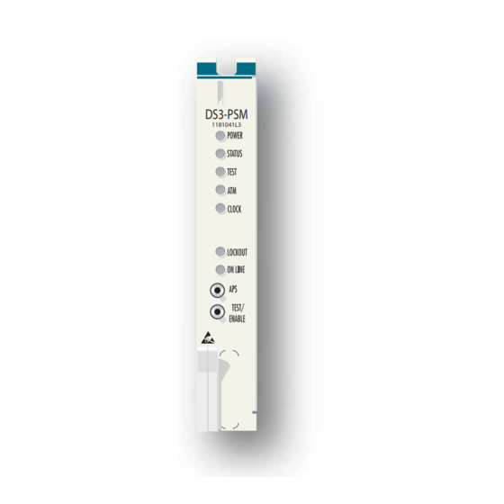
Total Access 3000 DSLAM DS3 Primary Switch Module GENERAL This practice is an installation and maintenance guide for the ADTRAN Total Access 3000 ® DSLAM DS3 Primary Switch Module (DS3-PSM). Figure 1 illustrates the DS3-PSM (P/N 1181041L3) front panel. DS3-PSM 1181041L3 Figure 1. -
Page 12: Description
Total Access 3000 DSLAM DS3 Primary Switch Module Installation and Maintenance Practice Description The DS3-PSM is a common plug-in module used in the High Density Expansion (HDX) archi- tecture. The DS3-PSM is an Asynchronous Transfer Mode (ATM) switch with the switching, policing and shaping functionality of a typical ATM switch, plus the added functionality to extend these functions across five additional expansion shelves. -
Page 13: Management
General Management The DS3-PSM is used in conjunction with the Primary Controller Unit (PCU) to support both local and remote management. Operation Administration Maintenance and Provisioning (OAM&P) tasks can be performed through the Operating System (OS) interface on the PCU. Remote management via Total Access Element Management System (EMS) using Simple Network Management Protocol (SNMP) is supported through the PCU. -
Page 14: Mde
Total Access 3000 DSLAM DS3 Primary Switch Module Installation and Maintenance Practice The Metallic Data Extension (MDE) bus is an ADTRAN proprietary, metallic, short range, high- speed interconnection bus between an ADTRAN Primary Total Access 3000 Shelf and up to five Expansion shelves. -
Page 15: Expansion Shelves
General Expansion Shelves The Expansion shelves can be populated with any standard access modules except for the following: • Total Access 3000/3010 DS3 Line Module (DS3 LM, P/N 1181450L1) • Total Access 3000/3010 OC-3 Line Module (OC-3 LM, P/N 1181454L1) Expansion Shelf MUX slots are populated with ESMs where two are needed for 1:1 redundancy. -
Page 16: Features
Total Access 3000 DSLAM DS3 Primary Switch Module Installation and Maintenance Practice Features The basic features of the DS3-PSM include the following: • Provides DS3 interface with the following standard features: – Supports the M13 or C-bit parity DS3 formats –... -
Page 17: Operation
Operation OPERATION The DS3-PSM serves as an ATM network interface. The ATM cells are packaged at the access module and then either switched to another access slot or transported to the Wide Area Network (WAN) where they are direct mapped into an unchannelized DS3 pipe. The DS3-PSM supports 224 local subscribers out of a single 23-inch Total Access 3000 chassis or up to 1344 subscribers with local subtending. -
Page 18: Remote Alarm Indication (Rai)
Total Access 3000 DSLAM DS3 Primary Switch Module Installation and Maintenance Practice Remote Alarm Indication (RAI) The DS3-PSM transmits RAI to the far end in the following circumstances: • Valid framing cannot be identified • DS3-PSM is receiving AIS on the incoming DS3 signal •... -
Page 19: Front Panel Leds
Operation Front Panel LEDs The DS3-PSM provides front panel LEDs to display status information. The DS3-PSM LEDs and status descriptions are shown in Table Table 3. Front Panel LEDs Label Status Description No power is present on the module POWER Green Module has power and is In Service Yellow... -
Page 20: Pushbuttons
Total Access 3000 DSLAM DS3 Primary Switch Module Installation and Maintenance Practice Pushbuttons The DS3-PSM is equipped with the pushbuttons described in Table Table 4. Pushbuttons Switch Description When pressed with the pushbutton from the offline unit, a switch is... -
Page 21: Instructions For Installing The Module
Installation Instructions for Installing the Module To install the DS3-PSM, perform the following steps: 1. If present, remove the Common Module Blank from the appropriate common module (A or B) slot of the Total Access 3000/3010 chassis. 2. Pull the ejector latch, located on the lower left-hand side of the DS3-PSM front panel, from its closed position. -
Page 22: Provisioning
Total Access 3000 DSLAM DS3 Primary Switch Module Installation and Maintenance Practice PROVISIONING All provisioning takes place through the DS3-PSM/PCU communication link via DS3-PSM menus and/or SNMP access to the DS3-PSM. Onboard switches or jumpers are not provided. The DS3-PSM retains all provisionable data for the ESMs on its MDE link in a nonvolatile memory device. - Page 23 Provisioning Table 5. Default Provisioning Options (Continued) Provisioning Option Available Options Default Settings Line Length (meters) 0-64000 Primary Timing LOCAL; LOOP; PLCP; LOOP (Bank Timing) EXT BITS B; EXT BITS C; LINECARD Secondary Timing NONE; LOCAL; LOOP; PLCP; NONE EXT BITS B; EXT BITS C; LINECARD Line Code B3ZS...
- Page 24 Total Access 3000 DSLAM DS3 Primary Switch Module Installation and Maintenance Practice Table 5. Default Provisioning Options (Continued) Provisioning Option Available Options Default Settings Neighbor Name User defined blank Neighbor IP Address User defined 0.0.0.0 ATM Provisioning (MGMT Port) Port ID...
-
Page 25: User Interface
User Interface USER INTERFACE This section provides detailed information on the following: • “Menu Structure” on page 15 • “Menus” on page 15 • “Menu Navigation” on page 16 • “Menu Trees” on page 20 • “Menu Descriptions” on page 31 Menu Structure The menu structure for the DS3-PSM is a layered menu tree. -
Page 26: Menu Navigation
Total Access 3000 DSLAM DS3 Primary Switch Module Installation and Maintenance Practice Menu Navigation Basic menu navigation is accomplished by selecting the desired option number and then pressing . To return to the previous menu, press the (escape) key. To access the... - Page 27 User Interface Table 7. Menu Specific Hot Keys (Continued) Hot Key Description ATM Provisioning (DS3) Menu This hot key is used to display the “ILMI Provisioning Screen”. Traffic Descriptor Screen This hot key is used to display the “Create Traffic Descriptor Screen”.
- Page 28 Total Access 3000 DSLAM DS3 Primary Switch Module Installation and Maintenance Practice Table 7. Menu Specific Hot Keys (Continued) Hot Key Description This hot key is used to set the path to one of the following options: • PVC • PVP ATM Monitor Sessions Screen This hot key is used to display information for the next shelf in the series.
- Page 29 User Interface Table 7. Menu Specific Hot Keys (Continued) Hot Key Description DS3 ATM Stats Screen This hot key is used to reset the statistics for the specific port being viewed. MGMT ATM Stats Screen This hot key is used to reset the statistics for the specific port being viewed. Port ATM Stats Screen This hot key is used to reset the statistics for the specific port being viewed.
-
Page 30: Menu Trees
Total Access 3000 DSLAM DS3 Primary Switch Module Installation and Maintenance Practice MENU TREES There are a number of menu screens designed to aid in the maintenance and troubleshooting of the DS3-PSM. The DS3-PSM menu tree (see Figure 3 through... -
Page 31: Figure 4. Provisioning Menu Tree
Menu Trees 1. Advanced Provisioning 1. C-BIT DIRECT MAP 2. DS3 and Timing 1. Framing Provisioning 2. C-BIT PLCP 2. Line Length (meters) 3. M23 DIRECT MAP 4. M23 PLCP 1. Local 1. Bank Timing 3. Primary Timing 2. Loop 2. -
Page 32: Figure 5. Advanced Provisioning Menu Tree
Total Access 3000 DSLAM DS3 Primary Switch Module Installation and Maintenance Practice 1. IN SERVICE 1. Service State 2. OUT OF SERVICE, MAINTENANCE 2. OAM Identification Maximum Network VC/VPs 1. ENABLE 4. Linked Provisioning 2. DISABLE 5. Reserved VoiceVPI 1. ENABLED 1. -
Page 33: Figure 6. Atm Provisioning Slot/Port Menu Tree
Menu Trees 1. Port ID 1. IN SERVICE 2. Service Mode 2. OUT OF SERVICE, MAINTENANCE Card Type Port Tx Rate Port Rx Rate 1. UNI 6. Port Type 2. NNI 1. Enable Scrambler 2. Disable 1. BELLCORE (Unassigned Cell) 8. -
Page 34: Figure 7. Atm Provisioning (Ds3) Menu Tree
Total Access 3000 DSLAM DS3 Primary Switch Module Installation and Maintenance Practice 1. Port ID 1. IN SERVICE 2. Service State 2. OUT OF SERVICE, MAINTENANCE 3. OUT OF SERVICE, UNASSIGNED 1. UNI 3. Port Type 2. NNI 4. Scrambler 1. -
Page 35: Figure 8. Traffic Descriptor Menu Tree
Menu Trees Index Name Service Class Traffic Descriptor Type N - Next P - Previous 1. Name C - Create 1. CBR 2. Service Category D - Duplicate 2. rtVBR R - Remove 3. nrtVBR M - Modify 4. UBR S - Show 1. -
Page 36: Figure 9. Vc/Vp Provisioning Menu Tree
Total Access 3000 DSLAM DS3 Primary Switch Module Installation and Maintenance Practice Index Status Type Endpoint 1 SH/SL/PO Endpoint 2 SH/SL/PO SRV-CL N - Next P - Previous 1. Forward Traffic Descriptor (1->2) C - Create PVC 2. Backward Traffic Descriptor (2->1) R - Remove PVC 3. -
Page 37: Figure 10. Software Upgrade Menu Tree
Menu Trees 1. YMODEM 1. Transfer Protocol 2. TFTP 1. 115.2k 2. SCU to MUX Baud Rate 2. 57.6k 3. 38.4k 3. TFTP File Name 4. Start Transfer 5. Restore Card Factory Defaults and Reset 6. Restart Card with Latest Code App Software Rev App Code Chksum Boot Software Rev... -
Page 38: Figure 11. Test Menu Tree
Total Access 3000 DSLAM DS3 Primary Switch Module Installation and Maintenance Practice 1. DS3 Loopback 1. No Loopback Test 1. DS3 Loopback 2. Network Payload Loopback 3. Network Loopback Index 4. Local Payload Loopback 2. PVC/PVP Test Status 5. Dual Loopback Type 6. -
Page 39: Figure 12. Performance Monitoring Menu Tree
Menu Trees 1. Code Violation 1. Daily 2. Errored Sec 3. Sev Erred Sec 4. Loss of Sig Sec 5. Code Violation 6. Code Violation CP-P 7. Errored Sec 1. DS3 LIU 8. Errored Sec CP-P Performance Monitoring 9. Sev Erred Sec 10. -
Page 40: Figure 13. Atm Performance Monitoring Menu Tree
Total Access 3000 DSLAM DS3 Primary Switch Module Installation and Maintenance Practice 1. DS3 ATM Stats Tx Cells 2. MGMT ATM Stats Rx Cells 3. Port ATM Stats (Slot/Port) Rx Cells w/Header Errors Index 4. VC/VP ATM Stats Name Endpoint 1... -
Page 41: Menu Descriptions
Menu Trees Menu Descriptions The DS3-PSM main menu (see Figure 14) is used to provide access to the module. The main menu options have several functions and submenus that identify and provide access to specific operations and parameters. Shelf: 1 Slot: B Total Access System MM/DD/YY HH:MM ONLINE... -
Page 42: Configuration Screen
For instance, the Common Language Equipment Identifier (CLEI) Code and Part Number can be used to search for related information on the ADTRAN website or to order additional parts. The software revision may be required when calling ADTRAN Technical Support. -
Page 43: Provisioning Menu
Menu Trees Provisioning Menu The Provisioning menu (see Figure 16) provides access to the provisioning submenus. Shelf: 1 Slot: B Total Access System MM/DD/YY HH:MM ONLINE DS3-PSM Advanced Provisioning DS3 and Timing Provisioning ATM Provisioning (PORT) ATM Provisioning (DS3) ATM Provisioning (MGMT Port) Traffic Descriptor Provisioning VC/VP Provisioning PNNI Switch Provisioning - Base menu... - Page 44 Total Access 3000 DSLAM DS3 Primary Switch Module Installation and Maintenance Practice Table 10. Provisioning Menu Options (Continued) Option Description Function PNNI Switch Provisioning - This option displays the “PNNI Switch Provisioning - Base Base menu Menu” on page 78.
-
Page 45: Psm Advanced Provisioning Menu
Menu Trees PSM Advanced Provisioning Menu The PSM Advanced Provisioning menu (see Figure 17) is used to provision PSM specific and subscriber interface options. Shelf: 1 Slot: B Total Access System MM/DD/YY HH:MM ONLINE PSM Advanced Provisioning PSM Specific Options Service State : IN SERVICE OAM Identification... - Page 46 Total Access 3000 DSLAM DS3 Primary Switch Module Installation and Maintenance Practice Table 11. PSM Advanced Provisioning Menu Options (Continued) Option Description Function Reserved Voice VPI This option is used to set the Reserved Voice Virtual Path Identifier (Reserved Voice VPI) to a number between 0 and 1000.
-
Page 47: System Buffer, Cac, & Policing Options Menu
Menu Trees System Buffer, CAC, & Policing Options Menu The System Buffer, CAC, & Policing Options menu (see Figure 18) used to display and provision parameters that control AIS/RDI generation, cell policing, overbooking, sharing, class scheduling, and traffic shaping. This menu also provides access to similar Loop, WAN, and Port menus via the hot keys. -
Page 48: Table 13. System Buffer, Cac, & Policing Menu Options
Total Access 3000 DSLAM DS3 Primary Switch Module Installation and Maintenance Practice Table 13. System Buffer, CAC, & Policing Menu Options Option Description Function Policing This option is used to enable or disable policing. Default Input CDVT This option is used to set the Default Input CDVT value to a number from 0 to 107300000. -
Page 49: Table 14. System Buffer, Cac, & Policing Options Menu Hot Keys
Menu Trees Table 13. System Buffer, CAC, & Policing Menu Options (Continued) Option Description Function rtVBR Traffic Shaping This option is used to enable or disable rtVBR Traffic Shaping. nrtVBR Traffic Shaping This option is used to enable or disable nrtVBR Traffic Shaping. -
Page 50: Wan Direction (Network) Buffer, Cac, & Policing Options Menu
Total Access 3000 DSLAM DS3 Primary Switch Module Installation and Maintenance Practice WAN Direction (Network) Buffer, CAC, & Policing Options Menu The WAN Direction (Network) Buffer, CAC, & Policing Options menu (see Figure 19) is used to manage Wide Area Network (WAN) settings. This menu is accessed by pressing the hot key on any of the Buffer, CAC, &... -
Page 51: Table 16. Wan Direction (Network) Buffer, Cac, & Policing Options Menu Hot Keys
Menu Trees Table 15. WAN Direction Buffer, CAC, & Policing Options Menu Options (Continued) Option Description Function Maximum Buffer This option is used to set the Maximum Buffer Threshold to Threshold a value from 1 to 262143. Override This option is used to control nrtVBR Sharing % setting override. -
Page 52: Loop Direction Buffer, Cac, & Policing Options Menu
Total Access 3000 DSLAM DS3 Primary Switch Module Installation and Maintenance Practice Loop Direction Buffer, CAC, & Policing Options Menu The Loop Direction Buffer, CAC, & Policing Options menu (see Figure 20) is used to manage Loop settings. This menu is accessed by pressing the hot key on any of the Buffer, CAC, &... -
Page 53: Table 18. Loop Direction Buffer, Cac, & Policing Options Menu Hot Keys
Menu Trees Table 17. Loop Direction Buffer, CAC, & Policing Options Menu Options (Continued) Option Description Function Maximum Buffer This option is used to set the Maximum Buffer Threshold to Threshold a value from 1 to 262143. Override This option is used to control nrtVBR Sharing % setting override. -
Page 54: Shelf # Slot # Port # Buffer, Cac, & Policing Options Menu
Total Access 3000 DSLAM DS3 Primary Switch Module Installation and Maintenance Practice Shelf # Slot # Port # Buffer, CAC, & Policing Options Menu The Shelf # Slot # Port # Buffer, CAC, & Policing Options menu (see Figure 21) is used to manage Port settings for the selected port. -
Page 55: Table 20. Shelf # Slot # Port # Buffer, Cac, & Policing Options Menu Hot Keys
Menu Trees Table 19. Shelf # Slot # Port # Buffer, CAC, & Policing Options Menu Options (Continued) Option Description Function Override This option is used to control the Maximum Buffer Threshold setting override. Override This option is used to control CBR Class Scheduling override. -
Page 56: Alarms Provisioning Menu
Total Access 3000 DSLAM DS3 Primary Switch Module Installation and Maintenance Practice Alarms Provisioning Menu The Alarms Provisioning menu (see Figure 22) is used to provision timing, cell delineation, and DS3 alarms. Shelf: 1 Slot: B Total Access System MM/DD/YY HH:MM... -
Page 57: Ds3 And Timing Provisioning Menu
Menu Trees DS3 and Timing Provisioning Menu The DS3 and Timing Provisioning menu (see Figure 23) is used to set parameters to govern the network side of the DS3-PSM. Shelf: 1 Slot: B Total Access System MM/DD/YY HH:MM ONLINE DS3 and Timing Provisioning Framing : C-BIT DIRECT MAP Line Length(meters) : 15... - Page 58 Total Access 3000 DSLAM DS3 Primary Switch Module Installation and Maintenance Practice Table 22. DS3 and Timing Provisioning Menu Options (Continued) Option Description Function Ext Bits Mode This option is used to set the type of signal connected to External Bit B and C on the Total Access 3000 shelf. The options are as follows: •...
-
Page 59: Framing Menu
Menu Trees Framing Menu The Framing menu (see Figure 24) is used to set the framing of the DS3 data stream. Shelf: 1 Slot: B Total Access System MM/DD/YY HH:MM ONLINE DS3-PSM Framing: C-BIT DIRECT MAP C-BIT DIRECT MAP C-BIT PLCP M23 DIRECT MAP M23 PLCP Selection:... -
Page 60: Primary Timing Menu
Total Access 3000 DSLAM DS3 Primary Switch Module Installation and Maintenance Practice Primary Timing Menu The Primary Timing menu (see Figure 25) is used to set the clock source for the Total Access 3000 shelf. Shelf: 1 Slot: B Total Access System... -
Page 61: Secondary Timing Menu
Menu Trees Secondary Timing Menu The Secondary Timing menu (see Figure 26) is used to set an alternative clock source for the Total Access 3000 shelf in the event the primary clock is lost or degraded. Shelf: 1 Slot: B Total Access System MM/DD/YY HH:MM ONLINE... -
Page 62: Atm Provisioning Screen - Shelf # Slot # Port # Menu
Total Access 3000 DSLAM DS3 Primary Switch Module Installation and Maintenance Practice ATM Provisioning Screen - Shelf # Slot # Port # Menu The ATM Provisioning Screen - Shelf # Slot # Port # menu is displayed when the ATM Provi-... - Page 63 Menu Trees Table 26. ATM Provisioning Screen - Shelf # Slot # Port # Menu Options (Continued) Option Description Function Card Type This field displays the type of module serviced by this slot number. Port Tx Rate This field displays the transmit (upstream) data rate on the selected module.
-
Page 64: Table 27. Atm Provisioning Screen - Shelf # Slot # Port # Menu Hot Keys
Total Access 3000 DSLAM DS3 Primary Switch Module Installation and Maintenance Practice Table 26. ATM Provisioning Screen - Shelf # Slot # Port # Menu Options (Continued) Option Description Function Neighbor IP Address This option is used to set and display the Neighbor IP Address in the format of xxx.xxx.xxx.xxx. -
Page 65: Atm Provisioning Screen - Shelf # Slot # Port # (Pnni Port Options) Menu
Menu Trees ATM Provisioning Screen - Shelf # Slot # Port # (PNNI Port Options) Menu The ATM Provisioning Screen - Shelf # Slot # Port # (PNNI Port Options) menu (see Figure is used to set port parameters for Private Network-to-Network Interface (PNNI) interoperability. Shelf: 1 Slot: B Total Access System MM/DD/YY HH:MM... - Page 66 Total Access 3000 DSLAM DS3 Primary Switch Module Installation and Maintenance Practice Table 28. ATM Provisioning Screen - Shelf # Slot # Port # (PNNI Port Options) Menu Options (Continued) Option Description Function Admin weight RT VBR This option is used to set the Admin weight Real Time Variable Bit Rate (RT VBR) value to a number from 1 to 16777215.
-
Page 67: Ilmi Provisioning Screen
Menu Trees ILMI Provisioning Screen The ILMI Provisioning Screen (see Figure 29) is used to set Interim Local Management Interface (ILMI) provisioning settings. The ILMI Provisioning Screen is accessed by pressing hot key on the ATM Provisioning Screen - Shelf # Slot # Port # menu. Shelf: 1 Slot: B Total Access System MM/DD/YY HH:MM... - Page 68 Total Access 3000 DSLAM DS3 Primary Switch Module Installation and Maintenance Practice Table 29. ILMI Provisioning Screen Options (Continued) Option Description Function UNI Type This option is used to set the User-to-Network Interface (UNI) Type to one of the following types: •...
-
Page 69: Atm Provisioning Screen - Ds3 Port Menu
Menu Trees ATM Provisioning Screen - DS3 Port Menu The ATM Provisioning Screen - DS3 Port menu (see Figure 30) is used to provision DS3 settings. Shelf: 1 Slot: B Total Access System MM/DD/YY HH:MM ONLINE ATM PROVISIONING SCREEN DS3 PORT Port ID : DS3 PORT Service State... - Page 70 Total Access 3000 DSLAM DS3 Primary Switch Module Installation and Maintenance Practice Table 30. ATM Provisioning Screen - DS3 Port Menu Options (Continued) Option Description Function Scrambler This option is used to enable or disable scrambling of the ATM cell payload.
- Page 71 Menu Trees Table 30. ATM Provisioning Screen - DS3 Port Menu Options (Continued) Option Description Function Restore Factory Defaults This option is used to restore the DS3 provisioning options to the following factory default values: • Service Mode: Out of Service-Maintenance •...
-
Page 72: Atm Provisioning Screen - Mgmt Port Menu
Total Access 3000 DSLAM DS3 Primary Switch Module Installation and Maintenance Practice ATM Provisioning Screen - MGMT Port Menu The ATM Provisioning Screen - MGMT Port menu (see Figure 31) is used to provision the management port interface parameters. Shelf: 1 Slot: B... - Page 73 Menu Trees Table 31. ATM Provisioning Screen - MGMT Port Menu Options (Continued) Option Description Function Maximum VCI Bits This field displays the maximum VCI Bits value assigned to the port. Physical Address This option is used to set and display the Physical Address (often the ATM address) of the management port.
- Page 74 Total Access 3000 DSLAM DS3 Primary Switch Module Installation and Maintenance Practice Table 31. ATM Provisioning Screen - MGMT Port Menu Options (Continued) Option Description Function Restore Factory Defaults This option is used to restore the DS3 provisioning options to the following factory default values: •...
-
Page 75: Traffic Descriptor Screen
Menu Trees Traffic Descriptor Screen The Traffic Descriptor Screen (see Figure 32) displays traffic descriptor information. A traffic descriptor is a set of parameters that determine how packets of data are handled. From the Traffic Descriptor Screen, a traffic descriptor can be created, edited, viewed, or removed through the use of the hot keys listed at the bottom of the screen. -
Page 76: Table 33. Traffic Descriptor Screen Hot Keys
Total Access 3000 DSLAM DS3 Primary Switch Module Installation and Maintenance Practice Table 33. Traffic Descriptor Screen Hot Keys Hot Key Description This hot key is used to display the “Create Traffic Descriptor Screen” on page 67. This hot key is used to duplicate an existing traffic descriptor. -
Page 77: Create Traffic Descriptor Screen
Menu Trees Create Traffic Descriptor Screen The Create Traffic Descriptor Screen (see Figure 33) is used to create a traffic descriptor. The Create Traffic Descriptor Screen is accessed by typing the hot key on the Traffic Descriptor Screen. A traffic descriptor must be created before a PVC can be provisioned. Shelf: 1 Slot: B Total Access System MM/DD/YY HH:MM... -
Page 78: Table 34. Create Traffic Descriptor Screen Options
Total Access 3000 DSLAM DS3 Primary Switch Module Installation and Maintenance Practice Table 34. Create Traffic Descriptor Screen Options Option Description Function Name This option is used to name the new traffic descriptor using up to ten alphanumeric characters. Service Category This option is used to select a service category. -
Page 79: Vc/Vp Provisioning Screen
Menu Trees VC/VP Provisioning Screen The VC/VP Provisioning screen (see Figure 34) displays PVC information. A PVC is a virtual connection of two endpoints. From the VC/VP Provisioning screen, a PVC can be created, edited, viewed, enabled, disabled, or removed. Shelf: 1 Slot: B Total Access System MM/DD/YY HH:MM... -
Page 80: Table 36. Vc/Vp Provisioning Screen Hot Keys
Total Access 3000 DSLAM DS3 Primary Switch Module Installation and Maintenance Practice Table 35. VC/VP Provisioning Screen Fields (Continued) Field Description This field displays the current VPI value of the VC/VP Endpoint 2. This field displays the current VCI value of the VC/VP Endpoint 2. -
Page 81: Detailed Pvc Information Screen
Menu Trees Detailed PVC Information Screen The Detailed PVC Information screen (see Figure 35) is read-only and displays Detailed PVC Information. The Detailed PVC Information is accessed by entering the Index Number of the PVC to view from the VC/VP Provisioning screen. Shelf: 1 Slot: B Total Access System MM/DD/YY HH:MM... - Page 82 Total Access 3000 DSLAM DS3 Primary Switch Module Installation and Maintenance Practice Table 37. Detailed PVC Information Screen Fields (Continued) Field Function Endpoint #2 PORT Name This field displays the port associated with Endpoint 2. This field displays the VPI for EndPoint 2.
-
Page 83: Vc/Vp Provisioning - Create Pvc/Pvp Menu
Menu Trees VC/VP Provisioning - Create PVC/PVP Menu The VC/VP Provisioning - Create PVC/PVP menu (see Figure 36) is used to create a PVC or a PVP, which are virtual connections of two endpoints. Shelf: 1 Slot: B Total Access System MM/DD/YY HH:MM ONLINE VC/VP PROVISIONING... -
Page 84: Table 38. Vc/Vp Provisioning - Create Pvc/Pvp Menu Options
Total Access 3000 DSLAM DS3 Primary Switch Module Installation and Maintenance Practice Table 38. VC/VP Provisioning - Create PVC/PVP Menu Options Option Description Function Fwd Traffic Descr. (1->2) Enter the index number or an alphanumeric string of up to ten characters corresponding to the appropriate Traffic Descriptor for this endpoint. - Page 85 Menu Trees Table 38. VC/VP Provisioning - Create PVC/PVP Menu Options (Continued) Option Description Function This option sets the VPI for Endpoint 2 and requires a numeric entry (0 to 255 when operating as a UNI or 0 to 4095 when operating as an NNI). This option sets the VCI for Endpoint 2 and requires a numeric entry (0 to 511 when operating as a UNI or 0 to 65535 when operating as an NNI).
-
Page 86: Table 39. Vc/Vp Provisioning - Create Pvc/Pvp Menu Hot Keys
Total Access 3000 DSLAM DS3 Primary Switch Module Installation and Maintenance Practice Table 39. VC/VP Provisioning - Create PVC/PVP Menu Hot Keys Hot Key Description This hot key is used to create a new PVC/PVP. This hot key is used to set the VC/VP name for a new PVC. -
Page 87: Search Through Vc/Vp List Menu
Menu Trees Search Through VC/VP List Menu The Search Through VC/VP List menu (see Table 37) is used to search existing PVCs by traffic descriptor or assigned port. Shelf: 1 Slot: B Total Access System MM/DD/YY HH:MM ONLINE SEARCH THROUGH VC/VP LIST Search for Loop Ports Search for DS3 Ports Search for MGMT Ports... -
Page 88: Pnni Switch Provisioning - Base Menu
Total Access 3000 DSLAM DS3 Primary Switch Module Installation and Maintenance Practice PNNI Switch Provisioning - Base Menu The PNNI Switch Provisioning - Base menu (see Figure 38) is used to disable Private Network- to-Network Interface (PNNI) options or display the Lowest level node menu. -
Page 89: Pnni Switch Provisioning - Lowest Level Node Menu
Menu Trees PNNI Switch Provisioning - Lowest Level Node Menu The PNNI Switch Provisioning - Lowest Level Node menu (see Figure 39) is used to provision Private Network-to-Network Interface (PNNI) options. Shelf: 1 Slot: B Total Access System MM/DD/YY HH:MM ONLINE PNNI switch provisioning - Lowest level node Admin status... -
Page 90: Software Upgrade Menu
Total Access 3000 DSLAM DS3 Primary Switch Module Installation and Maintenance Practice Software Upgrade Menu The Software Upgrade menu (see Figure 40) is used to upgrade software, verify code revision, and restore all options to factory defaults on the DS3-PSM. -
Page 91: Table 44. Software Upgrade Menu Hot Keys
Menu Trees Table 43. Software Upgrade Menu Options Option Description Function Restart Card with Latest This option reboots the DS3-PSM using the latest version of Code software that exists on the module. App Software Rev This field displays the current revision of the software. App Code Chksum This field displays the code checksum of the current software. -
Page 92: Mde Link Configuration Menu
Total Access 3000 DSLAM DS3 Primary Switch Module Installation and Maintenance Practice MDE Link Configuration Menu The MDE Link Configuration menu (see Figure 41) is used to display the MDE configuration status. This is a dynamic menu that displays available options based upon input. Shelf 1 is the Primary Shelf and shelves 2 through 6 are Expansion shelves. - Page 93 Menu Trees Table 45. MDE Link Configuration Menu Options (Continued) Option Description Function Shelf 1 Link Status This field displays the Shelf 1 link status as either Link Up or Link Down. Shelf 2 Link Status This field displays the Shelf 2 link status as either Link Up or Link Down.
-
Page 94: Ds3-Psm Status Menu
Total Access 3000 DSLAM DS3 Primary Switch Module Installation and Maintenance Practice DS3-PSM Status Menu The DS3-PSM Status menu (see Figure 42) provides access to the status submenus, which show current status information for both the network and loop side of the DS3-PSM. -
Page 95: Ds3 Csm Status Screen
Menu Trees DS3 CSM Status Screen The DS3 CSM Status screen (see Figure 43) displays DS3-PSM status information. Shelf: 1 Slot: B Total Access System MM/DD/YY HH:MM ONLINE DS3 CSM Status Framing : C-BIT DIRECT MAP Line Length(meters) : 15 Bank Timing : Primary (Ds3 Loop) Active Loops... - Page 96 Total Access 3000 DSLAM DS3 Primary Switch Module Installation and Maintenance Practice Table 47. DS3 CSM Status Screen Fields (Continued) Field Description APS Status If the module is in the Online status but in the Out of Service-Unas- (continued) signed state, it will not provide service.
-
Page 97: Line Card Status Screen
Menu Trees Line Card Status Screen The Line Card Status Screen (see Figure 44) displays DS3-PSM status information, and provides access to display individual access module and port status information. Shelf: 1 Slot: B Total Access System MM/DD/YY HH:MM ONLINE Line Card Status Screen Shelf: 1 Octal ADSL... -
Page 98: Port Status Screen
Total Access 3000 DSLAM DS3 Primary Switch Module Installation and Maintenance Practice Port Status Screen The Port Status Screen (see Figure 45) displays status information per port, for each of the access modules in the MDE Link configuration. When selected, a menu is displayed for selecting which access module status information to display. -
Page 99: Spvc Status Screen
Menu Trees SPVC Status Screen The SPVC Status screen (see Figure 46) displays current PVCs. Entering the index number associated with any PVC results in a display of status information for that PVC. Shelf: 1 Slot: B Total Access System MM/DD/YY HH:MM ONLINE SPVC STATUS... -
Page 100: Table 52. Spvc Status Screen Hot Keys
Total Access 3000 DSLAM DS3 Primary Switch Module Installation and Maintenance Practice Table 51. SPVC Status Screen Options (Continued) Field Description Endpoint 2 SH/SL/PO This field displays the shelf/slot/port location of the VC/VP Endpoint 2. This field displays the current VPI value of the VC/VP Endpoint 2. -
Page 101: Csm Alarms Screen
Menu Trees CSM Alarms Screen The CSM Alarms screen (see Figure 47) is read-only and displays currently active alarms for the DS3-PSM, including the date, time and a brief description of the alarm. An alarm is displayed until the condition that caused the alarm is cleared. NOTE This is not an alarm history log. -
Page 102: Table 54. Csm Alarms Screen Hot Keys
Total Access 3000 DSLAM DS3 Primary Switch Module Installation and Maintenance Practice Table 54. CSM Alarms Screen Hot Keys Hot Key Description This hot key is used to display the first page of alarms. This hot key is used to display the last page of alarms. -
Page 103: Test Menu
Menu Trees Test Menu The Test menu (see Figure 48) provides access to testing through submenus for loopback, PVC/PVP, and single access module cell generation tests. Shelf: 1 Slot: B Total Access System MM/DD/YY HH:MM ONLINE DS3-PSM DS3 Loopback Test PVC/PVP Test Single Card Cell Generation Test Selection:... -
Page 104: Csm Test Menu
Total Access 3000 DSLAM DS3 Primary Switch Module Installation and Maintenance Practice CSM Test Menu The CSM Test menu (see Figure 49) is used to access submenus to perform DS3 loopback tests and verify the integrity of the loop. The CSM Test menu is accessed by selecting DS3 Loopback Test from the Test menu. -
Page 105: Ds3 Loopbacks Menu
Menu Trees DS3 Loopbacks Menu The DS3 Loopbacks menu (see Figure 50) is used to access submenus to perform various DS3 loopback tests. Shelf: 1 Slot: B Total Access System MM/DD/YY HH:MM ONLINE DS3-PSM DS3 Loopbacks No Loopback Network Payload Loopback Network Loopback Local Payload Loopback Dual Loopback... - Page 106 Total Access 3000 DSLAM DS3 Primary Switch Module Installation and Maintenance Practice Table 57. DS3 Loopbacks Menu Options (Continued) Option Description Function LIU Digital Local Loopback This option is used to perform an LIU Digital Local Loopback test. This test sends a loopback toward the loop ports at the digital side of the LIU.
-
Page 107: Pvc/Pvp Test Screen
Menu Trees PVC/PVP Test Screen The PVC/PVP Test Screen (see Figure 51) displays VC/VP List information and provides access to the VC/VP Test Screen. Shelf: 1 Slot: B Total Access System MM/DD/YY HH:MM ONLINE VC/VP TEST SCREEN Total VC/VP: 1 Created VC/VP List Page 1 of 1... -
Page 108: Table 59. Vc/Vp Test Screen Hot Keys
Total Access 3000 DSLAM DS3 Primary Switch Module Installation and Maintenance Practice Table 58. PVC/PVP Test Screen Fields (Continued) Column Description Endpoint 2 SH/SL/PO This field displays the shelf/slot/port location of the VC/VP Endpoint 2. This field displays the current VPI value of the VC/VP Endpoint 2. -
Page 109: Vc/Vp Test Screen
Menu Trees VC/VP Test Screen The VC/VP Test Screen (see Figure 52) is used to perform OAM Loopback and cell insertion testing. Shelf: 1 Slot: B Total Access System MM/DD/YY HH:MM ONLINE VC/VP TEST SCREEN OAM LoopBack Insert Cells Selection: Figure 52. -
Page 110: Oam Loopback Test Screen
Total Access 3000 DSLAM DS3 Primary Switch Module Installation and Maintenance Practice OAM Loopback Test Screen The OAM Loopback Test Screen (see Figure 53) is used to perform OAM Loopback testing. The OAM Loopback test sends OAM Cells with the loopback indication bit set. The Remote OAM ID must be entered to identify at which connecting node the loopback should occur. - Page 111 Menu Trees Table 61. OAM Loopback Test Screen Options (Continued) Option Description Function Endpoint 2 (Top Level) SH/SL/PO This field displays the shelf/slot/port location of the VC/VP Endpoint 2. This field displays the current VPI value of the VC/VP Endpoint 2. This field displays the current VCI value of the VC/VP Endpoint 2.
- Page 112 Total Access 3000 DSLAM DS3 Primary Switch Module Installation and Maintenance Practice Table 61. OAM Loopback Test Screen Options (Continued) Option Description Function OAM Rx LoopBack Req This field displays the number of OAM Receive Loopback Requests for Endpoint 2.
-
Page 113: Insert Cell Test Screen
Menu Trees Insert Cell Test Screen The Insert Cell Test Screen (see Figure 54) is used to perform cell insertion testing. The Insert Cell Test provides a means to insert a cell with a predefined format on any PVC created and enabled. - Page 114 Total Access 3000 DSLAM DS3 Primary Switch Module Installation and Maintenance Practice Table 62. Insert Cell Test Screen Fields (Continued) Field Description Endpoint 2 (Top Level) SH/SL/PO This field displays the shelf/slot/port location of the VC/VP Endpoint 2. This field displays the current VPI value of the VC/VP Endpoint 2.
-
Page 115: Csm Test - Single Card Cell Generation Test Menu
Menu Trees CSM Test - Single Card Cell Generation Test Menu The CSM Test - Single Card Cell Generation Test menu (see Figure 55) is used to test the integrity of the backplane or physical line on the loop side. This menu is accessed by selecting Single Card Cell Generation Test from the Test menu. -
Page 116: Table 63. Single Card Cell Generation Test Menu Options
Total Access 3000 DSLAM DS3 Primary Switch Module Installation and Maintenance Practice Table 63. Single Card Cell Generation Test Menu Options Option Description Function Shelf 1, Slot 1 This option is used to input the shelf/slot number. Configuration This option is used to select a configuration. The options are as follows: •... -
Page 117: Performance Monitoring Menu
Menu Trees Performance Monitoring Menu The Performance Monitoring menu (see Figure 56) provides access to the DS3-PSM perfor- mance monitoring submenus. If performance intervals are enabled for the selected interface, then up to 24 hours of DS3 historical data can be viewed in various increments. NOTE Far-End Performance Monitoring is available in C-BIT framing mode only. -
Page 118: Table 65. Ds3 Performance Monitoring Definitions
Total Access 3000 DSLAM DS3 Primary Switch Module Installation and Maintenance Practice Table 65. DS3 Performance Monitoring Definitions Parameter Description Line Related Code Violation, Line This parameter indicates the number of Bipolar Violations (BPVs) and Excessive Zeros (EXZs) that have occurred during the accumu- lation period. - Page 119 Menu Trees Table 65. DS3 Performance Monitoring Definitions (Continued) Parameter Description Unavailable Second, CP-P This parameter indicates the number of seconds for which the DS3 path contains ten contiguous SESs while in C-bit framing. Severely Errored Frame, Path This parameter indicates the number of seconds containing one or more SEF defects or one or more AIS defects.
-
Page 120: Ds3 Csm Performance Monitoring Menu
Total Access 3000 DSLAM DS3 Primary Switch Module Installation and Maintenance Practice DS3 CSM Performance Monitoring Menu The DS3 CSM Performance Monitoring menu (see Figure 57) is used to access submenus to view DS3 performance monitoring data in daily, 24-hour, or 15 minute increments. -
Page 121: Ds3 Csm Daily Menu
Menu Trees DS3 CSM Daily Menu The DS3 CSM Daily menu (see Figure 57) is used to view DS3 performance monitoring statistics in daily increments. Shelf: 1 Slot: B Total Access System MM/DD/YY HH:MM ONLINE DS3 CSM Daily 10/26 10/25 10/24 10/23 10/22... - Page 122 Total Access 3000 DSLAM DS3 Primary Switch Module Installation and Maintenance Practice Table 67. DS3 CSM Daily Menu Options (Continued) Option Description Function Code Violation (CP-P) This option displays the DS3 CSM Daily, Code Violation (CP- P) screen, which displays only C-bit parity path code violation data in daily increments.
-
Page 123: Ds3 Csm Far-End Daily Menu
Menu Trees DS3 CSM Far-End Daily Menu The DS3 CSM Far-End Daily menu (see Figure 59) is used to view DS3 far-end performance monitoring statistics in daily increments. Shelf: 1 Slot: B Total Access System MM/DD/YY HH:MM ONLINE DS3 CSM Far-End Daily 10/26 10/25 10/24... -
Page 124: Atm Performance Monitoring Menu
Total Access 3000 DSLAM DS3 Primary Switch Module Installation and Maintenance Practice ATM Performance Monitoring Menu The ATM Performance Monitoring menu (see Figure 60) is used to access ATM statistics via submenus. Shelf: 1 Slot: B Total Access System MM/DD/YY HH:MM... -
Page 125: Port Performance - Ds3 Port Screen
Menu Trees Port Performance - DS3 Port Screen The Port Performance - DS3 Port screen (see Figure 61) is read-only and displays ATM statistics for the DS3 interface. Shelf: 1 Slot: B Total Access System MM/DD/YY HH:MM ONLINE PORT PERFORMANCE DS3 PORT TxCells RxCells... -
Page 126: Port Performance - Mgmt Port Screen
Total Access 3000 DSLAM DS3 Primary Switch Module Installation and Maintenance Practice Port Performance - MGMT Port Screen The Port Performance - MGMT Port screen (see Figure 62) is read-only and displays DS3 ATM statistics for the local Microprocessor Port interface. -
Page 127: Port Performance - Shelf # Slot #, Port # Screen
Menu Trees Port Performance - Shelf # Slot #, Port # Screen The Port Performance - Shelf # Slot #, Port # screen (see Figure 63) is read-only and displays DS3 ATM statistics for a specified loop port interface. Shelf: 1 Slot: B Total Access System MM/DD/YY HH:MM ONLINE... -
Page 128: Vc/Vp Performance - Created Vc/Vp List Screen
Total Access 3000 DSLAM DS3 Primary Switch Module Installation and Maintenance Practice VC/VP Performance - Created VC/VP List Screen The VC/VP Performance - Created VC/VP List screen (see Figure 64) is read-only and displays DS3 ATM statistics for a specified PVC/PVP. -
Page 129: Table 74. Vc/Vp Performance - Created Vc/Vp List Screen Hot Keys
Menu Trees The VC/VP Performance - Created VC/VP List screen hot keys are shown in Table Table 74. VC/VP Performance - Created VC/VP List Screen Hot Keys Hot Key Description This hot key displays the index information for the Index number that is input on NTER NDEX the Detailed PVC Information screen. -
Page 130: Vc/Vp Statistics Screen
Total Access 3000 DSLAM DS3 Primary Switch Module Installation and Maintenance Practice VC/VP Statistics Screen The VC/VP Statistics screen (see Figure 65) is read-only and displays DS3 ATM statistics for a specified PVC/PVP. The VC/VP Statistics screen is accessed by typing the Index Number of... - Page 131 Menu Trees Table 75. VC/VP Statistics Screen Fields (Continued) Field Description This field displays the current VCI value of the VC/VP Endpoint 2. SRV-CL This field displays the Service Class assigned to the PVC (defined by the traffic descriptor). Endpoint1 Tx Cells This field displays the number of user and OAM cells transmitted on this PVC/PVP.
- Page 132 Total Access 3000 DSLAM DS3 Primary Switch Module Installation and Maintenance Practice Table 75. VC/VP Statistics Screen Fields (Continued) Field Description Sar Timeouts This field displays the number of times that the Segmentation Reassembly (Sar) exceeded the reassembly time limit.
-
Page 133: Monitor Session List Screen
Menu Trees Monitor Session List Screen The Monitor Session List screen (see Figure 66) displays ATM statistics. Shelf: 1 Slot: B Total Access System MM/DD/YY HH:MM ONLINE Monitor Session List Active sessions: 0 Page 1 of 1 INDEX STATUS SCOPE NAME N-Next,P-Prev,C-Create,R-Remove,E-Enable,D-Disable, or Index Figure 66. - Page 134 Total Access 3000 DSLAM DS3 Primary Switch Module Installation and Maintenance Practice Table 77. Monitor Session List Screen Hot Keys (Continued) Hot Key Description Enter the Index number for a corresponding Monitor Session to display the details NDEX of that Monitor Session.
-
Page 135: Protection Configuration Menu
Menu Trees Protection Configuration Menu The Protection Configuration menu (see Figure 67) is used to provision and manage Automatic Protection Switching (APS) functionality. Shelf: 1 Slot: B Total Access System MM/DD/YY HH:MM ONLINE Protection Configuration Operational Status : ONLINE APS Lockout Status : ALLOW Perform APS switch Selection:... -
Page 136: Maintenance
Total Access 3000 DSLAM DS3 Primary Switch Module Installation and Maintenance Practice MAINTENANCE The DS3-PSM does not require routine maintenance for normal operation. ADTRAN does not recommend that repairs be attempted in the field. Repair services may be obtained by returning the defective unit to ADTRAN. Refer to “Appendix A, Warranty”... -
Page 137: Warranty
Appendix A Warranty WARRANTY AND CUSTOMER SERVICE ADTRAN will replace or repair this product within the warranty period if it does not meet its published specifications or fails while in service. Warranty information can be found at www.adtran.com/warranty. Refer to the following subsections for sales, support, Customer and Product Service (CAPS) requests, or further information. - Page 138 ® Carrier Networks Division 901 Explorer Blvd. Huntsville, AL 35806...
Need help?
Do you have a question about the Total Access 3000 DSLAM and is the answer not in the manual?
Questions and answers