Table of Contents
Advertisement
Quick Links
Advertisement
Table of Contents

Related Manuals for Ganz Digimaster DR4N-Lite


Summary of Contents for Ganz Digimaster DR4N-Lite
-
Page 2: Table Of Contents
S P E C I F I C A T I O N & O R G A N I Z A T I O N - - - - - - - - - - - - - - - - - - - - - - - - - - - - - - - - - - - - - - - - - - - - - - - - - - S p e c i f i c a t i o n s - - - - - - - - - - - - - - - - - - - - - - - - - - - - - - - - - - - - - - - - - - - - - - - - - - - - - - - - - P r o d u c t C o n t e n t s L i s t... - Page 3 R E C O R D M E N U - - - - - - - - - - - - - - - - - - - - - - - - - - - - - - - - - - - - - - - - - - - - - - - - - - - - - - - - - - - - R e c o r d i n g o p e r a t i o n s - - - - - - - - - - - - - - - - - - - - - - - - - - - - - - - - - - - - - - - - - - - - - - - - - - -...
- Page 4 This manual applies to the DR4N-Lite. This manual describes the external features of GANZ DIGIMASTER, part names, correct connection methods for supported domes or pan/tilt receivers, control devices, peripheral devices and the system setup instructions. It is important to note here that some features, figures, pictures and references can only be applied to just one model.
- Page 5 CBC reserves all copyrights of registered trademarks in this manual. Please be aware of the following precautions before installing the DVR. Avoid positioning the GANZ DIGIMASTER in any place where the unit may come into contact with moisture, dust, or soot.
- Page 6 The following are warnings and cautions to ensure user safety and prevent property damage. Please read the information below thoroughly.
-
Page 10: Important Safety Instructions
Important Safety Instructions 1) Read these instructions. 2) Keep these instructions. 3) Read all warnings. 4) Follow all instructions. 5) Do not use this apparatus near water. 6) Clean only with a dry cloth. 7) Do not block any of the ventilation openings. Install in accordance with the manufacturer's instructions. -
Page 11: S P E C I F I C A T I O N
Specifications & Organization 1. Specifications Video standard PAL/NTSC 2-way Audio conference Audio Monitor display Real time:25 Fps (PAL), 30Fps(NTSC) per camera Programmable Covert camera operation Event/Log search limitation user login/out, config changes, remote access, connects/disconnects Daily, Weekly adjust specific Hr per channel Record Scheduling Remote Access TCP/IP, View, Search, Recording &... -
Page 12: P R O D U C T C O N T E N T S L I S
2. Product Contents List Please check if all the product contents are present after opening the package. DR4N-Lite 12V Adaptor (With ac cord) Remote Agent Instruction Manual Remote Controller PS2 Mouse Installation CD (With Battery) 3. System Organization... -
Page 13: P R O D U C T D E S C R I P T I O
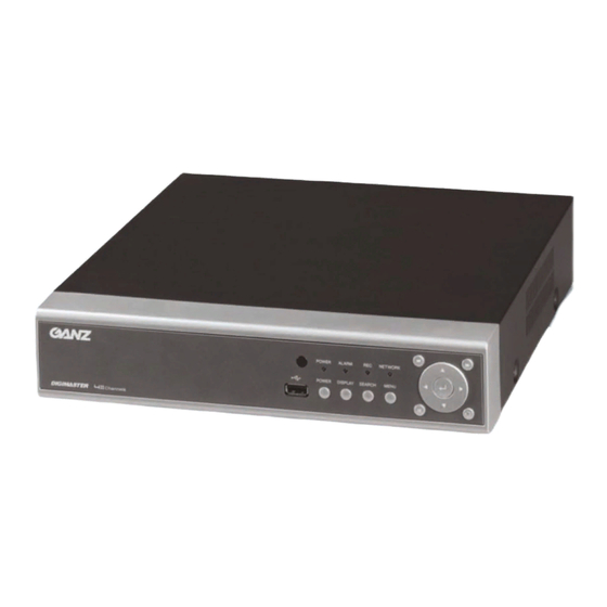
Product Description 1. Front Panel - USB PORT: Port for USB devices, for mouse and backup. - POWER: Turn on power of system. - DISPLAY: Select display mode between split and full mode. - SEARCH: Enter to search menu - MENU: Enter to system configuration menu. - NAVIGATION KEY: use for navigating on menu or control PTZ. - Page 14 SYSTEM CONFIGURE – Remote Controller CONNECT & POWER ON • Connect up to 4 CAMERA INPUTS as necessary. • Connect one or more monitors to the DVR using the COMPOSITE, VGA connections • Connect power to the DVR. The DVR checks for proper power connection and emits one beep. Press the POWER BUTTON on the front panel of the DVR to begin operation.
-
Page 15: L I V E D I S P L A
After startup diagnostics are complete, the operator must logon to the system. The default user name is ‘ADMIN’. the default password of ‘1234’ and press the ENTER button. Double click on the Password tap then the Virtual Keyboard will be appeared. -
Page 16: M A N U A L R E C O R D I N
Click the right mouse button on the Live Display screen and click the SEQUENCE menu. All the display modes are static with the exception of the sequence mode. In this mode, the sequence symbol ( ) is displayed and each channel is shown in full screen for a set period of time before switching to the next channel. -
Page 17: K E Y L O C K F U N C T I O
Key Lock Function Click the right mouse button on the Live Display screen and click the LOGOFF menu. An operator with ADMIN rights can choose to lock the DVR front panel to prevent any unauthorized control. Select the KEYLOCK button and YES. PTZ Camera Control Click the right mouse button on the Live Display screen and click the PTZ menu. -
Page 18: S Y S T E M S E T U
Click the PRESET & SWING menu. All menus can be controlled by navigation key and pressing the mouse click. SYSTEM SETUP Click the right mouse button on the Live Display screen and click the SETUP menu. DISPLAY : To setup the various display options, highlight DISPLAY and press ENTER. DISPLAY - OSD Click the OSD menu and click the ON/OFF menu. -
Page 19: C A M E R A T I T L
CAMERA TITLE : Determines whether the camera title is displayed. EVENT ICON : Determines whether the DVR recording status is shown at the top right of each channel display window. BORDER : Determines whether there is a border around each channel in multi screen display mode. MOTION SENSOR DISPLAY : If false motion recording is occurring, the operator can use this feature to determine and rectify the cause in realtime. - Page 20 Use the CURSOR KEYS to navigate to the option required. Press ENTER to select the option (the cursor changes to orange) and use the CURSOR KEYS to change the setting. Press ENTER to save the setting or RETURN to cancel. CAMERA To setup the various camera options, highlight CAMERA and press ENTER.
- Page 21 Click the each value by button. The selected channel is displayed in full screen. BRIGHTNESS, CONTRAST, TINT and COLOUR can be changed as necessary. To modify a different channel, highlight CAMERA and choose the desired channel. Press RETURN when all changes are completed. DISPLAY : PTZ SETUP Click the PTZ SETUP menu and click the each value on the ADDRESS, PROTOCOL and BAUD RATE menu.
- Page 22 PTZ properties can also be adjusted for each channel by selecting the icon and pressing ENTER. Note that some settings, such as AUTO FOCUS, may not be compatible with particular PTZ equipment. If this is the case, changing this value will have no effect on PTZ control. DISPLAY : MOTION SENSOR Click the MOTION SENSOR menu and decide the value on the SENSITIVITY menu.
- Page 23 To quickly select or deselect the entire grid, click the right mouse button and click SELECT ALL or DESELECT ALL menu. Or press RETURN to bring up the motion menu to select or deselect the entire grid,. Choose SELECT ALL or DESELECT ALL as appropriate. Drag the grid by the left mouse.
-
Page 24: S O U N
SOUND To setup the various sound options, highlight SOUND and press ENTER. SOUND : AUDIO Click the AUDIO menu and click the ON/OFF menu. Then, click the button for ON/OFF. LIVE AUDIO : When it is set to ON, the selected audio channel can be monitored on the AUDIO OUTPUT. AUDIO MONITORING CHANNEL : Specify which one of the 4 AUDIO INPUTS is routed to the AUDIO OUTPUT. - Page 25 SYSTEM To setup the various system options, highlight SYSTEM and press ENTER. DATE / TIME Click the DATE / TIME menu and click the ON/OFF menu. Then, click the button for ON/OFF. DATE TIME : Allows the operator to set or modify the current date & time. DATE FORMAT : Determines how the date is displayed.
- Page 26 SYSTEM : NETWORK Press the NETWORK menu and click the ON/OFF menu. Then, click the button for ON/OFF. DHCP : When enabled, the DVR will obtain an IP address automatically if connected to a DHCP server or router. DDNS : When enabled, the DVR can be accessed through a Dynamic DNS server. Commonly used if a broadband connection does not have a static IP address.
- Page 27 SYSTEM : MAIL Press the MAIL menu and click ON/OFF menu. Then, click the button for ON/OFF. SERVER : The SMTP outbound email server that should be used to send email notifications. PORT : The outbound email port number. SECURITY : Set to OFF if the SERVER does not require a username and password to connect. USER : Enter a username to identify the DVR in email messages.
- Page 28 Double click the ADD button. To add the new user, press the ADD button. USER ID: Edit the user ID using the virtual keyboard. PASSWORD: Change the password using the virtual keyboard. GROUP: Users can belong to one of two groups - MANAGER or USER. (The user nr of ADMIN group is only one.) E-MAIL: Enter the user’s email address if email notification is required.
- Page 29 SYSTEM: SYSTEM MANAGEMENT Click the SYSTEM MANAGEMENT menu. SYSTEM INFORMATION - IP ADDRESS: Shows either the manual IP address entered in NETWORK setup or the IP address assigned by a DHCP server if enabled. - MAC ADDRESS: Shows the MAC (Media Access Control) address of the DVR. It is unique – no other network device has this MAC address.
- Page 30 SYSTEM NAME : A system name of up to 15 characters can be defined. It is used so that notification emails can be identified. F/W UPDATE : Firmware updates may be released periodically to enhance system performance and add extra features. The operator can upgrade the firmware using a USB memory stick. After finishing the upgrade, system will be rebooted.
- Page 31 4) After finishing, system is rebooted. 5) After rebooting one time, system will ask to reboot again with below pop-up window. Press “OK” and system reboot again. After finishing reboot, F/W upgrade is finished successfully. FACTORY DEFAULT: If settings have been changed which cause erratic behavior, the factory default settings can be loaded.
- Page 32 Caution: If you try to factory default, system will ask to format after finishing the factory default. SYSTEM DATA : System settings can be saved to a USB memory stick. The settings can be reloaded in case of accidental factory reset or can be transferred to another DVR if multiple units need to be installed with the same settings.
- Page 33 EVENT / SENSOR To setup the various event handling options, highlight EVENT/SENSOR and press ENTER EVENT / SENSOR: HDD EVENT Click the HDD EVENT menu. Then, click the value by button to change. DISK FULL EVENT: If it sets to “ON” alarm output and buzzer are activated when HDD becomes full. EVENT / SENSOR : ALARM INPUT Click the ALARM INPUT menu and click the OPERATION and TYPE value.
- Page 34 EVENT / SENSOR: ALARM OUTPUT Click the ALARM OUTPUT menu and click each value. Then, click the value by button to change. Determine the behavior and actions that will trigger each of the 4 alarm outputs. Behavior settings OPERATION : The selected alarm output can be enabled or disabled. HDD EVENT : Determines whether a hard drive event triggers the alarm output.
- Page 35 Determine the behavior and actions that will trigger the internal buzzer. Behavior settings OPERATION : The internal buzzer can be enabled or disabled. HDD EVENT : Determines whether a hard drive event sounds the buzzer. MODE : Can be either TRANSPARENT (the buzzer sounds only when the trigger criteria is present) or LATCHED (the buzzer sounds for a set period of time after the trigger).
-
Page 36: Disk Manage
DISK MANAGE Click the DISK MANAGEMENT menu. To manage the internal hard drives, highlight DISK MANAGE and press ENTER. RECORD TIME LIMIT: In certain circumstances, it may be necessary to limit the amount of footage stored. on the DVR (to comply with data protection laws for example). Recording can be limited to 12 hours, 1,2,3days, 1week or 1,month. -
Page 37: Record Menu
RECORD MENU Click the RECORD SETUP menu. To setup the recording behavior of the DVR, highlight RECORD MENU and press ENTER. RECORD : RECORDING OPERATIONS Click the RECORDING OPERATION menu and click the each value. Then click the value by button to change. -
Page 38: Simple Recording
SIMPLE RECORDING Click the SIMPLE RECORDING menu. The simple recording controls the quality, size and FPS for all cameras at the same time. Each channel can be set for a single recording type(Continuous, Motion, Alarm) RECORD QUALITY: Sets the video recording quality to Low, Standard, High or Highest for all cameras. RECORD SIZE: Sets the video capture size for all camera to 352X240, 704X240, 704X480(NTSC) for all cameras. -
Page 39: Advanced Recording
ADVANCED RECORDING Click the ADVANCED RECORDING menu. This setup screen allows the operator to configure the recording mode of continuous, motion and alarm recording. There are 2 sections: SETTING: Recording settings for each channel can be defined across a 24 hour period, in blocks (for example between 09:00 and 18:00) or for each individual hour. - Page 40 Click the SIZE, FPS, QUALITY, AUDIO and ALARM value. Then, click the value by button to change. Press ENTER. Recording settings for the selected time period are displayed. SIZE : Recording resolutions of 352x240/352x288, 704x240/704x288 or 704x480/704x576 can be selected for each channel.
- Page 41 ACTIVATION Click the ACTIVATION menu. Select the Channel and time that want to set. After selecting the channel and time, select the recording type.(Continuous, Motion and Alarm) MANUAL RECORDING(Panic Recording) Click the MANUAL RECORDING. Select the Size, Frame, Quality and audio. During manual recording mode, the DVR will override all other recording settings and record continuously on all channels at the settings configured here.
- Page 42 SEARCH Click the right mouse button on the Live Display screen and click the SEARCH menu. To search for a particular section of recorded footage, press the SEARCH button. To protect unauthorized viewing of footage, only ADMIN and MANAGER user levels can playback footage. To login as ADMIN, enter the default password of 1234 and press ENTER.
- Page 43 Drag the time bar by left mouse. Press ENTER to select the calendar and use the CURSOR KEYS to move the purple square to the required day. As different days are selected, the timeline display also changes to show recorded footage on that day. Press ENTER to choose the day and move to the timeline.
- Page 44 SEARCH : EVENT SEARCH The DVR event log stores events such as motion and alarm activated recording, video loss etc. Click the SEARCH BY EVENT menu and each value. Then click the value by button to change. Click the START menu. To display the event log screen, select SEARCH BY EVENT.
- Page 45 Playback resumes from the moment the selected event occurred and continues until stopped by the operator. During event search playback, playback buttons can be used as normal. To stop playback and return to live view mode, repeatedly press RETURN. Note: The event log search contains the following selectable entries: ALARM: When ticked, all alarm input events are displayed for the chosen date range.
- Page 46 Click the each value. Then click the value by button to change Click the START menu. The Archiving screen allows the operator to choose exactly what to backup and to where. Use the CURSOR KEYS to navigate around the Archiving screen. To change any value or setting: Press ENTER to change the green cursor to orange.
- Page 47 Once all the desired archive options have been selected, highlight the START button and press ENTER. The DVR displays a list showing the exact information to be archived and the total archive size. If the ORIGINAL SIZE is larger than the available space on the backup media, the END TIME of the archive set is reduced accordingly.
-
Page 48: Remote Client Setup
REMOTE CLIENT SETUP The DVR is supplied with software to allow remote connections either on a direct LAN connection or over the Internet. The remote client allows full live viewing of the DVR including control of PTZ cameras. In addition, playback, remote setup, audio talkback, local backup and remote alarm triggering can all be achieved. Client Software Installation Insert the CD supplied with the DVR into your PC’s CD-ROM drive. - Page 49 The DVR remote client software is installed. A final install screen is displayed confirming that installation is successful. Two icons are created on the PC desktop. ‘Remote Agent’ is the main software package. ‘Backup Player’ is the software to view archive footage from the DVR.
-
Page 50: A U D I
Client Software Organization CONNECT button ① ⑥ CHANNEL SELECTION buttons DISCONNECT button STATUS button ② DISPLAY button to choose ALARM button ⑦ 1,4,9 or 16 screen display TALKBACK button ③ SEQUENCE button ⑧ AUDIO button MANUAL SWITCH button SEARCH button to access remote playback FULL SCREEN button ④... - Page 51 EXPLAINATION OF FUNCTION KEYS ① CAMERA SELECTION Button : Indicate Connected Camera No. & Select camera No to see the image. ② STATUS Button : Show the connected DVR. ③ ALARM Button : Control Alarm output. TALKBACK Button : Communicate between DVR and Remote Client. AUDIO Button : Listen live audio (ON/OFF).
-
Page 52: Create A Connect Group
CREATE A CONNECT GROUP The DVR remote client software can be configured with any number of connection groups. Each connection group can consist of up to 4 DVRs. To create a connection group, click the SETUP button to display the Local configuration screen. In the ‘Group’... -
Page 53: Detail Setup
DETAIL SETUP Details for up to 4 DVRs can be added to the ‘OFFICE’ group. Click ‘OFFICE’ to highlight it and then enter the following information in the ‘DVR Information’ window. Name: Any name that will easily identify the DVR. IP / Domain Name: The IP or DDNS address of the DVR. -
Page 54: Additional Configuration
live display. -In ‘Connection retries’ choose the number of times the remote client will attempt to connect before giving an error. Finally, click ADD to save all the details. To add up to three more DVRs to this group – simply repeat the steps from the previous page in ‘Enter DVR details’. -
Page 55: Remote Search
Video OSD Select or deselect the information that is displayed for each channel when a DVR is connected. Video Output For best results, leave set at the default of ‘Video Renderer’. Overlay mixer and GDI are provided only for backwards compatibility with older PCs. Video Mode Define the sequence time between each channel when in sequence mode. - Page 56 PRINT button LIVE button ① EVENT VIEWER button SETUP button DVR SETUP button CAMERA SELECTION button ④ DIVISION SCREEN buttons ② QUICK SEARCH button ⑤ ARCHIVING button (P64) ③ STILL SHOT button SEARCH CONTROLLER button ⑥ LOG VIEWER button ⑦ SEARCH BAR BACKUP PLAYER EXCUTE button...
-
Page 57: Quick Search
QUICK SEARCH Click the SEARCH button in live display mode to switch to search mode. The TIMELINE at the bottom of the display shows a graphical overview of recorded footage for a particular day. White blocks indicate footage for a particular time segment, whilst blue blocks indicate no footage. Choose the required date by selecting and then adjusting the date value using the up and down arrows. - Page 58 ARCHIVING Pre-recorded footage on a DVR can be archived to the local PC hard disk. Click the ARCHIVE button to show the archiving screen. Choose start time, end time, which channels to archive and whether to include audio. For convenience, choosing ‘Select All’ will highlight all available channels (including audio) for archiving. Click OK to begin archiving data to the PC hard drive.
- Page 59 LOG VIEWER To search for an event and playback the recorded footage, press the EVENT SEARCH button. Choose the ‘Start time’ and ‘End time’. Select which events to include in the search and click ‘Search’ The event log for the selected time period is displayed. Select an event, click ‘Go to timeline’...
- Page 60 Click to choose which archive file to playback. Playback of the archive file begins. The controls under the display can be used to adjust playback direction and speed. PRINT During playback, a still image can be printed on the local PC printer by clicking the PRINT button. The printed image is in the same style as the currently selected screen display, for example, quad screen EVENT VIEWER During playback, any live events detected on the DVR are sent to the remote client event log.
-
Page 61: Remote Recording Setup
REMOTE RECORDING SETUP Only the ADMIN user can configure a DVR remotely. With the exception of network settings and certain display options, any of the DVR settings can be changed. ENTERING SETUP Click the SETUP button, enter the correct password for the ADMIN user and click OK RECORD •... -
Page 62: B U Z Z E
CAMERA • Convert / Title Convert the camera and change the camera name. (Covert function On/Off, Camera Name). • Color Setup the Bright, Contrast, Tint and Color. • PTZ Setup the PTZ camera address, Protocol, Baud rate and Properties for detail setup. •... - Page 63 EVENT / SENSOR • HDD Event DISK FULL EVENT: On/Off • Alarm Input Setup the Alarm Connection & Type of each channel. (Enable /Disable, Normal Open / Normal Close) • Alarm Out Check the Alarm out event. (Alarm, Video loss, Motion) Operation : Select usage of the Relay Connection with Alarm Sensor or not.
-
Page 64: M A I
SYSTEM • System Info Check the DVR System information. • Mail Type the SMTP server name,information and user ID & password to use E-mail notification. • Users Add or delete any user. • Network Speed Select the network speed. • Disk Overwrite Select the On &... - Page 65 WEB CLIENT SETUP • WEB Client Connection Input the IP Address or URL of the DVR in the Internet Explorer Address Bar. A dialog will appear to confirm download of an ActiveX control. Please click ‘Confirm’ or ‘Continue’. Web Client Window will appear in Internet Explorer. All functions are the same as within the Remote Agent software.
Need help?
Do you have a question about the Digimaster DR4N-Lite and is the answer not in the manual?
Questions and answers