Table of Contents
Advertisement
Quick Links
Advertisement
Table of Contents

Subscribe to Our Youtube Channel
Related Manuals for Supero SUPERSERVER 1026T-URF


Summary of Contents for Supero SUPERSERVER 1026T-URF
- Page 1 UPER ® 1026T-URF UPER ERVER 1026T-UF UPER ERVER USER’S MANUAL 1.0b...
- Page 2 This product, including software and docu- mentation, is the property of Supermicro and/or its licensors, and is supplied only under a license. Any use or reproduction of this product is not allowed, except as expressly permitted by the terms of said license.
-
Page 3: About This Manual
LEDs located throughout the system. Chapter 4: System Safety You should thoroughly familiarize yourself with this chapter for a general overview of safety precautions that should be followed when installing and servicing the SuperServer 1026T-URF/1026T-UF. - Page 4 UPER ERVER 1026T-URF/1026T-UF User's Manual Chapter 5: Advanced Serverboard Setup Chapter 5 provides detailed information on the X8DTU-F serverboard, including the locations and functions of connections, headers and jumpers. Refer to this chapter when adding or removing processors or main memory and when reconfi guring the serverboard.
- Page 5 Preface Notes...
-
Page 6: Table Of Contents
UPER ERVER 1026T-URF/1026T-UF User's Manual Table of Contents Chapter 1 Introduction Overview ......................1-1 Serverboard Features ..................1-2 Processors ...................... 1-2 Memory ......................1-2 UIO ........................1-2 Serial ATA ....................... 1-2 Onboard Controllers/Ports ................1-2 Graphics Controller ..................1-3 Other Features ....................1-3 Server Chassis Features ................ - Page 7 Table of Contents Checking the Serverboard Setup ..............2-11 Checking the Drive Bay Setup ..............2-12 Chapter 3 System Interface Overview ......................3-1 Control Panel Buttons ..................3-1 Reset ....................... 3-1 Power ......................3-1 UID ........................3-1 Control Panel LEDs ..................3-2 Universal Information LED ................
- Page 8 UPER ERVER 1026T-URF/1026T-UF User's Manual Connecting Cables ..................5-6 Connecting Data Cables ................. 5-6 Connecting Power Cables ................5-6 Connecting the Control Panel ................. 5-6 I/O Ports ......................5-7 Installing Memory .................... 5-8 Adding PCI Cards ..................5-10 Serverboard Details ..................5-11 X8DTU-F Quick Reference ................
-
Page 9: Chapter 1 Introduction
X8DTU-F serverboard. Please refer to our web site for information on operating systems that have been certifi ed for use with the system (www.supermicro.com). Note: a complete list of safety warnings is provided on the Supermicro web site at http://www.supermicro.com/about/policies/safety_information.cfm... -
Page 10: Serverboard Features
ERVER 1026T-URF/1026T-UF User's Manual Serverboard Features At the heart of the SuperServer 1026T-URF/1026T-UF lies the X8DTU-F, a dual processor serverboard based on the Intel® IOH-36D + ICH10R chipset. Below are the main features of the X8DTU-F. (See Figure 1-1 for a block diagram of the chipset). -
Page 11: Graphics Controller
Server Chassis Features The SC113 features eight 2.5" hard drive bays and high-effi ciency power supplies. The 1026T-URF is built upon the SC113TQ-R650UB chassis while the 1026T-UF is built upon the SC113TQ-560UB chassis. Details on the chassis and on servicing procedures can be found in Chapter 6.The following is a general outline of the main... -
Page 12: I/O Backplane
UPER ERVER 1026T-URF/1026T-UF User's Manual I/O Backplane The SC113 is a 1U rackmount chassis. Its I/O backplane provides three standard size PCI slots, one COM port, one VGA port, two USB ports, PS/2 mouse and keyboard ports, two Ethernet (LAN) ports, one dedicated IPMI LAN port and a UID LED. -
Page 13: System Block Diagram
Chapter 1: Introduction Figure 1-1. Intel IOH-36D/ICH10R Chipset: System Block Diagram Note: This is a general block diagram. Please see Chapter 5 for details. CPU 1 CPU 2 Port 1 Port 0 Gen2 x4 Gen2 x16 Intel 82576 Ports 7,8,9,10 Ports 1,2 (Lane Reversal) Intel 5520... -
Page 14: Contacting Supermicro
UPER ERVER 1026T-URF/1026T-UF User's Manual Contacting Supermicro Headquarters Address: Super Micro Computer, Inc. 980 Rock Ave. San Jose, CA 95131 U.S.A. Tel: +1 (408) 503-8000 Fax: +1 (408) 503-8008 Email: marketing@supermicro.com (General Information) support@supermicro.com (Technical Support) Web Site: www.supermicro.com Europe Address: Super Micro Computer B.V. -
Page 15: Chapter 2 Server Installation
Preparing for Setup The box the SuperServer 1026T-URF/1026T-UF was shipped in should include two sets of rail assemblies, two rail mounting brackets and the mounting screws you will need to install the system into the rack. Follow the steps in the order given to complete the installation process in a minimum amount of time. -
Page 16: Warnings And Precautions
UPER ERVER 1026T-URF/1026T-UF User's Manual installation only in a Restricted Access Location (dedicated equipment rooms, service closets and the like). • This product is not suitable for use with visual display work place devices acccording to §2 of the the German Ordinance for Work with Visual Display Units. -
Page 17: Rack Mounting Considerations
Chapter 2: Server Installation Rack Mounting Considerations Ambient Operating Temperature If installed in a closed or multi-unit rack assembly, the ambient operating tempera- ture of the rack environment may be greater than the ambient temperature of the room. Therefore, consideration should be given to installing the equipment in an environment compatible with the manufacturer’s maximum rated ambient tempera- ture (Tmra). -
Page 18: Installing The System Into A Rack
ERVER 1026T-URF/1026T-UF User's Manual Installing the System into a Rack This section provides information on installing the SuperServer 1026T-URF/1026T- UF into a rack. If the system has already been mounted into a rack, you can skip ahead to Sections 2-5 and 2-6. Note: This rail will fi t a rack between 26" and 33.5"... -
Page 19: Inner Rails
Chapter 2: Server Installation Inner Rails The SC113 chassis includes a set of inner rails in two sections: inner rails and inner rail extensions. The inner rails are pre-attached and do not interfere with normal use of the chassis if you decide not to use a server rack. Attach the inner rail extension to stabilize the chassis within the rack. -
Page 20: Outer Rails
UPER ERVER 1026T-URF/1026T-UF User's Manual Outer Rails Installing the Outer Rails to the Rack (Figures 2-3 and 2-4) 1. Attach the short bracket to the outside of the long bracket. You must align the pins with the slides. Also, both bracket ends must face the same direction. - Page 21 Chapter 2: Server Installation SCALE 0.380 Figure 2-4. Installing the Outer Rails to the Rack...
- Page 22 UPER ERVER 1026T-URF/1026T-UF User's Manual Installing the Server into a Rack (Figure 2-5) 1. Confi rm that chassis includes the inner rails and rail extensions . Also, confi rm that the outer rails are installed on the rack. 2. Line chassis rails with the front of the rack rails.
-
Page 23: Installing The Server Into A Telco Rack
Installing the Server into a Telco Rack To install the SuperServer 1026T-URF/1026T-UF into a Telco type rack, use two L-shaped brackets on either side of the chassis (four total). First, determine how far follow the server will extend out the front of the rack. - Page 24 UPER ERVER 1026T-URF/1026T-UF User's Manual Figure 2-6. Installing the Server into a Telco Rack 2-10...
-
Page 25: Checking The Serverboard Setup
Chapter 2: Server Installation Checking the Serverboard Setup After you install the 1026T-URF/1026T-UF in the rack, you will need to open the unit to make sure the serverboard is properly installed and all the connections have been made. Removing the Chassis Cover (Figure 2-5) 1. -
Page 26: Checking The Drive Bay Setup
UPER ERVER 1026T-URF/1026T-UF User's Manual 2. Your server system may have come with system memory already installed. Make sure all DIMMs are fully seated in their slots. For details on adding system memory, refer to Chapter 5. 3. If desired, you can install add-on cards to the system. See Chapter 5 for details on installing PCI add-on cards. -
Page 27: Chapter 3 System Interface
Chapter 3: System Interface Chapter 3 System Interface Overview There are several LEDs on the control panel to keep you constantly informed of the overall status of the system as well as the three buttons described below. Control Panel Buttons There are three buttons located on the front of the chassis: a reset button, a power on/off button and a UID button. -
Page 28: Control Panel Leds
UPER ERVER 1026T-URF/1026T-UF User's Manual Control Panel LEDs The control panel located on the front of the SC113T chassis has fi ve LEDs. These LEDs provide you with critical information related to different parts of the system. This section explains what each LED indicates when illuminated and any corrective action you may need to take. -
Page 29: Nic2
Chapter 3: System Interface NIC2 Indicates network activity on LAN2 when fl ashing. NIC1 Indicates network activity on LAN1 when fl ashing. Indicates DVD-ROM/hard drive activity when fl ashing. Power Indicates power is being supplied to the system's power supply units. This LED should normally be illuminated when the system is operating. -
Page 30: Hard Drive Carrier Leds
UPER ERVER 1026T-URF/1026T-UF User's Manual Hard Drive Carrier LEDs Each hard drive carrier has two LEDs. • Green: When illuminated, the green LED on the front of the drive carrier in- dicates drive activity. A connection to the SATA backplane enables this LED to blink on and off when that particular drive is being accessed. -
Page 31: Chapter 4 Standardized Warning Statements For Ac Systems
Only certifi ed technicians should attempt to install or confi gure components. Read this appendix in its entirety before installing or confi guring components in the Supermicro chassis. These warnings may also be found on our web site at http://www.supermicro.com/ about/policies/safety_information.cfm. Warning Defi nition Warning! This warning symbol means danger. - Page 32 UPER ERVER 1026T-URF/1026T-UF User's Manual Warnung WICHTIGE SICHERHEITSHINWEISE Dieses Warnsymbol bedeutet Gefahr. Sie befi nden sich in einer Situation, die zu Verletzungen führen kann. Machen Sie sich vor der Arbeit mit Geräten mit den Gefahren elektrischer Schaltungen und den üblichen Verfahren zur Vorbeugung vor Unfällen vertraut.
- Page 33 Warning Statements for AC Systems ﺟﺴﺪﻳﺔ ﺍﺻﺎﺑﺔ ﺗﺘﺴﺒﺐ ﻓﻲ ﺣﺎﻟﺔ ﻳﻤﻜﻦ ﺃﻥ ﺍﻧﻚ ﻓﻲ ﺧﻄﺮ ﻳﻌﻨﻲ ﻫﺬﺍ ﺍﻟﺮﻣﺰ !ﺗﺤﺬﻳﺮ ﺍﻟﺪﻭﺍﺋﺮ ﺑﺎﻟﻤﺨﺎﻁﺮ ﺍﻟﻨﺎﺟﻤﺔ ﻋﻦ ﻦ ﻋﻠﻰ ﻋﻠﻢ ، ﻛ ﻣﻌﺪﺍﺕ ﺗﻌﻤﻞ ﻋﻠﻰ ﺃﻱ ﻗﺒﻞ ﺃﻥ ﺍﻟﻜﻬﺮﺑﺎﺋﻴﺔ ﺣﻮﺍﺩﺙ ﺃﻱ ﻭﻗﻮﻉ ﻤﻨﻊ ﻟ ﺍﻟﻮﻗﺎﺋﻴﺔ...
-
Page 34: Installation Instructions
UPER ERVER 1026T-URF/1026T-UF User's Manual Installation Instructions Warning! Read the installation instructions before connecting the system to the power source. 警告 将此系统连接电源前,请先阅读安装说明。 警告 將系統與電源連接前,請先閱讀安裝說明。 Warnung Vor dem Anschließen des Systems an die Stromquelle die Installationsanweisungen lesen. ¡Advertencia! Lea las instrucciones de instalación antes de conectar el sistema a la red de alimentación. -
Page 35: Circuit Breaker
Chapter 4: Warning Statements for AC Systems Circuit Breaker Warning! This product relies on the building's installation for short-circuit (overcurrent) protection. Ensure that the protective device is rated not greater than: 250 V, 20 A. 警告 此产品的短路(过载电流)保护由建筑物的供电系统提供,确保短路保护设备的额定电 流不大于250V,20A。 警告 此產品的短路(過載電流)保護由建築物的供電系統提供,確保短路保護設備的額定電 流不大於250V,20A。... -
Page 36: Power Disconnection Warning
UPER ERVER 1026T-URF/1026T-UF User's Manual Waarschuwing Dit product is afhankelijk van de kortsluitbeveiliging (overspanning) van uw electrische installatie. Controleer of het beveiligde aparaat niet groter gedimensioneerd is dan 220V, 20A. Power Disconnection Warning Warning! The system must be disconnected from all sources of power and the power cord removed from the power supply module(s) before accessing the chassis interior to install or remove system components. - Page 37 Chapter 4: Warning Statements for AC Systems ¡Advertencia! El sistema debe ser disconnected de todas las fuentes de energía y del cable eléctrico quitado de los módulos de fuente de alimentación antes de tener acceso el interior del chasis para instalar o para quitar componentes de sistema. Attention Le système doit être débranché...
-
Page 38: Equipment Installation
UPER ERVER 1026T-URF/1026T-UF User's Manual Equipment Installation Warning! Only trained and qualifi ed personnel should be allowed to install, replace, or service this equipment. 警告 只有经过培训且具有资格的人员才能进行此设备的安装、更换和维修。 警告 只有經過受訓且具資格人員才可安裝、更換與維修此設備。 Warnung Das Installieren, Ersetzen oder Bedienen dieser Ausrüstung sollte nur geschultem, qualifi ziertem Personal gestattet werden. -
Page 39: Restricted Area
Chapter 4: Warning Statements for AC Systems Waarschuwing Deze apparatuur mag alleen worden geïnstalleerd, vervangen of hersteld door geschoold en gekwalifi ceerd personeel. Restricted Area Warning! This unit is intended for installation in restricted access areas. A restricted access area can be accessed only through the use of a special tool, lock and key, or other means of security. -
Page 40: Battery Handling
UPER ERVER 1026T-URF/1026T-UF User's Manual אזור עם גישה מוגבלת !אזהרה יש להתקין את היחידה באזורים שיש בהם הגבלת גישה. הגישה ניתנת בעזרת .('כלי אבטחה בלבד )מפתח, מנעול וכד ﻣﺤﻈﻮﺭﺓ ﻣﻨﺎﻁﻖ ﻟﺘﺮﻛﻴﺒﻬﺎ ﻓﻲ ﻫﺬﻩ ﺍﻟﻮﺣﺪﺓ ﺗﺨﺼﻴﺺ ﺗﻢ ،ﺃﺩﺍﺓ ﺧﺎﺻﺔ ﻣﻦ ﺧﻼﻝ ﺍﺳﺘﺨﺪﺍﻡ... - Page 41 Chapter 4: Warning Statements for AC Systems Warnung Bei Einsetzen einer falschen Batterie besteht Explosionsgefahr. Ersetzen Sie die Batterie nur durch den gleichen oder vom Hersteller empfohlenen Batterietyp. Entsorgen Sie die benutzten Batterien nach den Anweisungen des Herstellers. Attention Danger d'explosion si la pile n'est pas remplacée correctement. Ne la remplacer que par une pile de type semblable ou équivalent, recommandée par le fabricant.
-
Page 42: Redundant Power Supplies
UPER ERVER 1026T-URF/1026T-UF User's Manual Redundant Power Supplies Warning! This unit might have more than one power supply connection. All connections must be removed to de-energize the unit. 警告 此部件连接的电源可能不止一个,必须将所有电源断开才能停止给该部件供电。 警告 此裝置連接的電源可能不只一個,必須切斷所有電源才能停止對該裝置的供電。 Warnung Dieses Gerät kann mehr als eine Stromzufuhr haben. Um sicherzustellen, dass der Einheit kein trom zugeführt wird, müssen alle Verbindungen entfernt werden. -
Page 43: Backplane Voltage
Chapter 4: Warning Statements for AC Systems ﺍﻣﺪﺍﺩ ﺍﻟﻄﺎﻗﺔ ﺑﻮﺣﺪﺍﺕ ﻋﺪﺓ ﺍﺗﺼﺎﻻﺕ ﺠﻬﺎﺯ ﺍﻟ ﻳﻜﻮﻥ ﻟﻬﺬﺍ ﻗﺪ ﺍﻟﻜﻬﺮﺑﺎء ﻋﻦ ﻮﺣﺪﺓ ﺍﻟ ﻟﻌﺰﻝ ﻛﺎﻓﺔ ﺍﻻﺗﺼﺎﻻﺕ ﻳﺠﺐ ﺇﺯﺍﻟﺔ Waarschuwing Deze eenheid kan meer dan één stroomtoevoeraansluiting bevatten. Alle aansluitingen dienen verwijderd te worden om het apparaat stroomloos te maken. Backplane Voltage Warning! Hazardous voltage or energy is present on the backplane when the system is... -
Page 44: Comply With Local And National Electrical Codes
UPER ERVER 1026T-URF/1026T-UF User's Manual מתח בפנל האחורי !הרה אז קיימת סכנת מתח בפנל האחורי בזמן תפעול המערכת. יש להיזהר במהלך .העבודה ﺍﻟﻠﻮﺣﺔ ﺃﻭﺍﻟﻄﺎﻗﺔ ﺍﻟﻤﻮﺟﻮﺩﺓ ﻋﻠﻰ ﺍﻟﺘﻴﺎﺭ ﺍﻟﻜﻬﺮﺑﺎﺋﻲ ﻣﻦ ﺧﻄﺮ ﻫﻨﺎﻙ ﻫﺬﺍ ﺍﻟﺠﻬﺎﺯ ﺧﺪﻣﺔ ﻛﻦ ﺣﺬﺭﺍ ﻋﻨﺪ ﻳﻌﻤﻞ ﺍﻟﻨﻈﺎﻡ ﻋﻨﺪﻣﺎ ﻳﻜﻮﻥ... -
Page 45: Product Disposal
Chapter 4: Warning Statements for AC Systems Attention L'équipement doit être installé conformément aux normes électriques nationales et locales. תיאום חוקי החשמל הארצי !אזהרה הציוד חייבת להיות תואמת לחוקי החשמל המקומיים והארציים התקנת ﺍﻟﻤﺘﻌﻠﻘﺔ ﺍﻟﻤﺤﻠﻴﺔ ﻭﺍﻟﻮﻁﻨﻴﺔ ﻘﻮﺍﻧﻴﻦ ﻳﺠﺐ ﺃﻥ ﻳﻤﺘﺜﻞ ﻟﻠ ﺍﻟﻜﻬﺮﺑﺎﺋﻴﺔ... -
Page 46: Hot Swap Fan Warning
UPER ERVER 1026T-URF/1026T-UF User's Manual ¡Advertencia! Al deshacerse por completo de este producto debe seguir todas las leyes y reglamentos nacionales. Attention La mise au rebut ou le recyclage de ce produit sont généralement soumis à des lois et/ou directives de respect de l'environnement. Renseignez-vous auprès de l'organisme compétent. - Page 47 Chapter 4: Warning Statements for AC Systems 警告 當您從機架移除風扇裝置,風扇可能仍在轉動。小心不要將手指、螺絲起子和其他 物品太靠近風扇。 Warnung Die Lüfter drehen sich u. U. noch, wenn die Lüfterbaugruppe aus dem Chassis genommen wird. Halten Sie Finger, Schraubendreher und andere Gegenstände von den Öffnungen des Lüftergehäuses entfernt. ¡Advertencia! Los ventiladores podran dar vuelta cuando usted quite ell montaje del ventilador del chasis.
-
Page 48: Power Cable And Ac Adapter
fi re. Electrical Appliance and Material Safety Law prohibits the use of UL or CSA -certifi ed cables (that have UL/CSA shown on the code) for any other electrical devices than products designated by Supermicro only. 警告... - Page 49 Appareils électroménagers et de loi sur la sécurité Matériel interdit l'utilisation de UL ou CSA câbles certifi és qui ont UL ou CSA indiqué sur le code pour tous les autres appareils électriques que les produits désignés par Supermicro seulement.
- Page 50 UPER ERVER 1026T-URF/1026T-UF User's Manual Notes 4-20...
-
Page 51: Chapter 5 Advanced Serverboard Setup
Chapter 5: Advanced Serverboard Setup Chapter 5 Advanced Serverboard Setup This chapter covers the steps required to install processors and heatsinks to the X8DTU-F serverboard, connect the data and power cables and install add-on cards. All serverboard jumpers and connections are described and a layout and quick reference chart are included in this chapter. -
Page 52: Processor And Heatsink Installation
CPU socket cap is in place and none of the socket pins are bent; otherwise, contact your retailer immediately. • Refer to the Supermicro web site for updates on CPU support. Installing LGA1366 Processors 1. Starting with CPU1, press the... - Page 53 Chapter 5: Advanced Serverboard Setup 1. After removing the plastic cap, use your thumb and the index fi nger to hold the CPU at the north and south center edges. 2. Align the CPU key (the semi-circle cutout) with the socket key (the notch below the gold color dot on the side of the socket).
-
Page 54: Installing The Heatsink
UPER ERVER 1026T-URF/1026T-UF User's Manual Installing the Heatsink 1. Place the heatsink on top of the CPU so that the four mounting holes are aligned with those on the retention mechanism. 2. Remove the thin layer of protective fi lm from the copper core of the heatsink. -
Page 55: Removing The Heatsink
Chapter 5: Advanced Serverboard Setup Removing the Heatsink Warning: We do not recommend removing the CPU or the heatsink. If you do need to remove the heatsink, please follow the instructions below to prevent damage to the CPU or other components. 1. -
Page 56: Super Server 1026T-Urf/1026T-Uf User's Manual
UPER ERVER 1026T-URF/1026T-UF User's Manual Connecting Cables Now that the processors are installed, the next step is to connect the cables to the serverboard. These include the data (ribbon) cables for the peripherals and control panel and the power cables. -
Page 57: I/O Ports
Chapter 5: Advanced Serverboard Setup See the Connector Defi nitions section in this chapter for details and pin descrip- tions of JF1. Figure 5-1. Front Control Panel Header Pins (JF1) Ground x (key) x (key) Power LED HDD LED UID Switch/Vcc NIC1 NIC2 OH/Fan Fail/UID LED... -
Page 58: Installing Memory
UPER ERVER 1026T-URF/1026T-UF User's Manual Installing Memory Note: Check the Supermicro web site for recommended memory modules. CAUTION Exercise extreme care when installing or removing DIMM modules to prevent any possible damage. Installing DIMMs 1. Insert the desired number of DIMMs into the memory slots, starting with slot P1-DIMM1A. - Page 59 Chapter 5: Advanced Serverboard Setup memory allocation to system devices, memory remaining available for operational use will be reduced when 4 GB of RAM is used. The reduction in memory availability is disproportional. (Refer to the Memory Availability Table below for details.) Possible System Memory Allocation &...
-
Page 60: Adding Pci Cards
UPER ERVER 1026T-URF/1026T-UF User's Manual Adding PCI Cards PCI Expansion Slots Riser cards are used to support add-on cards to the system. See the tables below for the expansion cards that may be used in the SC113TQ-R650U/SC113TQ-560U chassis. PCI Card Installation Before installing a PCI add-on card, make sure you install it into the correct riser card. -
Page 61: Serverboard Details
IPMI (Intelligent Platform Management Interface) 2.0 is supported by the X8DTU-F. For more information on IPMI confi guration, refer to the Embedded BMC IPMI User Guide @http://www.supermicro.com/support/manuals/. Warning To provide adequate power to the add-on cards installed on the serverboard, please connect the UIOP PWR connector to the power supply for these cards to work properly. -
Page 62: X8Dtu-F Quick Reference
UPER ERVER 1026T-URF/1026T-UF User's Manual X8DTU-F Quick Reference Jumper Description Default Setting JBT1 CMOS Clear (See Section 5-9) C1/JI SMB to PCI-Exp. Slots Open (Disabled) ME Mode Select Open (Normal) ME Recovery Open (Normal) JPG1 VGA Enable/Disable Pins 1-2 (Enabled) -
Page 63: Connector Defi Nitions
Chapter 5: Advanced Serverboard Setup Connector Defi nitions ATX Power 20-pin Connector Pin Defi nitions (JPW1) Pin# Defi nition Pin # Defi nition ATX Power Connector PS On Ground The primary ATX power supply con- 5VSB Ground nector meets the SSI EPS 12V speci- Ground Ground fi... - Page 64 UPER ERVER 1026T-URF/1026T-UF User's Manual HDD LED The HDD (IDE Hard Disk Drive) LED HDD LED Pin Defi nitions (JF1) connection is located on pins 13 and Pin# Defi nition 14 of JF1. Attach the IDE hard drive LED cable to display disk activity.
- Page 65 Chapter 5: Advanced Serverboard Setup Power Fail LED Power Fail LED Pin Defi nitions (JF1) The Power Fail LED connection is Pin# Defi nition located on pins 5 and 6 of JF1. Refer to the table on the right for pin defi ni- Ground tions.
- Page 66 UPER ERVER 1026T-URF/1026T-UF User's Manual Universal Serial Bus Headers Universal Serial Bus Headers Pin Defi nitions (USB2/3, USB4/5) Four additional USB headers (USB2/3 USB2, USB4 USB3, USB5 and USB4/5) are included on the Pin # Defi nition Pin # Defi nition serverboard.
- Page 67 Chapter 5: Advanced Serverboard Setup Power LED/Speaker Speaker Connector Pin Defi nitions (JD1) On the JD1 header, pins 1-3 are for Pin # Function Defi nition a power LED and pins 4-7 are for an Speaker data (red wire) external speaker. See the table on the No connection right for speaker pin defi...
- Page 68 UPER ERVER 1026T-URF/1026T-UF User's Manual Power SMB (I C) Connector PWR SMB Pin Defi nitions (JPI The Power System Management Bus Pin# Defi nition C) header (JPI C) is used to moni- Clock tor the power supply, fan and system Data temperatures.
-
Page 69: Jumper Settings
Chapter 5: Advanced Serverboard Setup Jumper Settings Explanation of Jumpers To modify the operation of the serverboard, jumpers can be used Connector to choose between optional settings. Pins Jumpers create shorts between two pins to change the function of the Jumper connector. - Page 70 UPER ERVER 1026T-URF/1026T-UF User's Manual LAN Enable/Disable LAN Enable/Disable Change the setting of jumper JPL1 to Jumper Settings (JPL1) enable or disable the onboard Ether- Jumper Setting Defi nition net (RJ45) ports LAN1 and LAN2. See Pins 1-2 Enabled the table on the right for jumper set-...
- Page 71 Note: For more information on IPMI confi guration instructions, please refer to the Embedded Winbond BMC IPMI user guide posted on our website: http://www.supermicro.com/support/manuals/. ME Mode Select ME Mode Select Closing jumper JP3 allows the user to Jumper Settings (JP3) bypass the SPI fl...
-
Page 72: 5-10 Onboard Indicators
UPER ERVER 1026T-URF/1026T-UF User's Manual 5-10 Onboard Indicators LAN1/LAN2 LEDs The Ethernet ports (located beside the LAN LED Connection Speed Indicator VGA port) have two LEDs. On each LED Color Defi nition Gigabit LAN port, one LED indicates No connection or 10 Mb/s... -
Page 73: 5-11 Sata Port Connections
Chapter 5: Advanced Serverboard Setup The LE2 LED (located under SW1) is the UID indicator LED. LE2 illuminates when UID is initiated either by the UID button or via IPMI. If initiated a second time, LE2 will turn off. When the LED blinks blue it means the signal was initiated via IPMI. -
Page 74: 5-12 Installing Software
5-12 Installing Software After the hardware has been installed, you should fi rst install the operating system and then the drivers. The necessary drivers are all included on the Supermicro CDs that came packaged with your serverboard. Figure 5-5. Driver/Tool Installation Display Screen Note: Click the icons showing a hand writing on paper to view the readme fi... -
Page 75: Supero Doctor Iii
Chapter 5: Advanced Serverboard Setup Supero Doctor III The Supero Doctor III program is a Web base management tool that supports remote management capability. It includes Remote and Local Management tools. The local management is called SD III Client. The Supero Doctor III program included on the CDROM that came with your serverboard allows you to monitor the environment and operations of your system. - Page 76 Figure 5-7. Super Doctor III Remote Control Screen Note: SD III Software Revision 1.0 can be downloaded from our Web Site at: ftp:// ftp.supermicro.com/utility/Supero_Doctor_III/. You can also download SDIII User's Guide at: http://www.supermicro.com/PRODUCT/Manuals/SDIII/UserGuide.pdf. For Linux, we will still recommend Supero Doctor II.
-
Page 77: Chapter 6 Advanced Chassis Setup
Chapter 6: Advanced Chassis Setup Chapter 6 Advanced Chassis Setup This chapter covers the steps required to install components and perform mainte- nance on the SC113 chassis. For component installation, follow the steps in the order given to eliminate the most common problems encountered. If some steps are unnecessary, skip ahead to the next step. -
Page 78: Control Panel
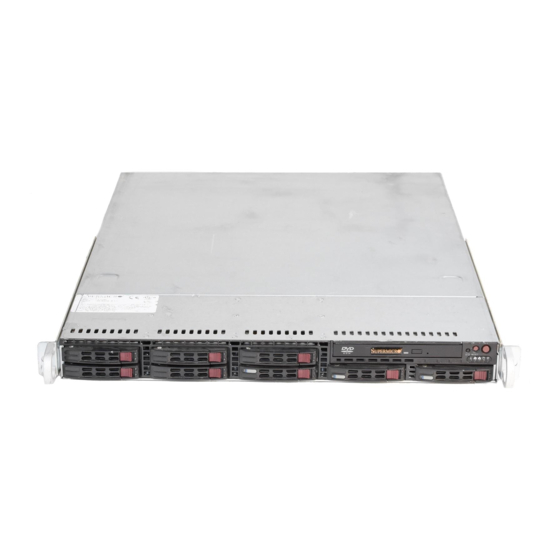
UPER ERVER 1026T-URF/1026T-UF Manual Figure 6-1. Chassis: Front and Rear Views DVD-ROM Drive Control Panel Hot-Swap Drive Bays (8) Power Supplies Mouse/Kybrd Dedicated IPMI LAN VGA Port PCI Slots USB Ports COM Port LAN Ports UID Button Note: the 1026T-UF features a single power supply only. -
Page 79: System Fan Failure
Chapter 6: Advanced Chassis Setup Adding a System Fan 1. Turn off the power to the system and unplug the power cord. 2. Remove the chassis cover then remove the dummy fan from the fan tray. 3. Place the new fan into the vacant space in the housing while making sure the arrows on the top of the fan (indicating air direction) point in the same direc- tion as the arrows on the other fans. -
Page 80: Drive Bay Installation/Removal
Proceed to the "DVD-ROM Drive Installation" section later in this chapter for instructions. Note: Only a "slim" DVD-ROM drive will fi t into the 1026T-URF/1026T-UF. Hard Drive Installation The hard drives are mounted in drive carriers to simplify their installation and removal from the chassis. - Page 81 Chapter 6: Advanced Chassis Setup 2. Align the drive in the carrier so that the screw holes of both line up. Note that there are holes in the carrier marked “SATA” to aid in correct installation. 3. Secure the drive to the carrier with four screws as illustrated below. 4.
-
Page 82: Dvd Drive Installation
UPER ERVER 1026T-URF/1026T-UF Manual Figure 6-4. Removing a Hard Drive DVD Drive Installation The SC113 chassis includes a pre-installed DVD-ROM. Installing or Replacing a DVD-ROM Drive (Figure 6-5) 1. Power down the system and if necessary, remove the server from the rack and the front bezel from the chassis. - Page 83 Chapter 6: Advanced Chassis Setup 5. Insert the new drive unit in the slot until the tab locks in place. 6. Reconnect the data and power cables. 7. Replace the chassis cover (replace the server in the rack, if necessary) and power up the system.
-
Page 84: Power Supply
Power Supply 1026T-URF The SuperServer 1026T-URF has a 650 watt redundant power supply, which is auto-switching capable. This enables it to automatically sense and operate with a 100V to 240V input voltage. A power on/off switch is included on the back of the unit. -
Page 85: 1026T-Uf
5. Push the new power supply module into the power bay until you hear a click. 6. Reconnect the AC power cord and depress the power button on the control panel to restart the system. Figure 6-6. Removing/Replacing the Power Supply Note: 1026T-URF shown - the 1026T-UF has a single (non-hot swappable) power supply module. - Page 86 UPER ERVER 1026T-URF/1026T-UF Manual Notes 6-10...
-
Page 87: Chapter 7 Bios
When an option is selected in the left frame, it is highlighted in white. Often a text message will accompany it. (Note: the AMI BIOS has default text messages built in. Supermicro retains the option to include, omit, or change any of these text messages.) The AMI BIOS Setup Utility uses a key-based navigation system called "hot keys". -
Page 88: Main Setup
Flashing the wrong BIOS can cause irreparable damage to the system. In no event shall Supermicro be liable for direct, indirect, special, incidental, or consequential dam- ages arising from a BIOS update. If you have to update the BIOS, do not shut down or reset the system while the BIOS is updating. - Page 89 Chapter 7: BIOS AMI BIOS • Version: This item displays the BIOS revision used in your system. • Build Date: This item displays the date when this BIOS was complete. Processor The AMI BIOS will automatically display the status of the processor used in your system: •...
-
Page 90: Advanced Setup Confi Gurations
UPER ERVER 1026T-URF/1026T-UF User's Manual Advanced Setup Confi gurations Use the arrow keys to select Boot Setup and hit <Enter> to access the submenu items: BOOT Features Quick Boot If Enabled, this option will skip certain tests during POST to reduce the time needed for system boot. -
Page 91: Processor And Clock Options
Chapter 7: BIOS Wait For 'F1' If Error This forces the system to wait until the 'F1' key is pressed if an error occurs. The options are Disabled and Enabled. Hit 'Del' Message Display This feature displays "Press DEL to run Setup" during POST. The options are Enabled and Disabled. - Page 92 UPER ERVER 1026T-URF/1026T-UF User's Manual Hardware Prefetcher (Available when supported by the CPU) If set to Enabled, the hardware pre fetcher will pre fetch streams of data and instruc- tions from the main memory to the L2 cache in the forward or backward manner to improve CPU performance.
-
Page 93: Advanced Chipset Control
Chapter 7: BIOS C1E Support Select Enabled to use the feature of Enhanced Halt State. C1E signifi cantly reduces the CPU's power consumption by reducing the CPU's clock cycle and voltage during a "Halt State." The options are Disabled and Enabled. Intel®... - Page 94 UPER ERVER 1026T-URF/1026T-UF User's Manual QPI Links Speed This feature selects QPI's data transfer speed. The options are Slow-mode, and Full Speed. QPI Frequency This selects the desired QPI frequency. The options are Auto, 4.800 GT, 5.866GT, 6.400 GT. QPI L0s and L1 This enables the QPI power state to low power.
- Page 95 Chapter 7: BIOS Hysteresis Temperature (This feature is available when Closed Loop is enabled.) Temperature Hysteresis is the temperature lag (in degrees Celsius) after the set DIMM temperature threshold is reached before Closed Loop Throttling begins. The options are Disabled, 1.5 o C, 3.0 C, and 6.0 Guardband Temperature (This feature is available when Closed Loop is enabled.)
- Page 96 UPER ERVER 1026T-URF/1026T-UF User's Manual providing the user with greater reliability, security and availability in networking and data-sharing. The options are Enabled and Disabled. SR-IOV Supported Select Enabled to enable Single Root I/O Virtualization (SR-IOV) support which works in conjunction with the Intel Virtualization Technology and allow multiple op- erating systems running simultaneously within a single computer via natively share PCI-Express devices in order to enhance network connectivity and performance.
- Page 97 Chapter 7: BIOS USB Functions This feature allows the user to decide the number of onboard USB ports to be en- abled. The Options are: Disabled, 2 USB ports, 4 USB ports, 6 USB ports, 8 Ports, 10 Ports and 12 USB ports. USB 2.0 Controller This item indicates if the onboard USB 2.0 controller is activated.
- Page 98 UPER ERVER 1026T-URF/1026T-UF User's Manual SATA AHCI (Available when the option-AHCI is selected.) Select Enable to enable the function of Serial ATA Advanced Host Interface. (Take caution when using this function. This feature is for advanced program- mers only.) IDE Detect Timeout (sec) Use this feature to set the time-out value for the BIOS to detect the ATA, ATAPI devices installed in the system.
- Page 99 Chapter 7: BIOS PCI-E Slot from SXB1/PCI-E Slot from SXB2/PCI-E Slot from SXB3 Select Enabled to enable PCI-E SXB1 slot, PCI-E SXB2 slot or PCI-E SXB3 slot. It can also enable Option ROMs to boot computer using a network interface from these slots.
-
Page 100: Hardware Health Monitor
UPER ERVER 1026T-URF/1026T-UF User's Manual Serial Port Mode This feature allows the user to set the serial port mode for Console Redirection. The options are 115200 8, n 1; 57600 8, n, 1; 38400 8, n, 1; 19200 8, n, 1; and 9600 8, n, 1. - Page 101 ‘Temperature Tolerance’ is, and not the other way around. This results in better CPU thermal management. Supermicro has leveraged this feature by assigning a temperature status to certain thermal conditions in the processor (Low, Medium and High). This makes it easier for the user to understand the CPU’s temperature status, rather than by just simply...
- Page 102 UPER ERVER 1026T-URF/1026T-UF User's Manual User intervention: No action is required. However, consider checking the CPU fans and the chassis ventilation for blockage. High – The processor is running hot. This is a ‘caution’ level since the CPU’s ‘Tem- perature Tolerance’ has been reached (or has been exceeded) and may activate an overheat alarm.
- Page 103 Chapter 7: BIOS High Performance Event Timer Select Enabled to activate the High Performance Event Timer (HPET) that produces periodic interrupts at a much higher frequency than a Real-time Clock (RTC) does in synchronizing multimedia streams, providing smooth playback and reducing the de- pendency on other timestamp calculation devices, such as an x86 RDTSC Instruc- tion embedded in the CPU.
- Page 104 UPER ERVER 1026T-URF/1026T-UF User's Manual Status of BMC Working The Baseboard Management Controller (BMC) manages the interface between system management software and platform hardware. This item displays the status of the current BMC controller. View BMC System Event Log This feature displays the BMC System Event Log (SEL).
- Page 105 Chapter 7: BIOS Set LAN Confi guration Set this feature to confi gure the IPMI LAN adapter with a network address as shown in the following graphics. Channel Number - Enter the channel number for the SET LAN Confi g com- mand.
- Page 106 UPER ERVER 1026T-URF/1026T-UF User's Manual SET PEF Confi guration PEF Support Select Enabled to enable the function of Platform Event Filter (PEF) which will interpret BMC events and perform actions based on pre-determined settings or 'traps' under IPMI 1.5 specifi cations. Powering the system down or sending an alert when a triggering event is detected.
-
Page 107: Security Settings
Chapter 7: BIOS BMC Watch Dog TimeOut [Min:Sec] This option appears if BMC Watch Dog Timer Action (above) is enabled. This is a timed delay in minutes or seconds, before a system power down or reset after an operating system failure is detected. The options are [5 Min], [1 Min], [30 Sec], and [10 Sec]. - Page 108 UPER ERVER 1026T-URF/1026T-UF User's Manual Supervisor Password This item indicates if a Supervisor password has been entered for the system. "Not Installed" means a Supervisor password has not been used. User Password This item indicates if a user password has been entered for the system. "Not In- stalled"...
-
Page 109: Boot Confi Guration
Chapter 7: BIOS Boot Confi guration Use this feature to confi gure boot settings. Boot Device Priority This feature allows the user to specify the sequence of priority for the Boot Device. The settings are 1st boot device, 2nd boot device, 3rd boot device, 4th boot device, 5th boot device and Disabled. -
Page 110: Exit Options
UPER ERVER 1026T-URF/1026T-UF User's Manual Exit Options Select the Exit tab from the Setup Utility screen to enter the Exit screen. Save Changes and Exit When you have completed the system confi guration changes, select this option to leave the BIOS Setup Utility and reboot the computer, so the new system con- fi... -
Page 111: Appendix A Bios Error Beep Codes
Appendix A: BIOS Error Beep Codes Appendix A BIOS Error Beep Codes During the POST (Power-On Self-Test) routines, which are performed each time the system is powered on, errors may occur. Non-fatal errors are those which, in most cases, allow the system to continue the boot-up process. - Page 112 UPER ERVER 1026T-URF/1026T-UF User's Manual Notes...
-
Page 113: Appendix B Installing Windows
South Bridge RAID Settings before you install the Windows OS and other software drivers. To confi gure RAID settings, please refer to RAID Confi guration User Guides posted on our web site at www.supermicro.com/support/manuals. B-1 Installing the Windows OS for a RAID System 1. - Page 114 OS Setup will automatically load all device fi les and then continue with the OS installation. 4. After the Windows OS Installation is complete, the system will automatically reboot. 5. Insert the Supermicro Setup CD that came with your serverboard into the CD drive during system boot, and the main screen will display.
-
Page 115: Appendix C System Specifi Cations
Appendix C: System Specifi cations Appendix C System Specifi cations Processors Single or dual Intel® 5500 Series processors in LGA1366 sockets Note: Please refer to our web site for a complete listing of supported processors. Chipset Intel IOH-36D/ICH10R chipset BIOS 32 Mb AMI®... - Page 116 UPER ERVER 1026T-URF/1026T-UF User's Manual Chassis 1026T-URF: SC113TQ-R650 (1U rackmount form factor) 1026T-UF: SC113TQ-560 (1U rackmount form factor) Dimensions (both): (WxHxD) 17.2 x 1.7 x 23.5 in. (437 x 43 x 597 mm) Weight Gross (Bare Bone): 33 lbs. (15 kg.)
- Page 117 Appendix C: System Specifi cations California Best Management Practices Regulations for Perchlorate Materials: This Perchlorate warning applies only to products containing CR (Manganese Dioxide) Lithium coin cells. “Perchlorate Material-special handling may apply. See www.dtsc.ca.gov/hazardouswaste/perchlorate”...
- Page 118 ERVER 1026T-URF/1026T-UF User's Manual (continued from front) The products sold by Supermicro are not intended for and will not be used in life support systems, medical equipment, nuclear facilities or systems, aircraft, aircraft devices, aircraft/emergency com- munication devices or other critical systems whose failure to perform be reasonably expected to result in signifi...
Need help?
Do you have a question about the SUPERSERVER 1026T-URF and is the answer not in the manual?
Questions and answers