Table of Contents
Advertisement
Quick Links
Advertisement
Table of Contents

Related Manuals for Supero SUPERSERVER 1028R-WMR


Summary of Contents for Supero SUPERSERVER 1028R-WMR
- Page 1 UPER ® UPER ERVER ® 1028R-WMR(T) USER’S MANUAL Revision 1.0...
- Page 2 The information in this User’s Manual has been carefully reviewed and is believed to be accurate. The vendor assumes no responsibility for any inaccuracies that may be contained in this document, makes no commitment to update or to keep current the information in this manual, or to notify any person or organization of the updates.
- Page 3 Preface Preface About this Manual This manual is written for professional system integrators and PC technicians. It provides information for the installation and use of the SuperServer. Installation and maintainance should be performed by experienced technicians only. Please refer to the server specifications page on our Web site for updates on supported memory, processors and operating systems (http://www.supermicro.
-
Page 4: Table Of Contents
UPER ERVER 1028R-WMR(T) Manual Contents Chapter 1 Introduction Overview ......................1-1 Serverboard Features ..................1-2 Processors ...................... 1-2 Memory ......................1-2 Serial ATA ......................1-2 PCI Expansion Slots ..................1-2 Input/Output Ports ..................1-2 IPMI ......................... 1-3 Server Chassis Features ................1-4 System Power .................... - Page 5 Preface Control Panel LEDs ..................3-2 Overheating ..................... 3-3 Overheat Temperature Setting ..............3-3 Responses ....................3-3 Drive Carrier LEDs ..................3-4 Power Supply LEDs ..................3-4 Chapter 4 Standardized Warning Statements for AC Systems About Standardized Warning Statements ............4-1 Warning Definition ...................
- Page 6 UPER ERVER 1028R-WMR(T) Manual Expansion Cards ................... 5-10 Serverboard Details ..................5-11 Connector Definitions ................... 5-14 Power Connectors ..................5-14 Jumper Settings .................... 5-20 5-10 Onboard Indicators ..................5-22 5-11 SATA ......................5-23 5-12 Installing Software ..................5-24 SuperDoctor 5 ..................... 5-25 ®...
- Page 7 Preface Contacting Supermicro Headquarters Address: Super Micro Computer, Inc. 980 Rock Ave. San Jose, CA 95131 U.S.A. Tel: +1 (408) 503-8000 Fax: +1 (408) 503-8008 Email: marketing@supermicro.com (General Information) support@supermicro.com (Technical Support) Web Site: www.supermicro.com Europe Address: Super Micro Computer B.V. Het Sterrenbeeld 28, 5215 ML 's-Hertogenbosch, The Netherlands Tel:...
- Page 8 UPER ERVER 1028R-WMR(T) Manual Notes...
-
Page 9: Chapter 1 Introduction
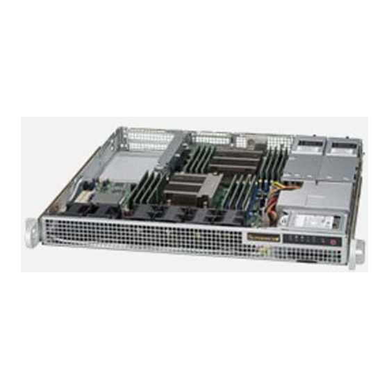
Chapter 1 Introduction Overview The SuperServer 1028R-WMR(T) is a 1U server comprised of two main subsystems: the SC514-R400W 1U server chassis and the X10DRW-E(T) serverboard. The 1028R-WMRT model, with the X10DRW-ET serverboard, offers 10 Gb Ethernet capabilities. Refer to our web site to learn which operating systems have been certified for use with this system (www.supermicro.com). -
Page 10: Serverboard Features
SUPERSERVER 1028R-WMR(T) User's Manual Serverboard Features At the heart of the 1028R-WMR(T) SuperServer is the X10DRW-E(T), a dual processor serverboard based on the Intel C612 Express chipset. Below are the main features of the system (See Figure 1-1 for a chipset block diagram). -
Page 11: Ipmi
Chapter 1: Introduction IPMI IPMI (Intelligent Platform Management Interface) is a hardware-level interface specification that provides remote access, monitoring and administration for Supermicro server platforms. IPMI allows server administrators to view a server’s hardware status remotely, receive an alarm automatically if a failure occurs, and power cycle a system that is non-responsive. -
Page 12: Server Chassis Features
SUPERSERVER 1028R-WMR(T) User's Manual Server Chassis Features The 1028R-WMR(T) is built upon the SC514-R400W chassis. The following are the main features of the chassis. System Power The SC514-R400W chassis features a redundant 400 W power supply consisting of two power modules. Either module can be removed and replaced without powering down the system. -
Page 13: Contacting Supermicro
Chapter 1: Introduction Contacting Supermicro Headquarters Address: Super Micro Computer, Inc. 980 Rock Ave. San Jose, CA 95131 U.S.A. Tel: +1 (408) 503-8000 Fax: +1 (408) 503-8008 Email: marketing@supermicro.com (General Information) support@supermicro.com (Technical Support) Web Site: www.supermicro.com Europe Address: Super Micro Computer B.V. Het Sterrenbeeld 28, 5215 ML 's-Hertogenbosch, The Netherlands Tel:... - Page 14 SUPERSERVER 1028R-WMR(T) User's Manual Notes...
-
Page 15: Chapter 2 Installation In A Rack
Chapter 2: Installation in a Rack Chapter 2 Installation in a Rack This chapter provides instructions for mounting your chassis in a rack. Preparing for Setup The box in which your system was shipped should include two sets of rail assemblies, two rail mounting brackets and the mounting screws to mount the system into the rack. -
Page 16: Warnings And Precautions
SUPERSERVER 1028R-WMR(T) User's Manual Warnings and Precautions Rack Precautions • Ensure that the leveling jacks on the bottom of the rack are fully extended to the floor with the full weight of the rack resting on them. • In single rack installation, stabilizers should be attached to the rack. In multiple rack installations, the racks should be coupled together. -
Page 17: Rack Mounting Considerations
Chapter 2 Installation in a Rack Rack Mounting Considerations Ambient Operating Temperature If installed in a closed or multi-unit rack assembly, the ambient operating temperature of the rack environment may be greater than the ambient temperature of the room. Therefore, consideration should be given to installing the equipment in an environment compatible with the manufacturer’s maximum rated ambient temperature (Tmra). -
Page 18: Installing The System Into A Rack
SUPERSERVER 1028R-WMR(T) User's Manual Installing the System into a Rack This section provides information on installing the chassis into a rack unit with the rails provided. There are a variety of rack units on the market, which may mean that the assembly procedure differs slightly. You should also refer to the installation instructions that came with the rack unit you are using. -
Page 19: Assembling The Outer Rails
Chapter 2 Installation in a Rack Assembling the Outer Rails Each outer rail comes in two sections that must be assembled before mounting onto the rack. Assembling the Outer Rails 1. Identify the left and right outer rails by examining the ends, which bend outward. Match the left front outer rail with the left rear outer rail and the same for the right rails. -
Page 20: Installing The Outer Rails Onto The Rack
SUPERSERVER 1028R-WMR(T) User's Manual Installing the Outer Rails onto the Rack Each end of the assembled outer rail includes a bracket with square pegs to fit into your rack holes. If you have an older rack with round holes, these brackets must be removed, and you must use screws to secure the rail to the rack. -
Page 21: Sliding The Chassis Onto The Rack Rails
Chapter 2 Installation in a Rack Sliding the Chassis onto the Rack Rails Installing the Chassis into a Rack 1. Align the chassis rails with the front of the rack rails. 2. Slide the chassis rails into the rack rails, keeping the pressure even on both sides. -
Page 22: Installing The Server Into A Two Post Rack
SUPERSERVER 1028R-WMR(T) User's Manual Installing the Server into a Two Post Rack Optional brackets (p/n MCP-290-00016-0N) are needed to install the server to a two post (telco type) rack. Use the two L-shaped brackets on either side of the chassis (four total). First, determine how far follow the server will extend out the front of the rack. -
Page 23: Chapter 3 System Interface
Chapter 3 System Interface Chapter 3 System Interface Overview The chassis includes: • A control panel on the front that includes power buttons and status monitoring lights • Status lights on externally accessible hard drives • Status lights for the power supply Figure 3-1. -
Page 24: Control Panel Buttons
SUPERSERVER 1018GR-T User's Manual Control Panel Buttons The chassis includes two push-buttons. Reset: The reset button is used to reboot the system. Power: The main power switch is used to apply or remove power from the power supply to the server. Turning off system power with this button removes the main power but maintains standby power. -
Page 25: Overheating
Chapter 3 System Interface NIC1: Indicates network activity on GLAN1 when flashing. HDD: Indicates IDE channel activity on the hard drive when flashing. Power: Indicates power is being supplied to the system power supply units. This LED should normally be illuminated when the system is operating. Overheating There are several possible responses if the system overheats. -
Page 26: Drive Carrier Leds
SUPERSERVER 1018GR-T User's Manual Drive Carrier LEDs The chassis includes externally accessible SAS/SATA drives. Each drive carrier displays two status LEDs on the front of the carrier. • Green: When illuminated, this LED indicates drive activity. It blinks on and off when that particular drive is being accessed This function is controlled by the backplane. -
Page 27: Chapter 4 Standardized Warning Statements For Ac Systems
Chapter 4: Warning Statements for AC Systems Chapter 4 Standardized Warning Statements for AC Systems About Standardized Warning Statements The following statements are industry standard warnings, provided to warn the user of situations which have the potential for bodily injury. Should you have questions or experience difficulty, contact Supermicro's Technical Support department for assistance. - Page 28 SUPERSERVER 1028R-WMR(T) User's Manual Warnung WICHTIGE SICHERHEITSHINWEISE Dieses Warnsymbol bedeutet Gefahr. Sie befinden sich in einer Situation, die zu Verletzungen führen kann. Machen Sie sich vor der Arbeit mit Geräten mit den Gefahren elektrischer Schaltungen und den üblichen Verfahren zur Vorbeugung vor Unfällen vertraut.
- Page 29 Chapter 4: Warning Statements for AC Systems جسذٌة اصابة ًتتسبب ف حالة ٌوكي أى ًاًك ف خطز ًٌٌع هذا الزهز !تحذٌز الذوائز بالوخاطز الٌاجوة عي ي على علن ، ك هعذات تعول على أي قبل أى الكهزبائٍة حىادث أي وقىع وٌع...
-
Page 30: Installation Instructions
SUPERSERVER 1028R-WMR(T) User's Manual Installation Instructions Warning! Read the installation instructions before connecting the system to the power source. 設置手順書 システムを電源に接続する前に、 設置手順書をお読み下さい。 警告 将此系统连接电源前,请先阅读安装说明。 警告 將系統與電源連接前,請先閱讀安裝說明。 Warnung Vor dem Anschließen des Systems an die Stromquelle die Installationsanweisungen lesen. ¡Advertencia! Lea las instrucciones de instalación antes de conectar el sistema a la red de alimentación. -
Page 31: Circuit Breaker
Chapter 4: Warning Statements for AC Systems Circuit Breaker Warning! This product relies on the building's installation for short-circuit (overcurrent) protection. Ensure that the protective device is rated not greater than: 250 V, 20 A. サーキッ ト ・ ブレーカー この製品は、 短絡 (過電流) 保護装置がある建物での設置を前提としています。 保護装置の定格が250 V、... -
Page 32: Power Disconnection Warning
SUPERSERVER 1028R-WMR(T) User's Manual 경고! 이 제품은 전원의 단락(과전류)방지에 대해서 전적으로 건물의 관련 설비에 의존합니다. 보호장치의 정격이 반드시 250V(볼트), 20A(암페어)를 초과하지 않도록 해야 합니다. Waarschuwing Dit product is afhankelijk van de kortsluitbeveiliging (overspanning) van uw electrische installatie. Controleer of het beveiligde aparaat niet groter gedimensioneerd is dan 220V, 20A. - Page 33 Chapter 4: Warning Statements for AC Systems ¡Advertencia! El sistema debe ser disconnected de todas las fuentes de energía y del cable eléctrico quitado de los módulos de fuente de alimentación antes de tener acceso el interior del chasis para instalar o para quitar componentes de sistema. Attention Le système doit être débranché...
-
Page 34: Equipment Installation
SUPERSERVER 1028R-WMR(T) User's Manual Equipment Installation Warning! Only trained and qualified personnel should be allowed to install, replace, or service this equipment. 機器の設置 トレーニングを受け認定された人だけがこの装置の設置、 交換、 またはサービスを許可 されています。 警告 只有经过培训且具有资格的人员才能进行此设备的安装、更换和维修。 警告 只有經過受訓且具資格人員才可安裝、更換與維修此設備。 Warnung Das Installieren, Ersetzen oder Bedienen dieser Ausrüstung sollte nur geschultem, qualifiziertem Personal gestattet werden. -
Page 35: Restricted Area
Chapter 4: Warning Statements for AC Systems Waarschuwing Deze apparatuur mag alleen worden geïnstalleerd, vervangen of hersteld door geschoold en gekwalificeerd personeel. Restricted Area Warning! This unit is intended for installation in restricted access areas. A restricted access area can be accessed only through the use of a special tool, lock and key, or other means of security. -
Page 36: Battery Handling
SUPERSERVER 1028R-WMR(T) User's Manual אזור עם גישה מוגבלת !אזהרה יש להתקין את היחידה באזורים שיש בהם הגבלת גישה. הגישה ניתנת בעזרת .)'כלי אבטחה בלבד (מפתח, מנעול וכד محظورة مناطق ٍنتركُبها ف هذه انىحذة تخصيص تم ،أداة خاصت من خالل استخذاو... - Page 37 Chapter 4: Warning Statements for AC Systems Warnung Bei Einsetzen einer falschen Batterie besteht Explosionsgefahr. Ersetzen Sie die Batterie nur durch den gleichen oder vom Hersteller empfohlenen Batterietyp. Entsorgen Sie die benutzten Batterien nach den Anweisungen des Herstellers. Attention Danger d'explosion si la pile n'est pas remplacée correctement. Ne la remplacer que par une pile de type semblable ou équivalent, recommandée par le fabricant.
-
Page 38: Redundant Power Supplies (If Applicable To Your System)
SUPERSERVER 1028R-WMR(T) User's Manual Redundant Power Supplies (if applicable to your system) Warning! This unit might have more than one power supply connection. All connections must be removed to de-energize the unit. 冗長電源装置 このユニッ トは複数の電源装置が接続されている場合があります。 ユニッ トの電源を切るためには、 すべての接続を取り外さなければなりません。 警告 此部件连接的电源可能不止一个,必须将所有电源断开才能停止给该部件供电。... -
Page 39: Backplane Voltage (If Applicable To Your System)
Chapter 4: Warning Statements for AC Systems امداد الطاقة بوحدات عدة اتصاالت جهاز ال يكون لهذا قد الكهرباء عن وحدة ال لعسل كافة االتصاالت يجب إزالة 경고! 이 장치에는 한 개 이상의 전원 공급 단자가 연결되어 있을 수 있습니다. 이 장치에... -
Page 40: Comply With Local And National Electrical Codes
SUPERSERVER 1028R-WMR(T) User's Manual מתח בפנל האחורי !הרה אז קיימת סכנת מתח בפנל האחורי בזמן תפעול המערכת. יש להיזהר במהלך .העבודה اللىحة أوالطاقة المىجىدة على التيار الكهزبائي مه خطز هناك هذا الجهاس خدمة كه حذرا عند يعمل النظام عندما يكىن... -
Page 41: Product Disposal
Chapter 4: Warning Statements for AC Systems Attention L'équipement doit être installé conformément aux normes électriques nationales et locales. תיאום חוקי החשמל הארצי !אזהרה הציוד חייבת להיות תואמת לחוקי החשמל המקומיים והארציים התקנת المتعلقة المحلية والىطىية قىاويه يجب أن يمتثل لل الكهربائية... -
Page 42: Hot Swap Fan Warning (If Applicable To Your System)
SUPERSERVER 1028R-WMR(T) User's Manual ¡Advertencia! Al deshacerse por completo de este producto debe seguir todas las leyes y reglamentos nacionales. Attention La mise au rebut ou le recyclage de ce produit sont généralement soumis à des lois et/ou directives de respect de l'environnement. Renseignez-vous auprès de l'organisme compétent. - Page 43 Chapter 4: Warning Statements for AC Systems 警告 當您從機架移除風扇裝置,風扇可能仍在轉動。小心不要將手指、螺絲起子和其他 物品太靠近風扇。 Warnung Die Lüfter drehen sich u. U. noch, wenn die Lüfterbaugruppe aus dem Chassis genommen wird. Halten Sie Finger, Schraubendreher und andere Gegenstände von den Öffnungen des Lüftergehäuses entfernt. ¡Advertencia! Los ventiladores podran dar vuelta cuando usted quite ell montaje del ventilador del chasis.
-
Page 44: Power Cable And Ac Adapter
SUPERSERVER 1028R-WMR(T) User's Manual Power Cable and AC Adapter Warning! When installing the product, use the provided or designated connection cables, power cables and AC adaptors. Using any other cables and adaptors could cause a malfunction or a fire. Electrical Appliance and Material Safety Law prohibits the use of UL or CSA -certified cables (that have UL/CSA shown on the code) for any other electrical devices than products designated by Supermicro only. - Page 45 Chapter 4: Warning Statements for AC Systems Attention Lors de l'installation du produit, utilisez les bables de connection fournis ou désigné. L'utilisation d'autres cables et adaptateurs peut provoquer un dysfonctionnement ou un incendie. Appareils électroménagers et de loi sur la sécurité Matériel interdit l'utilisation de UL ou CSA câbles certifiés qui ont UL ou CSA indiqué...
- Page 46 SUPERSERVER 1028R-WMR(T) User's Manual Notes 4-20...
-
Page 47: Chapter 5 Advanced Serverboard Setup
Chapter 5: Advanced Motherboard Setup Chapter 5 Advanced Serverboard Setup This chapter covers the steps required to connect the data and power cables and install add-on cards. All serverboard jumpers and connections are also described. A layout and quick reference chart are included in this chapter for your reference. Note: Remember to completely close the chassis when you have finished working with the serverboard to better cool and protect the system. -
Page 48: Connecting Cables
SUPERSERVER 1028R-WMR(T) User's Manual Connecting Cables Once the serverboard is installed, the cables must be connected. These include the data cables for the peripherals and control panel, and the power cables. Connecting Data Cables The ribbon cables used to transfer data have been carefully routed to prevent them from blocking the flow of cooling air that moves through the system from front to back. -
Page 49: I/O Ports
Chapter 5: Advanced Motherboard Setup I/O Ports Figure 5-1. Rear I/O Ports 1. Back Panel VGA (Blue) 2. Back Panel USB 2.0 Port 0 3. Back Panel USB 2.0 Port 1 4. IPMI_Dedicated LAN 5. Back Panel USB 2.0 Port 2 6. -
Page 50: Installing The Processor And Heatsink
SUPERSERVER 1028R-WMR(T) User's Manual Installing the Processor and Heatsink Notes: • Always remove the power cord before adding, removing or changing a CPU. • When receiving a serverboard without a processor pre-installed, make sure that the plastic CPU socket cap is in place and none of the socket pins are bent;... - Page 51 Chapter 5: Advanced Motherboard Setup 3. With the second lever fully Open the load plate. retracted, gently push down on the "Open 1st" lever to loosen the load plate. Lift the load plate with your fingers to open it completely. 4.
- Page 52 SUPERSERVER 1028R-WMR(T) User's Manual Gently close the load plate. 7. With the "Close 1st" lever fully retracted, gently close the load plate. Push down and lock the lever labeled "Close 1st". 8. Make sure the locking mechanism on the "Close 1st" lever catches the lip of the load plate.
-
Page 53: Installing The Cpu Heatsink
Chapter 5: Advanced Motherboard Setup Installing a CPU Heatsink 1. Place the heatsink on top of the CPU so that the four mounting holes are aligned with those on the retention mechanism. 2. Screw in two diagonal screws (the #1 and the #2 screws) until just snug. Do not over-tighten the screws, which could damage the CPU. -
Page 54: Installing Memory
SUPERSERVER 1028R-WMR(T) User's Manual Installing Memory Caution: Exercise extreme care when installing or removing DIMM modules to prevent damage. Note: Check the Supermicro website for recommended memory modules. Modules of the same size and speed are recommended. DIMM Installation LAN2... -
Page 55: Memory Support
Chapter 5: Advanced Motherboard Setup Memory Support The serverboard supports up to 1024 GB of Load Reduced (LRDIMM), and up to 512 GB of Registered (RDIMM) DDR4 (288-pin) ECC 2133/1866/1600 MHz memory in 16 slots (2 DIMMs per channel). DIMM sizes are 2GB, 4GB, 8GB, 16GB, 32GB, 64GB. -
Page 56: Expansion Cards
SUPERSERVER 1028R-WMR(T) User's Manual DDR4 RDIMM/ LRDIMM ECC Memory Module Support for E5-2600 (V3) Processors Speed (MT/s) Voltage (V) ... -
Page 57: Serverboard Details
Chapter 5: Advanced Motherboard Setup Serverboard Details LAN2 LAN1 USB2/3 USB0/1 UID-SW LAN CTRL IPMI_LAN X10DRW-E/T/N/NT Rev. 1.01 CPU2 P1_NVME1 BAR CODE BIOS LICENSE P1_NVME0 JI2C1 BIOS CPU1 JVRM2 JBT1 JVR1 LED2 Notes: • " " indicates the location of "Pin 1". •... - Page 58 SUPERSERVER 1028R-WMR(T) User's Manual Connectors Connectors Description Battery (JBAT1) Onboard CMOS battery COM1 COM header Fan1-4, A, B System cooling fan headers Front Panel Control header JIPMB1 4-pin External BMC I C header Chassis Intrusion header Power Supply SMBbus I...
- Page 59 Chapter 5: Advanced Motherboard Setup Jumpers Jumper Description Default Setting JBT1 Clear CMOS See Chapter 2 C1/JI C2 SMB to PCI-E Slots Pins 2-3 (Disabled) JPB1 BMC Enable Pins 1-2 (Enabled) JPG1 VGA Enable Pins 1-2 (Enabled) JPL1 GLAN1/GLAN2 Enable (for X10DRW-E) Pins 1-2 (Enabled) 10G-LAN1/ 10G-LAN1 Enable (for X10DRW- JPME2...
-
Page 60: Connector Definitions
SUPERSERVER 1028R-WMR(T) User's Manual Connector Definitions Power Connectors A 24-pin main power supply con- ATX Power 24-pin Connector nector (JPWR1), and two 8-pin CPU Pin Definitions power connectors (JPWR2/JPWR3) Pin# Definition Pin # Definition are located on the serverboard. +3.3V +3.3V... - Page 61 Chapter 5: Advanced Motherboard Setup Control Panel Connectors Ground x (Key) x (Key) Power On LED 3.3 V HDD LED UID switch NIC1 LED (Link) NIC1 LED (Activity) NIC2 LED (Link) NIC2 LED (Activity) OH/Fan Fail/Pwr Fail LED UID LED Power Fail LED 3.3 V Ground...
- Page 62 SUPERSERVER 1028R-WMR(T) User's Manual Info LED (Front Panel) OH/Fan Fail/ PWR Fail/Blue_UID LED Pin Definitions (JF1) Connect a cable to pins 7 and 8 of JF1 Pin# Definition to use the Info LED. The red LED on Blue_UID LED pin 8 provides warnings of overheat, OH/Fan Fail/Power Fail fan failure or power failure.
- Page 63 Chapter 5: Advanced Motherboard Setup Other Connectors Universal Serial Bus (USB) Front Panel USB (3.0) 4/5 Pin Definitions Four USB 2.0 ports (USB 0/1, 2/3) Pin # Definition Pin # Definition are located on the I/O back panel. In addition, an internal USB header that USB_PN2 USB_PN3 provides two USB 3.0 connections...
- Page 64 SUPERSERVER 1028R-WMR(T) User's Manual Fan Headers This serverboard has six system fan Fan Header Pin Definitions headers (Fan 1-Fan 4, Fan A & Fan Pin# Definition B). All these 4-pin fans headers are Ground (Black) backward compatible with the tradi- +12V (Red) tional 3-pin fans.
- Page 65 Chapter 5: Advanced Motherboard Setup Power SMB (I C) Connector PWR SMB Pin Definitions Power System Management Bus (I Pin# Definition connector (JPI C1) monitors power Clock supply, fan and system temperatures. Data See the table on the right for pin PMBUS_Alert definitions.
-
Page 66: Jumper Settings
SUPERSERVER 1028R-WMR(T) User's Manual Jumper Settings Explanation of Jumpers To modify the operation of the serverboard, jumpers can be used Connector to choose between optional settings. Pins Jumpers create shorts between two pins to change the function of the connector. Pin 1 is identified with... - Page 67 Chapter 5: Advanced Motherboard Setup LAN Port Enable/Disable (JPL1) LAN Enable Jumper Settings Jumper JPL1 enables or disables Setting Definition LAN Ports 1 and 2. See the table Pins 1-2 Enabled (Default) on the right for jumper settings. The Pins 2-3 Disabled default setting is enabled.
-
Page 68: 5-10 Onboard Indicators
SUPERSERVER 1028R-WMR(T) User's Manual 5-10 Onboard Indicators LAN 1/2 LEDs Two LAN ports (LAN 1/LAN 2) are located on the IO back panel of the serverboard. Each Ethernet LAN port has two LEDs. The green LED indicates activity, while the other Link LED may be green, amber or off to indicate the speed of the connec- tions. -
Page 69: 5-11 Sata
Chapter 5: Advanced Motherboard Setup 5-11 SATA SATA 3.0 Connections This server supports two fixed hard drives. Nevertheless, the serverboard pro- vides ten SATA connections. I-SATA0-5 are supported by Intel PCH. S-SATA connections 0-3 are supported by Intel SCU. I-SATA4/5 are used with Supermicro SuperDOM (Disk-on-Module) connectors, which are yellow SATADOM connectors with power pins built-in and do not require separate external power cables. -
Page 70: 5-12 Installing Software
SUPERSERVER 1028R-WMR(T) User's Manual 5-12 Installing Software The Supermicro ftp site contains drivers and utilities for your system at ftp://ftp. supermicro.com. Some of these must be installed, such as the chipset driver. After accessing the ftp site, go into the CDR_Images directory and locate the ISO file for your serverboard. -
Page 71: Superdoctor ® 5
Chapter 5: Advanced Motherboard Setup SuperDoctor ® The Supermicro SuperDoctor 5 is a hardware and operating system services ® monitoring program that functions in a command-line or web-based interface in Windows and Linux operating systems. The program monitors system health information such as CPU temperature, system voltages, system power consumption, fan speed, and provides alerts via email or Simple Network Management Protocol (SNMP). -
Page 72: 5-13 Serverboard Battery
SUPERSERVER 1028R-WMR(T) User's Manual Figure 5-8. SuperDoctor 5 Interface Display Screen (Remote Control) Note: The SuperDoctor 5 program and User’s Manual can be downloaded from the Supermicro web site at http://www.supermicro.com/products/nfo/sms_sd5.cfm. For Linux, we recommend that you use the SuperDoctor II application instead. -
Page 73: Chapter 6 Advanced Chassis Setup
Chapter 6: Advanced Chassis Setup Chapter 6 Advanced Chassis Setup This chapter covers the steps required to install components and perform maintenance on the chassis. The only tool required is a Phillips screwdriver. Review the warnings and precautions listed in the manual before setting up or servicing this chassis. -
Page 74: Removing Power From The System
SUPERSERVER 1028R-WMR(T)F Series User's Manual • Put the serverboard, add-on cards and peripherals back into their antistatic bags when not in use. • For grounding purposes, make sure your computer chassis provides excellent conductivity between the power supply, the case, the mounting fasteners and the serverboard. -
Page 75: Removing The Chassis Cover
Chapter 6: Advanced Chassis Setup Removing the Chassis Cover You may need to remove the top cover to access the inside of the system for some of the procedures desccibed in this chapter. Removing the Chassis Cover: 1. Remove the thumb screw securing the top cover to the chassis. 2. -
Page 76: Installing Hard Drives
SUPERSERVER 1028R-WMR(T)F Series User's Manual Installing Hard Drives The server supports two fixed 2.5" hard disk drives. Only SAS or SATA enterprise level hard drives are recommended. Installing Hard Disk Drives 1. Identify the HDD bracket and secure the drive(s) to the bracket. (Figure 6-3) - Page 77 Chapter 6: Advanced Chassis Setup Figure 6-5. Securing the HDD Tray to the Chassis Floor...
-
Page 78: System Fans
SUPERSERVER 1028R-WMR(T)F Series User's Manual System Fans The SC514 chassis includes four heavy-duty fans and connecdtors for two optional fans to provide cooling. Replacing a System Fan 1. If necessary, open the chassis cover while the power is running to determine which fan requires changing. - Page 79 Chapter 6: Advanced Chassis Setup Figure 6-6. Fan Layout Figure 6-7. Removing a Fan from the Fan Housing...
-
Page 80: Installing Expansion Cards
SUPERSERVER 1028R-WMR(T)F Series User's Manual Installing Expansion Cards The system supports two full-height, half length PCI Express expansion cards. They are installed using a riser card and riser bracket. Screwdriver Icon Securing Latch Install Riser Card Riser Card Bracket Figure 6-7. Removing the Riser Bracket Installing Expansion Cards 1. - Page 81 Chapter 6: Advanced Chassis Setup Figure 6-8. Rear Expansion Slots 6. Install the entire assembly into the appropriate slot on the serverboard while aligning the bracket in the rear of the chassis.
-
Page 82: Power Supply
SUPERSERVER 1028R-WMR(T)F Series User's Manual Power Supply The chassis has two hot-swap 400W power supplies They have an auto-switching capability, which enables them to automatically sense and operate at a 100V-240V input voltage. If a power supply unit fails, it can be changed without powering down the system. -
Page 83: Chapter 7 Bios
Chapter 7: AMI BIOS Chapter 7 BIOS Introduction This chapter describes the AMI BIOS setup utility for the X10DRW-E(T). The ROM BIOS is stored in a Flash EEPROM and can be easily updated. This chapter de- scribes the basic navigation of the AMI BIOS setup utility screens. Note: For AMI BIOS recovery, please refer to the UEFI BIOS Recovery Instructions in Appendix C. -
Page 84: Main Setup
SuperServer 1028R-WMR(T) User’s Manual How to Start the Setup Utility Normally, the only visible Power-On Self-Test (POST) routine is the memory test. As the memory is being tested, press the <Delete> key to enter the main menu of the AMI BIOS setup utility. From the main menu, you can access the other setup screens. - Page 85 Chapter 7: AMI BIOS <Tab> key or the arrow keys to move between fields. The date must be entered in Day MM/DD/YYYY format. The time is entered in HH:MM:SS format. Note: The time is in the 24-hour format. For example, 5:30 P.M. appears as 17:30:00.
-
Page 86: Advanced Setup Configurations
SuperServer 1028R-WMR(T) User’s Manual Advanced Setup Configurations Use the arrow keys to select Advanced setup and press <Enter> to access the submenu items: Warning: Take Caution when changing the Advanced settings. An incorrect value, an incorrect DRAM frequency, or an incorrect timing setting may cause the system to malfunction. - Page 87 Chapter 7: AMI BIOS Wait For 'F1' If Error Select Enabled to force the system to wait until the 'F1' key is pressed if an error occurs. The options are Disabled and Enabled. INT19 (Interrupt 19) Trap Response Interrupt 19 is the software interrupt that handles the boot disk function. When this item is set to Immediate, the ROM BIOS of the host adaptors will "capture"...
- Page 88 SuperServer 1028R-WMR(T) User’s Manual CPU Configuration This submenu displays the information of the CPU as detected by the BIOS. It also allows the user to configuration CPU settings. CPU Information This submenu displays the following information regarding the CPU installed in Socket 1 and (or) Socket 2 as detected by the BIOS.
- Page 89 Chapter 7: AMI BIOS Execute Disable Bit (Available if supported by the OS & the CPU) Select Enable to enable the Execute-Disable Bit technology which will allow the processor to designate areas in the system memory where an application code can execute and where it cannot, thus preventing a worm or a virus from flooding illegal codes to overwhelm the processor or damage the system during an attack.
- Page 90 SuperServer 1028R-WMR(T) User’s Manual Intel Virtualization Technology (Available when supported by the CPU) Select Enable to support Intel Virtualization Technology, which will allow one platform to run multiple operating systems and applications in independent parti- tions, creating multiple "virtual" systems in one physical computer. The options are Enable and Disable.
- Page 91 Chapter 7: AMI BIOS CPU C State Control Package C State limit This feature allows the user to set the limit on the C-State package register. The options are C0/C1 State, C2 State, C6 (Non Retention) State, and C6 (Reten- tion) State.
- Page 92 SuperServer 1028R-WMR(T) User’s Manual IIO Configuration EV DFX (Device Function On-Hide) Features When this feature is set to Enable, the EV_DFX Lock bits that are located on a processor will always remain clear during electric tuning. The options are Dis- able and Enable.
- Page 93 Chapter 7: AMI BIOS No Snoop Select Enable to support no-snoop mode to ensure cache coherency within each memory platform. The options are Disable and Enable. Relaxed Ordering Select Enable to enable Relaxed Ordering support which will allow certain trans- actions to violate the strict-ordering rules of PCI and to be completed prior to other transactions that have already been enqueued.
- Page 94 SuperServer 1028R-WMR(T) User’s Manual • QPI Global MMIO High Base / Limit • QPI PCI-E Configuration Base / Size Link Frequency Select Use this feature to select the desired QPI link frequency. The options are 6.4 GT/s, 8.0 GT/s, 9.6 GT/s, Auto, and Auto Limited.
- Page 95 Chapter 7: AMI BIOS Data Scrambling Select Enabled to enable data scrambling to enhance system performance and data integrity. The options are Auto, Disabled and Enabled. DRAM RAPL (Running Average Power Limit) Baseline Use this feature to set the run-time power-limit baseline for DRAM modules. The options are Disable, DRAM RAPL Mode 0, and DRAM RAPL Mode 1.
- Page 96 SuperServer 1028R-WMR(T) User’s Manual Memory RAS (Reliability_Availability_Serviceability) Configuration Use this submenu to configure the following Memory RAS settings. Memory RAS Configuration Setup RAS Mode When Disable is selected, RAS is not supported. When Mirror is selected, the motherboard maintains two identical copies of all data in memory for data backup.
- Page 97 Chapter 7: AMI BIOS South Bridge Configuration The following South Bridge information will display: USB Configuration • USB Module Version • USB Devices Legacy USB Support Select Enabled to support onboard legacy USB devices. Select Auto to disable legacy support if there are no legacy USB devices present.
- Page 98 SuperServer 1028R-WMR(T) User’s Manual EHCI2 Select Enabled to enable EHCI (Enhanced Host Controller Interface) support on USB 2.0 connector #2 (-at least one USB 2.0 connector should be enabled for EHCI support.) The options are Disabled and Enabled. XHCI Pre-Boot Driver Select Enabled to load the Intel XHCI (Extensible Host Controller Interface) pre-boot driver for system boot.
- Page 99 Chapter 7: AMI BIOS SATA Configuration When this submenu is selected, AMI BIOS automatically detects the presence of the SATA devices that are supported by the Intel PCH chip and displays the fol- lowing items: SATA Controller This item enables or disables the onboard SATA controller supported by the Intel PCH chip.
- Page 100 SuperServer 1028R-WMR(T) User’s Manual Port 0 ~ Port 5 Spin Up Device On an edge detect from 0 to 1, set this item to allow the PCH to initialize the device. The options are Enabled and Disabled. Port 0 ~ Port 5 SATA Device Type Use this item to specify if the SATA port specified by the user should be con- nected to a Solid State drive or a Hard Disk Drive.
- Page 101 Chapter 7: AMI BIOS Serial ATA Port 0~ Port 5 This item displays the information detected on the installed SATA drives on the particular SATA port. • Model number of drive and capacity • Software Preserve Support Port 0~ Port 5 Select Enabled to enable a SATA port specified by the user.
- Page 102 SuperServer 1028R-WMR(T) User’s Manual *If the item above "Configure sSATA as" is set to AHCI, the following items will display: Support Aggressive Link Power Management When this item is set to Enabled, the SATA AHCI controller manages the power usage of the SATA link. The controller will put the link to a low power state when the I/O is inactive for an extended period of time, and the power state will return to normal when the I/O becomes active.
- Page 103 Chapter 7: AMI BIOS Port 0 ~ Port 3 sSATA Device Type (Available when a SATA port is detected) Use this item to specify if the sSATA port specified by the user should be con- nected to a Solid State drive or a Hard Disk Drive. The options are Hard Disk Drive and Solid State Drive.
- Page 104 SuperServer 1028R-WMR(T) User’s Manual sSATA Port 0 ~ Port 3 Spin Up Device On an edge detect from 0 to 1, set this item to allow the PCH to start a COMRE- SET initialization to the device. The options are Enabled and Disabled.
- Page 105 Chapter 7: AMI BIOS Maximum Payload Select Auto for the system BIOS to automatically set the maximum payload value for a PCI-E device to enhance system performance. The options are Auto, 128 Bytes, and 256 Bytes. Maximum Read Request Select Auto for the system BIOS to automatically set the maximum size for a read request for a PCI-E device to enhance system performance.
- Page 106 SuperServer 1028R-WMR(T) User’s Manual a legacy video device installed on the motherboard. The options are Disabled, Legacy and EFI. VGA Priority Use this item to select the graphics device to be used as the primary video display for system boot. The options are Onboard and Offboard.
- Page 107 Chapter 7: AMI BIOS Serial Port Console Redirection COM 1 Console Redirection COM1 Console Redirection Select Enabled to enable COM Port 1 for Console Redirection, which will allow a client machine to be connected to a host machine at a remote site for networking. The options are Enabled and Disabled.
- Page 108 SuperServer 1028R-WMR(T) User’s Manual Stop Bits A stop bit indicates the end of a serial data packet. Select 1 Stop Bit for standard serial data communication. Select 2 Stop Bits if slower devices are used. The options are 1 and 2.
- Page 109 Chapter 7: AMI BIOS Console Redirection Select Enabled to use the SOL port for Console Redirection. The options are Enabled and Disabled. *If the item above set to Enabled, the following items will become available for user's configuration: SOL Console Redirection Settings Use this feature to specify how the host computer will exchange data with the client computer, which is the remote computer used by the user.
- Page 110 SuperServer 1028R-WMR(T) User’s Manual Stop Bits A stop bit indicates the end of a serial data packet. Select 1 Stop Bit for standard serial data communication. Select 2 Stop Bits if slower devices are used. The options are 1 and 2.
- Page 111 Chapter 7: AMI BIOS EMS Console Redirection Settings (Available when EMS Console Redirection is enabled) Use this feature to specify how the host computer will exchange data with the client computer, which is the remote computer used by the user. Out-of-Band Management Port The feature selects a serial port in a client server to be used by the Windows Emergency Management Services (EMS) to communicate with a remote host...
- Page 112 SuperServer 1028R-WMR(T) User’s Manual High Precision Timer Select Enabled to activate the High Precision Event Timer (HPET) that produces periodic interrupts at a much higher frequency than a Real-time Clock (RTC) does in synchronizing multimedia streams, providing smooth playback and reducing the de- pendency on other timestamp calculation devices, such as an x86 RDTSC Instruc- tion embedded in the CPU.
- Page 113 Chapter 7: AMI BIOS TXT Support Select Enabled to enable TXT (Trusted Execution Technology) settings to improve data and network security. The options are Disabled and Enabled. 7-31...
-
Page 114: Event Logs
SuperServer 1028R-WMR(T) User’s Manual Event Logs Use this feature to configure Event Log settings. Change SMBIOS Event Log Settings This feature allows the user to configure SMBIOS Event settings. Enabling/Disabling Options SMBIOS Event Log Select Enabled to enable SMBIOS (System Management BIOS) Event Logging during system boot. - Page 115 Chapter 7: AMI BIOS When Log is Full Select Erase Immediately to immediately erase all errors in the SMBIOS event log when the event log is full. Select Do Nothing for the system to do nothing when the SMBIOS event log is full. The options are Do Nothing and Erase Immediately. SMBIOS Event Log Standard Settings Log System Boot Event Select Enabled to log system boot events.
-
Page 116: Ipmi
SuperServer 1028R-WMR(T) User’s Manual IPMI Use this feature to configure Intelligent Platform Management Interface (IPMI) settings. IPMI Firmware Revision This item indicates the IPMI firmware revision used in your system. IPMI Status This item indicates the status of the IPMI firmware installed in your system. - Page 117 Chapter 7: AMI BIOS When SEL is Full This feature allows the user to determine what the BIOS should do when the sys- tem event log is full. Select Erase Immediately to erase all events in the log when the system event log is full. The options are Do Nothing and Erase Immediately. Note: Reboot the system for the changes to take effect.
-
Page 118: Security Settings
SuperServer 1028R-WMR(T) User’s Manual Security Settings This menu allows the user to configure the following security settings for the system. Password Check If this feature is set to Setup, a password is required for a user to enter the BIOS Setup utility. -
Page 119: Boot Settings
Chapter 7: AMI BIOS Boot Settings Use this feature to configure Boot Settings: Setup Prompt Timeout This feature allows the user to determine how long the system should wait for the setup activation key before it boots up. The default setting is 1 (second). Boot Mode Select Use this item to select the type of device to be used for system boot. - Page 120 SuperServer 1028R-WMR(T) User’s Manual • Boot Order #8 • Boot Order #9 • Boot Order #10 • Boot Order #11 • Boot Order #12 • Boot Order #13 • Boot Order #14 • Boot Order #15 Delete Boot Option Use this item to select a boot device to delete from the boot priority list.
-
Page 121: Save & Exit
Chapter 7: AMI BIOS Save & Exit Select the Save & Exit tab from the BIOS setup screen to configure the settings below. Discard Changes and Exit Select this option to quit the BIOS setup without making any permanent changes to the system configuration, and reboot the computer. - Page 122 SuperServer 1028R-WMR(T) User’s Manual Save As User Defaults To set this feature, select Save as User Defaults from the Exit menu and press <En- ter>. This enables the user to save any changes to the BIOS setup for future use.
-
Page 123: Appendix A Bios Post Error Codes
Appendix A: BIOS POST Error Codes Appendix A BIOS POST Error Codes During the POST (Power-On Self-Test) routines, which are performed each time the system is powered on, errors may occur. Non-fatal errors are those which, in most cases, allow the system to continue the boot-up process. - Page 124 UPER ERVER 1028R-WMR(T) User's Manual Notes...
-
Page 125: Appendix B System Specifications
Appendix B: System Specifications Appendix B System Specifications Processors Dual Intel E5-2600 (V3) processors Note: Refer to the Supermicro web site for a complete listing of supported processors. Chipset Intel C612 Express BIOS 128Mb SPI Flash EEPROM with AMI BIOS Memory Capacity: Up to 1TB ECC LRDIMM or 512GB ECC RDIMM in 16 288-pin DDR4 DIMM slots... - Page 126 SUPERSERVER 1028R-WMR(T) User's Manual Chassis SC514-R400W (1U rackmount) Dimensions: (WxHxD) 17.2 x 1.7 x 16.9 in. (437 x 43 x 429 mm) Gross weight: 27 lbs (12.25 kg) System Cooling Four sets of 4-cm counter-rotating cooling fans with an option for two more (fan...
- Page 127 Appendix B: System Specifications (continued from front) The products sold by Supermicro are not intended for and will not be used in life support systems, medical equipment, nuclear facilities or systems, aircraft, aircraft devices, aircraft/emergency com- munication devices or other critical systems whose failure to perform be reasonably expected to result in significant injury or loss of life or catastrophic property damage.
- Page 128 SUPERSERVER 1028R-WMR(T) User's Manual Notes...
Need help?
Do you have a question about the SUPERSERVER 1028R-WMR and is the answer not in the manual?
Questions and answers