Table of Contents
Advertisement
Quick Links
Advertisement
Table of Contents

Related Manuals for Supero SUPERSERVER 1026GT-TRF


Summary of Contents for Supero SUPERSERVER 1026GT-TRF
- Page 1 UPER ® UPER ERVER 1026GT-TRF USER’S MANUAL Revision 1.0...
- Page 2 The information in this User’s Manual has been carefully reviewed and is believed to be accurate. The vendor assumes no responsibility for any inaccuracies that may be contained in this document, makes no commitment to update or to keep current the information in this manual, or to notify any person or organization of the updates.
- Page 3 About This Manual This manual is written for professional system integrators and PC technicians. It provides information for the installation and use of the SuperServer 1026GT-TRF. Installation and maintenance should be performed by experienced technicians only. The 1026GT-TRF is based on the SC118GQ-R1800B 1U rackmount server chassis and the Super X8DTG-QF+ serverboard.
- Page 4 UPER ERVER 1026GT-TRF Series User's Manual Chapter 5: Advanced Serverboard Setup Chapter 5 provides detailed information on the X8DTG-QF+ serverboard, including the locations and functions of connectors, headers and jumpers. Refer to this chap- ter when adding or removing processors or main memory and when reconfi guring the serverboard.
- Page 5 Preface Notes...
-
Page 6: Table Of Contents
UPER ERVER 1026GT-TRF Series User's Manual Table of Contents Introduction Overview ......................1-1 Serverboard Features ..................1-2 Processors ...................... 1-2 Memory ......................1-2 Serial ATA ....................... 1-2 PCI Expansion Slots ..................1-2 Onboard Controllers/Ports ................1-2 IPMI ......................... 1-2 Server Chassis Features ................1-3 System Power .................... - Page 7 Table of Contents Chapter 3 System Interface Overview ......................3-1 Control Panel Buttons ..................3-1 Control Panel LEDs ..................3-2 Drive Carrier LEDs ..................3-3 Chapter 4 System Safety Electrical Safety Precautions ................4-1 General Safety Precautions ................4-2 ESD Precautions ..................... 4-3 Operating Precautions ..................
- Page 8 UPER ERVER 1026GT-TRF Series User's Manual Accessing the Drive Bays ................6-5 Hard Drive Installation ..................6-5 Power Supply ....................6-8 Chapter 7 BIOS Introduction ...................... 7-1 Main Setup ...................... 7-2 Advanced Setup Confi gurations..............7-4 Security Settings ................... 7-23 Boot Confi...
-
Page 9: Overview
Chapter 1 Introduction Overview The SuperServer 1026GT-TRF series is a GPU-optimized server comprised of two main subsystems: the SC118GQ-R1800B 1U server chassis and the X8DTG-QF+ serverboard. Please refer to our web site for information on operating systems that have been certifi ed for use with the system (www.supermicro.com). -
Page 10: Serverboard Features
ERVER 1026GT-TRF User's Manual Serverboard Features At the heart of the SuperServer 1026GT-TRF server is the X8DTG-QF+, a dual processor serverboard based on the Intel 5520 chipset. Below are the main features of the X8DTG-QF+. (See Figure 1-1 for a block diagram of the chipset). -
Page 11: Server Chassis Features
Chapter 1: Introduction status remotely, receive an alarm automatically if a failure occurs, and power cycle a system that is non-responsive. Server Chassis Features System Power The SC118GQ-R1800B features a high-effi ciency, redundant 1800W power supply composed of two separate power modules. This power redundancy feature allows you to replace a failed power supply without shutting down the system. -
Page 12: Gpu Subsystem
UPER ERVER 1026GT-TRF User's Manual GPU Subsystem The 1026GT-TRF server represents one of Supermicro's massively parallel process- ing dual-GPU servers, with support for up to three GPUs. NVIDIA® Fermi™ GPUs place this system at the forefront of today's GPU computing solutions. Please refer to the NVIDIA web site (www.nvidia.com) for details on Fermi GPUs. - Page 13 Chapter 1: Introduction Figure 1-1. Intel 5520 Chipset: System Block Diagram Note: This is a general block diagram. Please see Chapter 5 for details.
-
Page 14: Contacting Supermicro
UPER ERVER 1026GT-TRF User's Manual Contacting Supermicro Headquarters Address: Super Micro Computer, Inc. 980 Rock Ave. San Jose, CA 95131 U.S.A. Tel: +1 (408) 503-8000 Fax: +1 (408) 503-8008 Email: marketing@supermicro.com (General Information) support@supermicro.com (Technical Support) Web Site: www.supermicro.com Europe Address: Super Micro Computer B.V. -
Page 15: Chapter 2 Server Installation
Chapter 2: Server Installation Chapter 2 Server Installation Overview This chapter provides a quick setup checklist to get your system up and running. Following these steps in the order given should enable you to have the system operational within a minimum amount of time. This quick setup assumes that your system has come to you with the processors and memory preinstalled. -
Page 16: Rack Precautions
UPER ERVER 1026GT-TRF User's Manual • This product is not suitable for use with visual display work place devices acccording to §2 of the the German Ordinance for Work with Visual Display Units. Warnings and Precautions! Rack Precautions • Ensure that the leveling jacks on the bottom of the rack are fully extended to the fl... -
Page 17: Rack Mounting Considerations
Chapter 2: Server Installation • Always keep the rack's front door and all panels and components on the servers closed when not servicing to maintain proper cooling. Rack Mounting Considerations Ambient Operating Temperature If installed in a closed or multi-unit rack assembly, the ambient operating tempera- ture of the rack environment may be greater than the ambient temperature of the room. -
Page 18: Installing The System Into A Rack
UPER ERVER 1026GT-TRF User's Manual Installing the System into a Rack This section provides information on installing the SC118GQ chassis into a rack unit with the rails provided. There are a variety of rack units on the market, which may mean that the assembly procedure will differ slightly. You should also refer to the installation instructions that came with the rack unit you are using. -
Page 19: Installing The Inner Rail Extensions
Chapter 2: Server Installation Installing the Inner Rail Extensions The SC118GQ chassis includes a set of inner rack rails in two sections: inner rails (A) and inner rail extensions (B). The inner rails are preattached and do not interfere with normal use of the chassis if you decide not to install to a server rack. Attaching the inner rail extensions to to the inner rails stabilizes the chassis within the rack. -
Page 20: Assembling The Outer Rails
UPER ERVER 1026GT-TRF User's Manual Assembling the Outer Rails Each outer rail is in two sections that must be assembled before mounting on to the rack. Assembling the Outer Rails 1. Identify the left and right outer rails by examining the ends, which bend outward. -
Page 21: Installing The Outer Rails Onto The Rack
Chapter 2: Server Installation Installing the Outer Rails onto the Rack Outer Rail Installation 1. Adjust the outer rails to the proper length so that the outer rail fi ts snugly within the rack. 2. Align the holes on the front of the outer rail, with the holes on the front of the rack (C) and secure with the screws provided. -
Page 22: Installing And Removing The Chassis From A Rack
UPER ERVER 1026GT-TRF User's Manual Installing and Removing the Chassis From a Rack Installation into a Rack 1. Slide the inner rail extensions into the front of the outer rails. 2. Push the chassis backward into the rack until it clicks into the locked postion. Removing the Chassis From a Rack Press the outer rail latch to release the chassis. -
Page 23: Installing The Server Into A Telco Rack
Chapter 2: Server Installation Installing the Server into a Telco Rack Optional brackets (p/n MCP-290-00054-0N) are needed to install the server to a telco (open type) rack. To install the server into a Telco type rack, use the two L-shaped brackets on either side of the chassis (four total). - Page 24 UPER ERVER 1026GT-TRF User's Manual Notes 2-10...
-
Page 25: Chapter 3 System Interface
Chapter 3: System Interface Chapter 3 System Interface Overview There are several LEDs on the control panel as well as others on the drive carri- ers to keep you constantly informed of the overall status of the system as well as the activity and health of specifi... -
Page 26: Control Panel Leds
UPER ERVER 1026GT-TRF User's Manual Control Panel LEDs The two control panels are located on the front of the SC118GQ chassis. Each control panel has six LEDs. These LEDs provide critical information related to dif- ferent parts of the system. This section explains what each LED indicates when illuminated and any action that may be required.. -
Page 27: Drive Carrier Leds
Chapter 3: System Interface This light indicates SATA and/or peripheral drive activity when fl ashing. Power Indicates power is being supplied to the system's power supply units. This LED should normally be illuminated when the system is operating. Drive Carrier LEDs •... - Page 28 UPER ERVER 1026GT-TRF User's Manual Notes...
-
Page 29: Chapter 4 System Safety
Chapter 4: System Safety Chapter 4 System Safety Electrical Safety Precautions Note: power should always be disconnected before performing any service on the system. Basic electrical safety precautions shall be followed to protect yourself from harm and the server from damage: •... -
Page 30: General Safety Precautions
UPER ERVER 1026GT-TRF User's Manual • This product may be connected to an IT power system. In all cases, make sure that the unit is also reliably connected to Earth (ground). • Serverboard Battery: CAUTION - There is a danger of explosion if the onboard battery is installed upside down, which will reverse its polarites (see Figure 4-1). -
Page 31: Esd Precautions
Chapter 4: System Safety • Remove any jewelry or metal objects from your body, which are excellent metal conductors that can create short circuits and harm you if they come into contact with printed circuit boards or areas where power is present. •... -
Page 32: Operating Precautions
UPER ERVER 1026GT-TRF User's Manual Operating Precautions Care must be taken to assure that the chassis cover is in place when the system is operating to ensure proper cooling. Out of warranty damage to the system can occur if this practice is not strictly followed. Figure 4-1. -
Page 33: Chapter 5 Advanced Serverboard Setup
Chapter 5: Advanced Serverboard Setup Chapter 5 Advanced Serverboard Setup This chapter covers the steps required to install the X8DTG-QF+ serverboard into the chassis, connect the data and power cables and install add-on cards. All serverboard jumpers and connections are also described. A layout and quick refer- ence chart are included in this chapter for your reference. -
Page 34: Serverboard Installation
UPER ERVER 1026GT-TRF User's Manual Unpacking The serverboard is shipped in antistatic packaging to avoid electrical static dis- charge. When unpacking the board, make sure the person handling it is static protected. Serverboard Installation This section explains the fi rst step of physically mounting the X8DTG-QF+ into the SC118GQ chassis. -
Page 35: Connecting Cables
Chapter 5: Advanced Serverboard Setup Connecting Cables Now that the serverboard is installed, the next step is to connect the cables to the board. These include the data (ribbon) cables for the peripherals and control panel and the power cables. Connecting Data Cables The ribbon cables used to transfer data from the peripheral devices have been care- fully routed to prevent them from blocking the fl... -
Page 36: I/O Ports
UPER ERVER 1026GT-TRF User's Manual Figure 5-1. Control Panel Header Pins +5V Stby No Connection x (Key) x (Key) Power On LED 3.3V HDD LED FP UID/3.3V Stby NIC1 LED (Link) NIC1 LED (Activity) NIC2 LED (Link) NIC2 LED (Activity) OH/Fan Fail/PWR Fail/UID LED Blue LED (UID Cathode) PWR Fail LED... -
Page 37: Installing The Processor And Heatsink
Chapter 5: Advanced Serverboard Setup Installing the Processor and Heatsink Avoid placing direct pressure to the top of the processor package. Always remove the power cord fi rst before adding, removing or changing any hardware components. Notes: • Always connect the power cord last and always remove it before adding, re- moving or changing any hardware components. - Page 38 UPER ERVER 1026GT-TRF User's Manual 1. After removing the plastic cap, use your thumb and the index fi nger to hold the CPU at the north and south center edges. 2. Align the CPU key (the semi-circle cutout) with the socket key (the notch below the gold color dot on the side of the socket).
-
Page 39: Installing A Cpu Heatsink
Chapter 5: Advanced Serverboard Setup Installing a CPU Heatsink 1. Remove power from the system and unplug the AC power cord from the power supply. 2. Do not apply any thermal grease to the heatsink or the CPU die; the required amount has already been applied. -
Page 40: Memory Support
UPER ERVER 1026GT-TRF User's Manual Installing Memory CAUTION! Exercise extreme care when installing or removing DIMM modules to prevent any possible damage. Memory Support The X8DTG-QF+ supports up to 96 GB of registered ECC or up to 48 GB of unbuf- fered ECC/non-ECC DDR3-1333/1066/800 MHz SDRAM in 6 DIMM slots. - Page 41 Chapter 5: Advanced Serverboard Setup Optimal Memory Population with a Single (CPU1) Installed Branch 0 Branch 1 Branch 2 3 DIMMs P1 DIMM1 P1 DIMM2 P1 DIMM3 Optimal Memory Population with a Single (CPU2) Installed Branch 0 Branch 1 Branch 2 3 DIMMs P2 DIMM1 P2 DIMM2...
-
Page 42: Expansion Cards
UPER ERVER 1026GT-TRF User's Manual 1.5V RDIMM Population with 5600 Processors Installed DIMMs DIMM Type (Reg.= Speeds (in MHz) Ranks per DIMM (any combination; Populated Registered) SR=Single Rank, DR=Dual Rank, Channel QR=Quad Rank) Reg. DDR3 ECC 800,1066,1333 SR or DR Reg. -
Page 43: Serverboard Details
Chapter 5: Advanced Serverboard Setup Serverboard Details Figure 5-5. X8DTG-QF+ Layout JUSBRJ45 USB0/1 J_UID IPMI LAN JPB1 X8DTG-QF+ Rev. 1.01 JPW1 JPCIE1 JPW2 Notes Jumpers not indicated are for test purposes only. " " indicates the location of Pin 1. 5-11... -
Page 44: X8Dtg-Qf+ Quick Reference
UPER ERVER 1026GT-TRF User's Manual X8DTG-QF+ Quick Reference Jumper Description Default Setting JBT1 CMOS Clear (See Section 5-9) C3/JI SMB to PCI-Express Slots Enable/Disable Open (Disabled) JPB1 BMC (Baseboard Management Control) Enable/Disable Pins 1-2 (Enabled) JPG1 VGA Enable/Disable Pins 1-2 (Enabled) JPL1 LAN1/2 Enable/Disable Pins 1-2 (Enabled) -
Page 45: Connector Defi Nitions
Chapter 5: Advanced Serverboard Setup Connector Defi nitions Power Connectors Two SMC-proprietary power connectors are located at JPW1/JPW9 to provide main 12V 8-pin PWR Connector power to the motherboard. In addition, Pin Defi nitions JPW6, located next to the Front Control- Pins Defi... - Page 46 UPER ERVER 1026GT-TRF User's Manual Reset Connector Reset Button Pin Defi nitions (JF1) The reset connector is located on pins 3 Pin# Defi nition and 4 of JF1 and attaches to the reset Reset switch on the computer chassis. See the Ground table on the right for pin defi...
- Page 47 Chapter 5: Advanced Serverboard Setup HDD/FP UID Button The HDD/UID button connections are located on pins 13/14 of JF1. Attach a hard-drive LED cable to display HDD or HDD/UID LED SATA activity. This connection can also be Pin Defi nitions (JF1) used for the front panel UID (Unit Identi- Pin# Defi...
- Page 48 UPER ERVER 1026GT-TRF User's Manual NMI Button NMI Header Pin Defi nitions The non-maskable interrupt header is lo- Pin# Defi nition cated at JNMI1. Refer to the table on the Control right for pin defi nitions. Ground Internal Buzzer Internal Buzzer Pin Defi...
- Page 49 Chapter 5: Advanced Serverboard Setup TPM/Port 80 Header Pin Defi nitions Pin# Defi nition Pin # Defi nition TPM Header/Port 80 LCLK A Trusted Platform Module/Port 80 header LFRAME# <(KEY)> is located at JTPM1 to provide TPM and LRESET# Port 80 support, which will enhance system LAD 3 LAD 2 performance and data security.
- Page 50 UPER ERVER 1026GT-TRF User's Manual Unit Identifi er Switch A Unit Identifi er (UID) switch and two LED indicators are provided on the serverboard. The rear UID LED (LE4) is located next UID LED (LE4) Status to the UID switch on the backplane. The Color/State OS Status front panel UID LED is on pins 7/8 of JF1.
-
Page 51: Jumper Settings
Chapter 5: Advanced Serverboard Setup Jumper Settings Explanation of Jumpers To modify the operation of the serverboard, jumpers can be used Connector to choose between optional settings. Pins Jumpers create shorts between two pins to change the function of the con- nector. - Page 52 UPER ERVER 1026GT-TRF User's Manual LAN1/2 Enable/Disable LAN1/2 Enable/Disable Change the setting of jumper JPL1 to en- Jumper Settings able or disable the LAN1/LAN2 Ethernet Jumper Setting Defi nition ports on the serverboard. See the table on Pins 1-2 Enabled the right for jumper settings.
-
Page 53: 5-10 Onboard Indicators
Chapter 5: Advanced Serverboard Setup BMC Enable/Disable BMC Enable/Disable Use jumper JPB1 to enable or disable the Jumper Settings BMC (Baseboard Management Controller), Both Jumpers Defi nition which supports IPMI 2.0/KVM. See the Pins 1-2 Enabled table on the right for jumper settings. Pins 2-3 Disabled 5-10 Onboard Indicators... -
Page 54: 5-11 Sata Ports
UPER ERVER 1026GT-TRF User's Manual Onboard PWR LED Onboard Power LED Indicator States An Onboard Power LED is located at LE1 LED Color Defi nition on the motherboard. When this LED is on, System Off (PWR cable is not con- the system power is on. -
Page 55: 5-12 Installing Software
Chapter 5: Advanced Serverboard Setup 5-12 Installing Software After the hardware has been installed, you should fi rst install the operating system and then the drivers. The necessary drivers are all included on the Supermicro CDs that came packaged with your system. Driver/Tool Installation Display Screen Note: Click the icons showing a hand writing on paper to view the readme fi... -
Page 56: Superdoctor Iii
UPER ERVER 1026GT-TRF User's Manual SuperDoctor III ® The SuperDoctor III program is a Web base management tool that supports remote management capability. It includes Remote and Local Management tools. The local management is called SD III Client. The SuperDoctor III program included on the CD-ROM that came with your motherboard allows you to monitor the environment and operations of your system. - Page 57 Chapter 5: Advanced Serverboard Setup SuperDoctor III Interface Display Screen (Remote Control) Note: The SuperDoctor III program and User's Manual can be downloaded from the Supermicro web site at http://www.supermicro.com/products/accessories/software/ SuperDoctorIII.cfm. For Linux, we recommend using SuperDoctor II. 5-25...
- Page 58 UPER ERVER 1026GT-TRF User's Manual Notes 5-26...
-
Page 59: Chapter 6 Advanced Chassis Setup
Chapter 6: Advanced Chassis Setup Chapter 6 Advanced Chassis Setup This chapter covers the steps required to install components and perform mainte- nance on the SC118GQ chassis. For component installation, follow the steps in the order given to eliminate the most common problems encountered. If some steps are unnecessary, skip ahead to the next step. -
Page 60: Control Panel
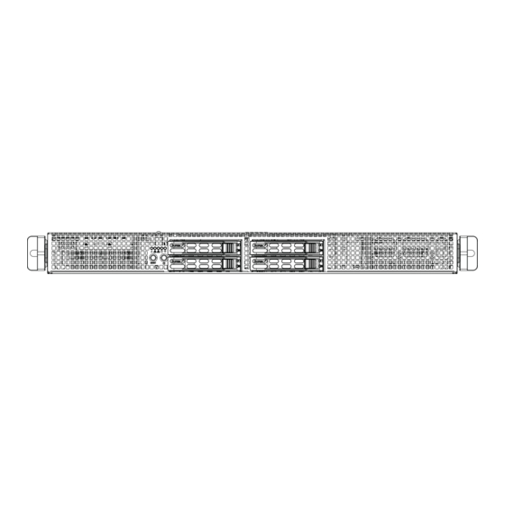
UPER ERVER 1026GT-TRF Series User's Manual Figure 6-1. Chassis: Front and Rear Views GPU Card Control Panel GPU Card Hot-Swap Drive Bays (4) PCI Slot Power Supplies Rear I/O Ports GPU Card Note: the number of PCI slots available depend on the presence of GPUs in the server model. -
Page 61: System Fan Failure
Chapter 6: Advanced Chassis Setup System Fan Failure Fan speed is controlled by system temperature via a BIOS setting. If a fan fails, the remaining fans will ramp up to full speed. Replace any failed fan at your earliest convenience with the same type and model (the system can continue to run with a failed fan). - Page 62 UPER ERVER 1026GT-TRF Series User's Manual Figure 6-3: Installing a Fan Figure 6-4: Installing the Air Shroud...
-
Page 63: Installing The Air Shroud
Chapter 6: Advanced Chassis Setup Installing the Air Shroud Air shrouds concentrate airfl ow to maximize fan effi ciency. The SC118GQ chassis air shroud does not require screws to set up Note: Each GPU card has its own air shroud. Installing the Air Shroud 1. - Page 64 UPER ERVER 1026GT-TRF Series User's Manual Figure 6-5: Removing a Hard Drive Carrier Installing a Hard Drive into a Drive Carrier 1. Remove the dummy drive, which comes pre-installed in the drive carrier, by removing the screws securing the dummy drive to the carrier. Note that these screws cannot be reused on the actual 2.5"...
- Page 65 Chapter 6: Advanced Chassis Setup Figure 6-6: Installing a Hard Drive into a Carrier Enterprise level hard disk drives are recommended for use in Supermicro chassis and servers. For information on recommended HDDs, visit the Supermicro Web site at http://www.supermicro.com/products/nfo/storage.
-
Page 66: Power Supply
UPER ERVER 1026GT-TRF Series User's Manual Power Supply The 1026GT-TRF series server includes an 1800 watt redundant power supply consisting of two power modules. Each power supply module has an auto-switching capability, which enables it to automatically sense and operate at a 100V - 240V input voltage. -
Page 67: Chapter 7 Bios
Chapter 7: BIOS Chapter 7 BIOS Introduction This chapter describes the AMI BIOS Setup Utility for the X8DTG-QF+. The AMI ROM BIOS is stored in a Flash EEPROM and can be easily updated. This chapter describes the basic navigation of the AMI BIOS Setup Utility setup screens. Starting BIOS Setup Utility To enter the AMI BIOS Setup Utility screens, press the <Delete>... -
Page 68: Main Setup
UPER ERVER 1026GT-TRF User's Manual screens. An AMI BIOS identifi cation string is displayed at the left bottom corner of the screen below the copyright message. Warning! Do not upgrade the BIOS unless your system has a BIOS-related issue. Flashing the wrong BIOS can cause irreparable damage to the system. - Page 69 Chapter 7: BIOS Use this option to change the system time and date. Highlight System Time or Sys- tem Date using the arrow keys. Enter new values through the keyboard and press <Enter>. Press the <Tab> key to move between fi elds. The date must be entered in MM/DD/YY format.
-
Page 70: Advanced Setup Confi Gurations
UPER ERVER 1026GT-TRF User's Manual Advanced Setup Confi gurations Use the arrow keys to select the Boot Setup submenu, and press <Enter> to ac- cess the following items: Boot Features Quick Boot If Enabled, this feature will skip certain tests during POST (Power-On Self Test) to reduce the time needed for system boot. - Page 71 Chapter 7: BIOS Wait For 'F1' If Error When set to Enabled, this feature forces the system to wait until the 'F1' key is pressed if an error occurs. The options are Disabled and Enabled. Hit 'Del' Message Display Select Enable to display "Press DEL to run Setup" during POST. The options are Enabled and Disabled.
- Page 72 UPER ERVER 1026GT-TRF User's Manual Processor and Clock Options This submenu allows the user to confi gure the Processor and Clock settings. Clock Spread Spectrum When this feature is enabled, BIOS will monitor and attempt to reduce the level of Electromagnetic Interference caused by the components whenever needed.
- Page 73 Chapter 7: BIOS Simultaneous Multi-Threading (Available when supported by the CPU) Select Enabled to use Intel Simultaneous Multi-Threading Technology, which will result in increased CPU performance. The options are Disabled and Enabled. Active Processor Cores Select Enabled to use a processor's Second Core and beyond. (Please refer to Intel's website for more information.) The options are All, 1 and 2.
- Page 74 UPER ERVER 1026GT-TRF User's Manual ACPI T State Select Enabled to report processor throttling in ACPI. The options are Disabled and Enabled. Advanced Chipset Control The items included in the Advanced Settings submenu are listed below: CPU Bridge Confi guration QPI Links Speed This feature selects QPI's data transfer speed.
- Page 75 Chapter 7: BIOS Patrol Scrubbing This is a memory error-correction scheme that works in the background looking for and correcting resident errors. The options are Enabled and Disabled. Throttling - Closed Loop Throttling improves reliability and reduces power use in the processor by au- tomatic voltage control during processor idle states.
- Page 76 UPER ERVER 1026GT-TRF User's Manual Active State Power Management Select Enabled to start Active-State Power Management for signal transactions between L0 and L1 Links on a PCI Express Bus. This maximizes power-saving and transaction speed. The options are Enabled and Disabled. IOH PCIE Max Payload Size Some add-on cards perform faster with the coalesce feature, which limits the payload size to 128B;...
- Page 77 Chapter 7: BIOS IDE/SATA/Floppy Confi guration When this submenu is selected, the AMI BIOS automatically detects the presence of the IDE devices and displays the following items: SATA#1 Confi guration If Compatible is selected, it sets SATA#1 to legacy compatibility mode. Select En- hanced to set SATA#1 to native SATA mode.
- Page 78 UPER ERVER 1026GT-TRF User's Manual Type This feature allows the user to select the type of device connected to the slot. Select Auto to allow the BIOS to automatically select the device type as it is detected on the slot. Select CD/DVD to confi gure the slot for CD/DVD devices. Select ARMD to use this slot for removable devices.
- Page 79 Chapter 7: BIOS DMA Mode Select Auto to allow the BIOS to automatically detect IDE DMA mode when the IDE disk drive support cannot be determined. Select SWDMA0 to allow the BIOS to use Single Word DMA mode 0. It has a data transfer rate of 2.1 MB/s.
- Page 80 UPER ERVER 1026GT-TRF User's Manual 32Bit Data Transfer Select Enable to enable 32-bit IDE data transferring support. The options are Enabled and Disabled. PCI/PnP Confi guration Clear NVRAM Select Yes to clear the NVRAM (Non-volatile random-access memory) during sys- tem boot. The options are No and Yes. Plug &...
- Page 81 Chapter 7: BIOS Load Onboard LAN 1 Option ROM/Load Onboard LAN 2 Option ROM Select Enabled to enable onboard LAN1/LAN2 Option ROMs support which will allow you to boot your systems using a network interface. The default option for LAN1 is Enabled, and for LAN2 is Disabled. Boot Graphics Adapter Priority This feature allows the user to specify which graphics controller to be used as the primary boot graphics controller.
- Page 82 UPER ERVER 1026GT-TRF User's Manual Serial Port Mode This feature allows the user to set the serial port mode for Console Redirection. The options are 115200 8, n 1; 57600 8, n, 1; 38400 8, n, 1; 19200 8, n, 1; and 9600 8, n, 1.
- Page 83 Chapter 7: BIOS 2. To avoid possible system overheating, please be sure to provide ad- equate airfl ow to your system. The options are: • The Early Alarm: Select this setting if you want the CPU overheat alarm (includ- ing the LED and the buzzer) to be triggered as soon as the CPU temperature reaches the CPU overheat threshold as predefi...
- Page 84 UPER ERVER 1026GT-TRF User's Manual The motherboard fans and CPU will run normally as confi gured in the BIOS. The fans may adjust to a faster speed depending on the Fan Speed Control settings. User intervention: No action is required. However, consider checking the CPU fans and the chassis ventilation for blockage.
- Page 85 Chapter 7: BIOS ACPI Confi guration Use this feature to confi gure Advanced Confi guration and Power Interface (ACPI) power management settings for your system. High Precision Event Timer Select Enabled to activate the High Performance Event Timer (HPET) that produces periodic interrupts at a much higher frequency than a Real-time Clock (RTC) does in synchronizing multimedia streams, providing smooth playback and reducing the de- pendency on other timestamp calculation devices, such as an x86 RDTSC Instruc-...
- Page 86 UPER ERVER 1026GT-TRF User's Manual WHEA Support Select Enabled to enable Windows Hardware Error Architecture (WHEA) support which will provide a common infrastructure to handle hardware errors on Win- dows platforms to reduce system crashes due to hardware errors and to improve system recovery and health monitoring.
- Page 87 Chapter 7: BIOS IPMI Firmware Revision This item displays the IPMI fi rmware revision used in your system. Status of BMC Baseboard Management Controller (BMC) manages the interface between system management software and platform hardware. This is an informational feature which returns the status code of the BMC micro controller.
- Page 88 UPER ERVER 1026GT-TRF User's Manual Set LAN Confi guration Use this feature to confi gure the IPMI LAN adapter with a network address as shown in the following graphics. Channel Number - This feature displays the channel number. Channel Number Status - This feature returns the channel status for the Channel Number selected above: "Channel Number is OK"...
-
Page 89: Security Settings
Chapter 7: BIOS Mark all events as read Select OK to mark all events as read. The options are OK and Cancel. Clear event log Select OK to clear all messages in the event log. The options are OK and Can- cel. - Page 90 UPER ERVER 1026GT-TRF User's Manual Change Supervisor Password Select this feature and press <Enter> to access the submenu, and then enter a new Supervisor Password. User Access Level (Available when Supervisor Password is set as above) Use this feature to set the user's access level. Select Full Access to grant the user full read and write access to the BIOS Setup Utility.
-
Page 91: Boot Confi Guration
Chapter 7: BIOS Boot Confi guration Use this feature to confi gure boot priority settings. Boot Device Priority Use this feature to specify the sequence of boot priority for onboard devices. The settings are 1st boot device~5th boot device and Disabled. •... - Page 92 UPER ERVER 1026GT-TRF User's Manual CD/DVD Drives This feature allows the user to specify the boot sequence from available CD/DVD Drives (i.e., 1st Drive, 2nd Drive, etc). • 1st Boot Device/2nd Boot Device/3rd Boot Device USB Drives Use this feature to specify the boot sequence from available USB drives. The set- tings are 1st boot device, 2nd boot device, and Disabled.
-
Page 93: Exit Options
Chapter 7: BIOS Exit Options Select the Exit tab from the BIOS Setup Utility screen to enter the Exit screen. Save Changes and Exit When you have completed the system confi guration changes, select this option to leave the BIOS Setup Utility and reboot the computer for the new system confi gura- tion parameters to take effect. - Page 94 UPER ERVER 1026GT-TRF User's Manual Notes 7-28...
-
Page 95: Appendix A Bios Post Error Codes
Appendix A: BIOS POST Error Codes Appendix A BIOS POST Error Codes During the POST (Power-On Self-Test) routines, which are performed each time the system is powered on, errors may occur. Non-fatal errors are those which, in most cases, allow the system to continue the boot-up process. - Page 96 UPER ERVER 1026GT-TRF User's Manual Notes...
-
Page 97: Appendix B System Specifi Cations
Appendix B: System Specifi cations Appendix B System Specifi cations Processors Two Intel Xeon 5600/5500 series processors Note: Please refer to our web site for a complete listing of supported processors. Chipset Dual Intel 5520 + ICH10R BIOS 32 Mb AMIBIOS® SPI Flash ROM Memory Capacity Six DIMM sockets supporting up to 96 GB of registered ECC or up to 24 GB of unbuffered ECC/non-ECC DDR3-1333/1066/800 SDRAM... - Page 98 UPER ERVER 1026GT-TRF User's Manual System Cooling Ten sets of 4-cm counter-rotating cooling fans (fan speed controlled by BIOS setting) System Input Requirements AC Input Voltage: 180-240 VAC Rated Input Current: 1000W: 100-120V/12-10A, 1200W: 120-140V/12-10A, 1800W: 200-240V/10-8.5A Rated Input Frequency: 50-60 Hz Power Supply Rated Output Power: 1800W (Part# PWS-1K81P-1R) Rated Output Voltages: +12V (150A), +5Vsb (4A)
- Page 99 Appendix B: System Specifi cations (continued from front) The products sold by Supermicro are not intended for and will not be used in life support systems, medical equipment, nuclear facilities or systems, aircraft, aircraft devices, aircraft/emergency com- munication devices or other critical systems whose failure to perform be reasonably expected to result in signifi...
- Page 100 UPER ERVER 1026GT-TRF User's Manual Notes...
Need help?
Do you have a question about the SUPERSERVER 1026GT-TRF and is the answer not in the manual?
Questions and answers