Table of Contents
Advertisement
Quick Links
Advertisement
Table of Contents

Related Manuals for Supero SUPERSERVER 1027R-WC1NR


Summary of Contents for Supero SUPERSERVER 1027R-WC1NR
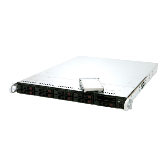
- Page 1 UPER ® ® UPER ERVER 1027R-WC1NR 1027R-WC1NRT USER’S MANUAL 1.0a...
- Page 2 The information in this User’s Manual has been carefully reviewed and is believed to be accurate. The vendor assumes no responsibility for any inaccuracies that may be contained in this document, makes no commitment to update or to keep current the information in this manual, or to notify any person or organization of the updates.
- Page 3 It provides information for the installation and use of the SuperServer 1027R- WC1NR/1027R-WC1NRT. Installation and maintainance should be performed by experienced technicians only. The SuperServer 1027R-WC1NR/1027R-WC1NRT is a high-end server based on the SC116AC2-R700WB 1U rackmount chassis and the X9DRW-CF31/CTF31 dual processor serverboard.
- Page 4 UPER ERVER 1027R-WC1NR/1027R-WC1NRT User's Manual Chapter 5: Advanced Serverboard Setup Chapter 5 provides detailed information on the X9DRW-CF31/CTF31 serverboard, including the locations and functions of connections, headers and jumpers. Refer to this chapter when adding or removing processors or main memory and when reconfi...
- Page 5 Preface Notes...
-
Page 6: Table Of Contents
UPER ERVER 1027R-WC1NR/1027R-WC1NRT User's Manual Table of Contents Chapter 1 Introduction Overview ......................1-1 Serverboard Features ..................1-2 Processors ...................... 1-2 Memory ......................1-2 SAS ......................... 1-2 Serial ATA ......................1-2 PCIe Expansion Slots ..................1-2 Rear I/O Ports ....................1-3 Server Chassis Features ................ - Page 7 Table of Contents Control Panel Buttons ..................3-1 Power ......................3-1 UID ........................3-2 Control Panel LEDs ..................3-2 Universal Information LED ................3-2 NIC1 ........................ 3-3 NIC2 ........................ 3-3 HDD ......................... 3-3 Power ......................3-3 Hard Drive Carrier LEDs ................. 3-4 Hard Drives .....................
- Page 8 UPER ERVER 1027R-WC1NR/1027R-WC1NRT User's Manual Memory Support ....................5-8 DIMM Installation .................... 5-8 Adding PCIe Add-On Cards ................5-11 Serverboard Details ..................5-12 X9DRW-CF31/CTF31 Quick Reference ............5-12 Connector Defi nitions ................... 5-14 Jumper Settings .................... 5-20 5-10 Onboard Indicators ..................5-23 5-11 SATA and SAS Ports ..................
-
Page 9: Chapter 1 Introduction
Chapter 1 Introduction Overview The SuperServer 1027R-WC1NR/1027R-WC1NRT is comprised of two main sub- systems: the SC116AC2-R700WB 1U chassis and the X9DRW-CF31/CTF31 dual processor serverboard. Please refer to our web site for information on operating systems that have been certifi ed for use with the system (www.supermicro.com). -
Page 10: Serverboard Features
UPER ERVER 1027R-WC1NR/1027R-WC1NRT User's Manual Serverboard Features The SuperServer 1027R-WC1NR/1027R-WC1NRT is built around the X9DRW- CF31/CTF31, a dual processor serverboard based on the Intel C602J chipset and designed to provide maximum performance. Below are the main features of the X9DRW-CF31/CTF31. (See Figure 1-1 for a block diagram of the chipset.) Processors The X9DRW-CF31/CTF31 supports single or dual Intel®... -
Page 11: Pcie Expansion Slots
Chapter 1: Introduction Server Chassis Features The SC116AC2-R700WB is Supermicro's third-generation 1U chassis. The follow- ing is a general outline of the main features of the SC116AC2-R700WB chassis. System Power The SC116AC2-R700WB features a 700W power supply composed of two separate power modules to provide power redundancy. - Page 12 UPER ERVER 1027R-WC1NR/1027R-WC1NRT User's Manual Figure 1-1. Intel C602J Chipset: System Block Diagram Note: This is a general block diagram. Please see Chapter 5 for details. RIGHT SLOT LEFT SLOT 8 GT/s PCIE 3.0x16 8 GT/s PCIE 3.0x16 PE2 PE1 CPU Rear U7C1 Socket 01...
-
Page 13: Contacting Supermicro
Chapter 1: Introduction Contacting Supermicro Headquarters Address: Super Micro Computer, Inc. 980 Rock Ave. San Jose, CA 95131 U.S.A. Tel: +1 (408) 503-8000 Fax: +1 (408) 503-8008 Email: marketing@supermicro.com (General Information) support@supermicro.com (Technical Support) Web Site: www.supermicro.com Europe Address: Super Micro Computer B.V. Het Sterrenbeeld 28, 5215 ML 's-Hertogenbosch, The Netherlands Tel:... - Page 14 UPER ERVER 1027R-WC1NR/1027R-WC1NRT User's Manual Notes...
-
Page 15: Chapter 2 Server Installation
Unpacking the System You should inspect the box the SuperServer 1027R-WC1NR/1027R-WC1NRT was shipped in and note if it was damaged in any way. If the server itself shows damage you should fi... -
Page 16: Warnings And Precautions
UPER ERVER 1027R-WC1NR/1027R-WC1NRT User's Manual • This product is for installation only in a Restricted Access Location (dedicated equipment rooms, service closets and the like). • This product is not suitable for use with visual display work place devices acccording to §2 of the the German Ordinance for Work with Visual Display Units. Warnings and Precautions Rack Precautions •... -
Page 17: Rack Mounting Considerations
Chapter 2: Server Installation Rack Mounting Considerations Ambient Operating Temperature If installed in a closed or multi-unit rack assembly, the ambient operating tempera- ture of the rack environment may be greater than the ambient temperature of the room. Therefore, consideration should be given to installing the equipment in an environment compatible with the manufacturer’s maximum rated ambient tempera- ture (Tmra). -
Page 18: Rack Mounting Instructions
UPER ERVER 1027R-WC1NR/1027R-WC1NRT User's Manual Rack Mounting Instructions This section provides information on installing the SC116 chassis into a rack unit with the rails provided. There are a variety of rack units on the market, which may mean the assembly procedure will differ slightly. You should also refer to the installation instructions that came with the rack unit you are using. -
Page 19: Inner Rail Extension
Chapter 2: Server Installation Figure 2-2. Identifying the Sections of the Rack Rails (right side rail shown) Inner Rail Extension The SC116 chassis includes a set of inner rails in two sections: inner rails and inner rail extensions. The inner rails are pre-attached and do not interfere with normal use of the chassis if you decide not to use a server rack. -
Page 20: Outer Rails
UPER ERVER 1027R-WC1NR/1027R-WC1NRT User's Manual Secure to the Front of the Rack Secure to the Rear of the Rack Attach Outer Rails together Figure 2-3. Assembling the Outer Rails Outer Rails Installing the Outer Rails to the Rack 1. Attach the shorter outer rail to the outside of the longer outer rail. You must align the pins with the slides. - Page 21 Chapter 2: Server Installation Figure 2-4. Installing the Outer Rails to the Server Rack Note: fi gures are for illustrative purposes only. Always install servers to the bottom of a rack fi rst.
-
Page 22: Installing The Chassis Into A Rack
UPER ERVER 1027R-WC1NR/1027R-WC1NRT User's Manual Figure 2-5. Installing the Rack Rails Installing the Chassis into a Rack 1. Confi rm that chassis includes the inner rails and inner rail extensions. Also- confi rm that the outer rails are installed on the rack. 2. -
Page 23: Installing The Chassis Into A Telco Rack
Chapter 2: Server Installation Installing the Chassis into a Telco rack To install the chassis into a Telco or post-style rack, use two L-shaped brackets on either side of the chassis (four total). 1. First, determine how far follow the server will extend out the front of the rack. Larger chassis should be positioned to balance the weight between front and back. - Page 24 UPER ERVER 1027R-WC1NR/1027R-WC1NRT User's Manual Figure 2-6. Installing the Chassis into a Telco Rack Note: fi gures are for illustrative purposes only. Always install servers to the bottom of a rack fi rst. 2-10...
-
Page 25: Chapter 3 System Interface
Chapter 3: System Interface Chapter 3 System Interface Overview There are several LEDs on the control panel and on the drive carriers that provide system and component status for the server. This chapter explains the meanings of all LED indicators and the appropriate responses that need to be taken. Control Panel Buttons There are two buttons located on the front of the chassis: a power on/off button and a UID button. -
Page 26: Uid
UPER ERVER 1027R-WC1NR/1027R-WC1NRT User's Manual Depressing the UID (Unit Identifi er) button illuminates an LED on both the front and rear of the chassis for easy system location in large stack confi gurations. The LED will remain on until the button is pushed a second time. Another UID button on the rear of the chassis serves the same function. -
Page 27: Nic1
Chapter 3: System Interface Universal Information LED States State Indication Fast Blinking Red (1x/sec) Fan Fail Solid Red CPU Overheat Slow Blinking Red (1x/4 sec) Power Fail Solid Blue Local UID Button Depressed Blinking Blue IPMI-Activated UID NIC1 Indicates network activity on GLAN1 when fl ashing. NIC2 Indicates network activity on GLAN2 when fl... -
Page 28: Hard Drive Carrier Leds
UPER ERVER 1027R-WC1NR/1027R-WC1NRT User's Manual Hard Drive Carrier LEDs The SC116AC chassis supports the use of 10 SAS/SATA/NVMe PCI SSD drives. Hard Drives Each hard drive carrier has two LEDs. • Blue: When illuminated, this blue LED (on the front of the hard drive carrier) indicates drive activity. -
Page 29: Chapter 4 Standardized Warning Statements For Ac Systems
Chapter 4: Warning Statements for AC Systems Chapter 4 Standardized Warning Statements for AC Systems About Standardized Warning Statements The following statements are industry standard warnings, provided to warn the user of situations which have the potential for bodily injury. Should you have questions or experience difficulty, contact Supermicro's Technical Support department for assistance. - Page 30 UPER ERVER 1027R-WC1NR/1027R-WC1NRT User's Manual Warnung WICHTIGE SICHERHEITSHINWEISE Dieses Warnsymbol bedeutet Gefahr. Sie befi nden sich in einer Situation, die zu Verletzungen führen kann. Machen Sie sich vor der Arbeit mit Geräten mit den Gefahren elektrischer Schaltungen und den üblichen Verfahren zur Vorbeugung vor Unfällen vertraut.
- Page 31 Warning Statements for AC Systems ﺟﺴﺪﻳﺔ ﺍﺻﺎﺑﺔ ﺗﺘﺴﺒﺐ ﻓﻲ ﺣﺎﻟﺔ ﻳﻤﻜﻦ ﺃﻥ ﺍﻧﻚ ﻓﻲ ﺧﻄﺮ ﻳﻌﻨﻲ ﻫﺬﺍ ﺍﻟﺮﻣﺰ !ﺗﺤﺬﻳﺮ ﺍﻟﺪﻭﺍﺋﺮ ﺑﺎﻟﻤﺨﺎﻁﺮ ﺍﻟﻨﺎﺟﻤﺔ ﻋﻦ ﻦ ﻋﻠﻰ ﻋﻠﻢ ، ﻛ ﻣﻌﺪﺍﺕ ﺗﻌﻤﻞ ﻋﻠﻰ ﺃﻱ ﻗﺒﻞ ﺃﻥ ﺍﻟﻜﻬﺮﺑﺎﺋﻴﺔ ﺣﻮﺍﺩﺙ ﺃﻱ ﻭﻗﻮﻉ ﻤﻨﻊ ﻟ ﺍﻟﻮﻗﺎﺋﻴﺔ...
-
Page 32: Installation Instructions
UPER ERVER 1027R-WC1NR/1027R-WC1NRT User's Manual Installation Instructions Warning! Read the installation instructions before connecting the system to the power source. 設置手順書 システムを電源に接続する前に、 設置手順書をお読み下さい。 警告 将此系统连接电源前,请先阅读安装说明。 警告 將系統與電源連接前,請先閱讀安裝說明。 Warnung Vor dem Anschließen des Systems an die Stromquelle die Installationsanweisungen lesen. ¡Advertencia! Lea las instrucciones de instalación antes de conectar el sistema a la red de alimentación. -
Page 33: Circuit Breaker
Chapter 4: Warning Statements for AC Systems Circuit Breaker Warning! This product relies on the building's installation for short-circuit (overcurrent) protection. Ensure that the protective device is rated not greater than: 250 V, 20 A. サーキッ ト ・ ブレーカー この製品は、 短絡 (過電流) 保護装置がある建物での設置を前提としています。 保護装置の定格が250 V、... -
Page 34: Power Disconnection Warning
UPER ERVER 1027R-WC1NR/1027R-WC1NRT User's Manual 경고! 이 제품은 전원의 단락(과전류)방지에 대해서 전적으로 건물의 관련 설비에 의존합니다. 보호장치의 정격이 반드시 250V(볼트), 20A(암페어)를 초과하지 않도록 해야 합니다. Waarschuwing Dit product is afhankelijk van de kortsluitbeveiliging (overspanning) van uw electrische installatie. Controleer of het beveiligde aparaat niet groter gedimensioneerd is dan 220V, 20A. - Page 35 Chapter 4: Warning Statements for AC Systems ¡Advertencia! El sistema debe ser disconnected de todas las fuentes de energía y del cable eléctrico quitado de los módulos de fuente de alimentación antes de tener acceso el interior del chasis para instalar o para quitar componentes de sistema. Attention Le système doit être débranché...
-
Page 36: Equipment Installation
UPER ERVER 1027R-WC1NR/1027R-WC1NRT User's Manual Equipment Installation Warning! Only trained and qualifi ed personnel should be allowed to install, replace, or service this equipment. 機器の設置 トレーニングを受け認定された人だけがこの装置の設置、 交換、 またはサービスを許可 されています。 警告 只有经过培训且具有资格的人员才能进行此设备的安装、更换和维修。 警告 只有經過受訓且具資格人員才可安裝、更換與維修此設備。 Warnung Das Installieren, Ersetzen oder Bedienen dieser Ausrüstung sollte nur geschultem, qualifi... -
Page 37: Restricted Area
Chapter 4: Warning Statements for AC Systems Waarschuwing Deze apparatuur mag alleen worden geïnstalleerd, vervangen of hersteld door geschoold en gekwalifi ceerd personeel. Restricted Area Warning! This unit is intended for installation in restricted access areas. A restricted access area can be accessed only through the use of a special tool, lock and key, or other means of security. -
Page 38: Battery Handling
UPER ERVER 1027R-WC1NR/1027R-WC1NRT User's Manual אזור עם גישה מוגבלת !אזהרה יש להתקין את היחידה באזורים שיש בהם הגבלת גישה. הגישה ניתנת בעזרת .('כלי אבטחה בלבד )מפתח, מנעול וכד ﻣﺤﻈﻮﺭﺓ ﻣﻨﺎﻁﻖ ﻟﺘﺮﻛﻴﺒﻬﺎ ﻓﻲ ﻫﺬﻩ ﺍﻟﻮﺣﺪﺓ ﺗﺨﺼﻴﺺ ﺗﻢ ،ﺃﺩﺍﺓ ﺧﺎﺻﺔ ﻣﻦ ﺧﻼﻝ ﺍﺳﺘﺨﺪﺍﻡ ﻓﻘﻂ... - Page 39 Chapter 4: Warning Statements for AC Systems Warnung Bei Einsetzen einer falschen Batterie besteht Explosionsgefahr. Ersetzen Sie die Batterie nur durch den gleichen oder vom Hersteller empfohlenen Batterietyp. Entsorgen Sie die benutzten Batterien nach den Anweisungen des Herstellers. Attention Danger d'explosion si la pile n'est pas remplacée correctement. Ne la remplacer que par une pile de type semblable ou équivalent, recommandée par le fabricant.
-
Page 40: Redundant Power Supplies
UPER ERVER 1027R-WC1NR/1027R-WC1NRT User's Manual Redundant Power Supplies Warning! This unit might have more than one power supply connection. All connections must be removed to de-energize the unit. 冗長電源装置 このユニッ トは複数の電源装置が接続されている場合があります。 ユニッ トの電源を切るためには、 すべての接続を取り外さなければなりません。 警告 此部件连接的电源可能不止一个,必须将所有电源断开才能停止给该部件供电。 警告 此裝置連接的電源可能不只一個,必須切斷所有電源才能停止對該裝置的供電。 Warnung Dieses Gerät kann mehr als eine Stromzufuhr haben. Um sicherzustellen, dass der Einheit kein trom zugeführt wird, müssen alle Verbindungen entfernt werden. -
Page 41: Backplane Voltage
Chapter 4: Warning Statements for AC Systems ﺍﻣﺪﺍﺩ ﺍﻟﻄﺎﻗﺔ ﺑﻮﺣﺪﺍﺕ ﻋﺪﺓ ﺍﺗﺼﺎﻻﺕ ﺠﻬﺎﺯ ﺍﻟ ﻳﻜﻮﻥ ﻟﻬﺬﺍ ﻗﺪ ﺍﻟﻜﻬﺮﺑﺎء ﻋﻦ ﻮﺣﺪﺓ ﺍﻟ ﻟﻌﺰﻝ ﻛﺎﻓﺔ ﺍﻻﺗﺼﺎﻻﺕ ﻳﺠﺐ ﺇﺯﺍﻟﺔ 경고! 이 장치에는 한 개 이상의 전원 공급 단자가 연결되어 있을 수 있습니다. 이 장치에 전원을... -
Page 42: Comply With Local And National Electrical Codes
UPER ERVER 1027R-WC1NR/1027R-WC1NRT User's Manual מתח בפנל האחורי !הרה אז קיימת סכנת מתח בפנל האחורי בזמן תפעול המערכת. יש להיזהר במהלך .העבודה ﺍﻟﻠﻮﺣﺔ ﺃﻭﺍﻟﻄﺎﻗﺔ ﺍﻟﻤﻮﺟﻮﺩﺓ ﻋﻠﻰ ﺍﻟﺘﻴﺎﺭ ﺍﻟﻜﻬﺮﺑﺎﺋﻲ ﻣﻦ ﺧﻄﺮ ﻫﻨﺎﻙ ﻫﺬﺍ ﺍﻟﺠﻬﺎﺯ ﺧﺪﻣﺔ ﻛﻦ ﺣﺬﺭﺍ ﻋﻨﺪ ﻳﻌﻤﻞ ﺍﻟﻨﻈﺎﻡ ﻋﻨﺪﻣﺎ ﻳﻜﻮﻥ 경고! 시스템이... -
Page 43: Product Disposal
Chapter 4: Warning Statements for AC Systems Attention L'équipement doit être installé conformément aux normes électriques nationales et locales. תיאום חוקי החשמל הארצי !אזהרה הציוד חייבת להיות תואמת לחוקי החשמל המקומיים והארציים התקנת ﺍﻟﻤﺘﻌﻠﻘﺔ ﺍﻟﻤﺤﻠﻴﺔ ﻭﺍﻟﻮﻁﻨﻴﺔ ﻘﻮﺍﻧﻴﻦ ﻳﺠﺐ ﺃﻥ ﻳﻤﺘﺜﻞ ﻟﻠ ﺍﻟﻜﻬﺮﺑﺎﺋﻴﺔ... -
Page 44: Hot Swap Fan Warning
UPER ERVER 1027R-WC1NR/1027R-WC1NRT User's Manual ¡Advertencia! Al deshacerse por completo de este producto debe seguir todas las leyes y reglamentos nacionales. Attention La mise au rebut ou le recyclage de ce produit sont généralement soumis à des lois et/ou directives de respect de l'environnement. Renseignez-vous auprès de l'organisme compétent. - Page 45 Chapter 4: Warning Statements for AC Systems 警告 當您從機架移除風扇裝置,風扇可能仍在轉動。小心不要將手指、螺絲起子和其他 物品太靠近風扇。 Warnung Die Lüfter drehen sich u. U. noch, wenn die Lüfterbaugruppe aus dem Chassis genommen wird. Halten Sie Finger, Schraubendreher und andere Gegenstände von den Öffnungen des Lüftergehäuses entfernt. ¡Advertencia! Los ventiladores podran dar vuelta cuando usted quite ell montaje del ventilador del chasis.
-
Page 46: Power Cable And Ac Adapter
UPER ERVER 1027R-WC1NR/1027R-WC1NRT User's Manual Power Cable and AC Adapter Warning! When installing the product, use the provided or designated connection cables, power cables and AC adaptors. Using any other cables and adaptors could cause a malfunction or a fi re. Electrical Appliance and Material Safety Law prohibits the use of UL or CSA -certifi... - Page 47 Chapter 4: Warning Statements for AC Systems Attention Lors de l'installation du produit, utilisez les bables de connection fournis ou désigné. L'utilisation d'autres cables et adaptateurs peut provoquer un dysfonctionnement ou un incendie. Appareils électroménagers et de loi sur la sécurité Matériel interdit l'utilisation de UL ou CSA câbles certifi...
- Page 48 UPER ERVER 1027R-WC1NR/1027R-WC1NRT User's Manual Notes 4-20...
-
Page 49: Chapter 5 Advanced Serverboard Setup
Chapter 5: Advanced Serverboard Setup Chapter 5 Advanced Serverboard Setup This chapter covers the steps required to connect the data and power cables and install add-on cards. All serverboard jumpers and connections are also described. A layout and quick reference chart are included in this chapter for your reference. Remember to completely close the chassis when you have fi... -
Page 50: Connecting Cables
UPER ERVER 1027R-WC1NR/1027R-WC1NRT User's Manual Connecting Cables Now that the serverboard is installed, the next step is to connect the cables to the board. These include the data cables for the peripherals and control panel and the power cables. Connecting Data Cables The cables used to transfer data from the peripheral devices have been carefully routed to prevent them from blocking the fl... -
Page 51: Rear I/O Ports
Chapter 5: Advanced Serverboard Setup Figure 5-1. Control Panel Header Pins Ground 3.3 V FP PWRLED 3/3V Stby HDD LED NIC1 Link LED NIC1 Activity LED NIC2 Activity LED NIC2 Link LED OH/Fan Fail/ Blue (UID) LED Cathode PWR FaiL LED Power Fail LED 3.3V Reset... -
Page 52: Installing The Processor And Heatsink
UPER ERVER 1027R-WC1NR/1027R-WC1NRT User's Manual Installing the Processor and Heatsink Caution: When handling the processor package, avoid placing direct pressure on the label area of the fan. Notes: • Always connect the power cord last and always remove it before adding, re- moving or changing any hardware components. - Page 53 Chapter 5: Advanced Serverboard Setup 3. With the lever labeled 'Close 1st' fully retracted, gently push down on the 'Open 1st' lever to open the load plate. Lift the load plate to open it completely. Gently push 4. Using your thumb and the index down to pop the load plate fi...
-
Page 54: Installing And Removing A Passive Cpu Heatsink
UPER ERVER 1027R-WC1NR/1027R-WC1NRT User's Manual 7. With the CPU in the socket, in- Gently close spect the four corners of the CPU the load plate. to make sure that they are fl ush with the socket. 8. Close the load plate. Use your thumb to gently push the lever labeled 'Close 1st' then the lever labeled 'Open 1st' down until they... - Page 55 Chapter 5: Advanced Serverboard Setup 2. Gently wriggle the heatsink to loosen it from the CPU (do not use excessive force). Once the CPU is loose, remove the it from the CPU socket. 3. Clean the surface of the CPU and the heatsink to remove the used thermal grease.
-
Page 56: Installing Memory
UPER ERVER 1027R-WC1NR/1027R-WC1NRT User's Manual Installing Memory Caution! Exercise extreme care when installing or removing DIMM modules to prevent any possible damage. Memory Support The X9DRW-CF31/CTF31 supports up to 1024 GB of ECC Load-Reduced (LRDIMM), up to 512 GB of ECC Registered (RDIMM) or up to 128 GB of ECC/ non-ECC unbuffered (UDIMM) DDR3-1866/1600/1333/1066/800 SDRAM in 16 DIMM sockets. - Page 57 Chapter 5: Advanced Serverboard Setup DIMM Module Population Table Follow the tables below when installing memory. Processors and their Corresponding Memory Modules CPU# Corresponding DIMM Modules CPU 1 DIMMA1 DIMMA2 DIMMB1 DIMMB2 DIMMC1 DIMMC2 DIMMD1 DIMMD2 CPU2 DIMME1 DIMME2 DIMMF1 DIMMF2 DIMMG1 DIMMG2...
- Page 58 UPER ERVER 1027R-WC1NR/1027R-WC1NRT User's Manual Notes: Using DDR3 DIMMs with different operating frequencies is not allowed. All channels in a system will run at the lowest common frequency. Due to memory allocation to system devices, the amount of memory that remains available for operational use will be reduced when 4 GB of RAM is used.
-
Page 59: Adding Pcie Add-On Cards
Chapter 5: Advanced Serverboard Setup Adding PCIe Add-On Cards The 1027R-WC1NR/1027R-WC1NRT can accommodate one full-height, half-length PCIe 3.0 x16 profi le add-on (expansion) card installed to the riser card included in the system. Installing an Add-on Card 1. Begin by removing the shield located by the riser card. 2. -
Page 60: Serverboard Details
UPER ERVER 1027R-WC1NR/1027R-WC1NRT User's Manual Serverboard Details Figure 5-6. X9DRW-CF31/CTF31 Layout LAN1 USB2/3 USB0/1 LAN2 LED3 i350 (-CF31) X540 (-CTF31) COM1 IPMI_LAN CLOSE 1st CPU2 OPEN 1st JBAT1 X9DRW-CF31 BAR CODE Rev. 1.00 JSD1 JBT1 BIOS CLOSE 1st Intel CPU1 OPEN 1st FAN1 Notes... - Page 61 Chapter 5: Advanced Serverboard Setup Jumper Description Default Setting JBT1 Clear CMOS See Section 5-9 C1/JI SMB to PCI-E Slots Pins 2-3 (Normal) JPB1 BMC Enable/Disable Pins 1-2 (Enabled) JPG1 VGA Enable/Disable Pins 1-2 (Enabled) JPL1 LAN1/LAN2 Enable/Disable Pins 1-2 (Enabled) Management Engine (ME) Re- JPME1 Pins 1-2 (Normal)
-
Page 62: Connector Defi Nitions
UPER ERVER 1027R-WC1NR/1027R-WC1NRT User's Manual Connector Defi nitions Power Connectors ATX Power 24-pin Connector Pin Defi nitions A 24-pin main power supply connector Pin# Defi nition Pin # Defi nition (JPW1), two 8-pin CPU power con- +3.3V +3.3V nectors (JPW2/3) must be connected -12V +3.3V to the power supply. - Page 63 Chapter 5: Advanced Serverboard Setup PWR Fail LED Power Fail LED Pin Defi nitions (JF1) The Power Fail LED connection is lo- Pin# Defi nition cated on pins 5 and 6 of JF1. See the 3.3V table on the right for pin defi nitions. Signal Overheat (OH)/Fan Fail/PWR Fail/ OH/Fan Fail/ PWR Fail/Blue_UID...
- Page 64 UPER ERVER 1027R-WC1NR/1027R-WC1NRT User's Manual Power On LED The Power On LED connector is lo- Power LED cated on pins 15 and 16 of JF1 (use Pin Defi nitions (JF1) JLED for a 3-pin connector). This Pin# Defi nition connection is used to provide LED 3.3V indication of power being supplied to Control...
- Page 65 Chapter 5: Advanced Serverboard Setup LAN Ports Ethernet Ports Pin Defi nition Pin# Defi nition Pin# Defi nition Two Ethernet ports are located on P2V5SB SGND the I/O backplane. LAN ports 1/2 TD0+ Act LED support gigabit LAN connections on the C9DRW-CF31, and support TD0- P3V3SB 10 Gigabit LAN connections on the...
- Page 66 UPER ERVER 1027R-WC1NR/1027R-WC1NRT User's Manual Serial Port Pin Defi nitions (COM1/COM2) Serial Ports Pin # Defi nition Pin # Defi nition One serial port is located next to the VGA port. COM1 provides support for a serial connection. See the table on the right for pin defi...
- Page 67 Chapter 5: Advanced Serverboard Setup TPM/Port 80 Header Pin Defi nitions Pin # Defi nition Pin # Defi nition TPM Header/Port 80 LCLK A Trusted Platform Module/Port 80 LFRAME# <(KEY)> header is located at JTPM1 to provide LRESET# +5V (X) TPM support and a Port 80 connec- LAD 3 LAD 2...
-
Page 68: Jumper Settings
UPER ERVER 1027R-WC1NR/1027R-WC1NRT User's Manual Standby Power Header Standby PWR Pin Defi nitions The +5V Standby Power header is lo- Pin# Defi nition cated at JSTBY1. See the table on the +5V Standby right for pin defi nitions. (You must also Ground have a card with a Standby Power con- Wake-up... - Page 69 Chapter 5: Advanced Serverboard Setup CMOS Clear JBT1 is used to clear CMOS (which will also clear any passwords). Instead of pins, this jumper consists of contact pads to prevent accidentally clearing the contents of CMOS. To clear CMOS, 1. First power down the system and unplug the power cord(s). 2.
- Page 70 UPER ERVER 1027R-WC1NR/1027R-WC1NRT User's Manual BMC Enable Jumper JPB1 allows you to enable BMC Enable the embedded the Winbond WPCM Jumper Settings 450 BMC (Baseboard Management Jumper Setting Defi nition Controller) to provide IPMI 2.0/KVM Pins 1-2 BMC Enabled support. See the table on the right for Pins 2-3 Disabled jumper settings.
-
Page 71: 5-10 Onboard Indicators
Chapter 5: Advanced Serverboard Setup 5-10 Onboard Indicators Link LED Activity LED LAN LEDs The Ethernet ports (located beside the VGA port) have two LEDs. On each LAN 1/LAN 2 Link LED (Left) LED State port, the yellow LED fl ashes to indi- LED Color Defi... -
Page 72: 5-11 Sata And Sas Ports
UPER ERVER 1027R-WC1NR/1027R-WC1NRT User's Manual Unit Identifi cation Switch/LED A Unit Identifi er switch (UID) and a rear UID LED indicator (LED3) are located next to LAN ports on the back UID LED Status of the chassis. When the user pushes Color/State OS Status the rear UID switch, the rear UID LED... -
Page 73: 5-12 Installing Software
Chapter 5: Advanced Serverboard Setup 5-12 Installing Software The Supermicro ftp site contains drivers and utilities for your system at ftp://ftp. supermicro.com. Some of these must be installed, such as the chipset driver. After accessing the ftp site, go into the CDR_Images directory and locate the ISO fi... -
Page 74: Superdoctor® 5
UPER ERVER 1027R-WC1NR/1027R-WC1NRT User's Manual SuperDoctor® 5 The Supermicro SuperDoctor 5 is a program that functions in a command-line or web-based interface in Windows and Linux operating systems. The program moni- tors system health information such as CPU temperature, system voltages, system power consumption, fan speed, and provides alerts via email or Simple Network Management Protocol (SNMP). -
Page 75: 5-13 Onboard Battery
Chapter 5: Advanced Serverboard Setup 5-13 Onboard Battery Please handle used batteries carefully. Do not damage the battery in any way; a damaged battery may release hazardous materials into the environment. Do not discard a used battery in the garbage or a public landfi ll. Please comply with the regulations set up by your local hazardous waste management agency to dispose of your used battery properly. - Page 76 UPER ERVER 1027R-WC1NR/1027R-WC1NRT User's Manual Notes 5-28...
-
Page 77: Chapter 6 Advanced Chassis Setup
Chapter 6: Advanced Chassis Setup Chapter 6 Advanced Chassis Setup This chapter covers the steps required to install components and perform mainte- nance on the SC116AC2-R700WB chassis. For component installation, follow the steps in the order given to eliminate the most common problems encountered. If some steps are unnecessary, skip ahead to the step that follows. -
Page 78: Control Panel
UPER ERVER 1027R-WC1NR/1027R-WC1NRT User's Manual Figure 6-1. Front and Rear Chassis Views Control Panel Hot-Swap Drive Bays (10) USB Ports PCIe Expansion Slots (w/ Riser Card) Power Supplies Rear I/O Ports (see Section 5-3) Control Panel The control panel (located on the front of the chassis) must be connected to the JF1 connector on the serverboard to provide you with system status indications. -
Page 79: System Fans
Chapter 6: Advanced Chassis Setup Figure 6-2. Removing the Chassis Cover Warning: Except for short periods of time, do NOT operate the server without the cover in place. The chassis cover must be in place to allow proper airfl ow and prevent overheating. - Page 80 UPER ERVER 1027R-WC1NR/1027R-WC1NRT User's Manual Replacing a System Fan 1. Open the chassis while the system is running to determine which fan has failed. Never run the server for an extended period of time with the chassis open. 2. Turn off the power to the system and unplug the power cord from the power supply.
-
Page 81: Checking The Airfl Ow
Chapter 6: Advanced Chassis Setup Checking the Airfl ow Check the Airfl ow 1. Make sure there are no objects obstructing the airfl ow in and out of the server. In addition, if you are using a front bezel, make sure the bezel's fi lter is replaced periodically. -
Page 82: Hard Drive Installation
UPER ERVER 1027R-WC1NR/1027R-WC1NRT User's Manual Hard Drive Installation The hard drives are mounted in drive carriers to simplify their installation and removal from the chassis. These carriers also help promote proper airfl ow for the drive bays. For this reason, even empty carriers without drives installed must remain in the chassis. - Page 83 Chapter 6: Advanced Chassis Setup Removing a Hard Drive 1. To remove a carrier, push the release button located beside the drive LEDs. 2. Swing the handle fully out and use it to pull the unit straight out. Note: Your operating system must have RAID support to enable the hot-plug ca- pability of the hard drives.
-
Page 84: Power Supply
UPER ERVER 1027R-WC1NR/1027R-WC1NRT User's Manual Power Supply The SC116 chassis comes equipped with two redundant 700W-750W power sup- plies. These power supplies are auto-switching capable and automatically sense and operate at a 100v to 240v input voltage. An amber light will be illuminated on the power supply when the power is off. -
Page 85: Chapter 7 Bios
Chapter 7: BIOS Chapter 7 BIOS Introduction This chapter describes the AMI BIOS setup utility for the X9DRW-CF31/X9DRW- CTF31. It also provides the instructions on how to navigate the AMI BIOS setup utility screens. The AMI ROM BIOS is stored in a Flash EEPROM and can be easily updated. -
Page 86: Main Setup
UPER ERVER 1027R-WC1NR/1027R-WC1NRT User's Manual Main Setup When you fi rst enter the AMI BIOS setup utility, you will enter the Main setup screen. You can always return to the Main setup screen by selecting the Main tab on the top of the screen. -
Page 87: Advanced Setup Confi Gurations
Chapter 7: BIOS Advanced Setup Confi gurations Use the arrow keys to select Advanced Setup and press <Enter> to access the following submenu items. Boot Features Quiet Boot Use this feature to select bootup screen display between POST messages and the OEM logo. - Page 88 UPER ERVER 1027R-WC1NR/1027R-WC1NRT User's Manual Interrupt 19 Capture Interrupt 19 is the software interrupt that handles the boot disk feature. When this item is set to Enabled, the ROM BIOS of the host adaptors will "capture" Interrupt 19 at bootup and allow the drives that are attached to these host adaptors to function as bootable disks.
- Page 89 Chapter 7: BIOS • Type of CPU • CPU Signature • Microcode Patch • CPU Stepping • Maximum CPU Speed • Minimum CPU Speed • Processor Cores • Intel HT (Hyper-Threading) Technology • Intel VT-x Technology • Intel SMX Technology •...
- Page 90 UPER ERVER 1027R-WC1NR/1027R-WC1NRT User's Manual applications that rely on direct access to the system memory. The options are Optimal and Alternate. Hyper-threading Select Enabled to support Intel Hyper-threading Technology to enhance CPU per- formance. The options are Enabled and Disabled. Active Processor Cores Set to Enabled to use a processor's second core and above.
- Page 91 Chapter 7: BIOS DCU IP Prefetcher Select Enabled for DCU (Data Cache Unit) IP Prefetcher support, which will prefetch IP addresses to improve network connectivity and system performance. The options are Enabled and Disabled. Intel® Virtualization Technology (Available when supported by the CPU) Select Enabled to support Intel's Virtualization Technology, which will allow one platform to run multiple operating systems and applications in independent parti- tions, creating multiple "virtual"...
- Page 92 UPER ERVER 1027R-WC1NR/1027R-WC1NRT User's Manual C1E (Available when Power Technology is set to Custom) Select Enabled to enable Enhanced C1 Power State to maximize energy effi ciency. The options are Enabled and Disabled. CPU C3 Report (Available when Power Technology is set to Custom) Select Enabled to allow the BIOS to report the CPU C3 State (ACPI C2) to the operating system.
- Page 93 Chapter 7: BIOS Long Duration Maintained This item displays the period of time in seconds during which long duration power is maintained. Recommended Short Duration Power This item displays the short duration power settings recommended by the manufacturer. Short Duration Power Limit This item displays the time period during which short duration power is maintained.
- Page 94 UPER ERVER 1027R-WC1NR/1027R-WC1NRT User's Manual DCA Support Select Enabled to use Intel's DCA (Direct Cache Access) Technology to improve data transfer effi ciency. The options are Disabled and Enabled. MMCFG (Memory Mapped Confi guration) BASE This item allows the user to set the default PCI MMIO base address. The lower the MMIO base address is, the less available the system memory is in a 32-bit OS.
- Page 95 Chapter 7: BIOS MesegEn Select Enabled for Message support. The options are Enabled and Disabled. QPI (Quick Path Interconnect) Link Speed Mode Use this feature to select data transfer speed for QPI Link connections. The options are Fast and Slow. QPI Link Frequency Select Use this feature to select the desired QPI frequency.
- Page 96 UPER ERVER 1027R-WC1NR/1027R-WC1NRT User's Manual CPU Socket 2 DIMM Information P2-DIMME1/P2-DIMME2/P2-DIMMF1/P2-DIMMF2/P2-DIMMG1/P2-DIMMG2/ P2-DIMMH1/P2-DIMMH2 Memory Mode When Independent is selected, all DIMMs are available to the operating system. When Mirroring is selected, the motherboard maintains two identical copies of all data in memory for data backup. When Lockstep is selected, the motherboard uses two areas of memory to run the same set of operations in parallel.
- Page 97 Chapter 7: BIOS source). Memory is updated as well. Select Enabled to use Demand Scrubbing for ECC memory correction. The options are Enabled and Disabled. Data Scrambling Select Enabled to enable data scrubbing to ensure data security and integrity. The options are Enabled and Disabled. Device Tagging Select Enabled to support device tagging.
- Page 98 UPER ERVER 1027R-WC1NR/1027R-WC1NRT User's Manual Select Enabled to support legacy USB devices. Select Auto to disable legacy sup- port if USB devices are not present. Select Disable to have USB devices available for EFI (Extensive Firmware Interface) applications only. The settings are Disabled, Enabled and Auto.
- Page 99 Chapter 7: BIOS Port 0~3 Hot Plug Select Enabled to enable hot-plug support for a particular port, which will allow the user to change a hardware component or device without shutting down the system. The options are Enabled and Disabled. Port 0~3 Staggered Spin Up Select Enabled to enable Staggered Spin-up support to prevent excessive power consumption caused by multiple HDDs spinning-up simultaneously.
- Page 100 UPER ERVER 1027R-WC1NR/1027R-WC1NRT User's Manual Maximum Read Request Select Auto to allow the system BIOS to automatically set the maximum Read Request size for a PCI-E device to enhance system performance. The options are Auto, 128 Bytes, 256 Bytes, 512 Bytes, 1024 Bytes, 2048 Bytes, and 4096 Bytes. ASPM Support This feature allows the user to set the Active State Power Management (ASPM) level for a PCI-E device.
- Page 101 Chapter 7: BIOS COM Confi guration Serial Port Select Enabled to enable a serial port specifi ed by the user. The options are En- abled and Disabled. Device Settings This feature indicates whether or not a reset is required for the serial port speci- fi...
- Page 102 UPER ERVER 1027R-WC1NR/1027R-WC1NRT User's Manual Serial Port 2 Attribute Use this feature to select the attribute for serial port 2. The options are SOL (Serial- Over-LAN), and COM. Serial Port Console Redirection • COM 1 and SOL These two submenus allow the user to confi gure the following Console Redirection settings for a COM Port selected by the user.
- Page 103 Chapter 7: BIOS is odd. Select None if you do not want to send a parity bit with your data bits in transmission. Select Mark to add a mark as a parity bit to be sent along with the data bits. Select Space to add a Space as a parity bit to be sent with your data bits.
- Page 104 UPER ERVER 1027R-WC1NR/1027R-WC1NRT User's Manual disabled before the OS is initialized. When this feature is set to Always Enable, Legacy Console Redirection remains enabled during OS bootup. The options are Always Enable and Bootloader. Serial Port for Out-of-Band Management/Windows Emergency Management Services (EMS) The submenu allows the user to confi...
- Page 105 Chapter 7: BIOS Data Bits, Parity, Stop Bits The status of these features is displayed. ACPI Setting Use this feature to confi gure Advanced Confi guration and Power Interface (ACPI) power management settings for your system. ACPI Sleep State Use this feature to select the ACPI State when the system is in the sleep mode. Select S1 (CPU_Stop_Clock) to erase all CPU caches and stop executing instruc- tions.
- Page 106 UPER ERVER 1027R-WC1NR/1027R-WC1NRT User's Manual Pending Operation: This item displays the status of a pending operation. Current Status Information: This item displays the information regarding the current TPM status. TPM Enable Status This item displays the status of TPM Support to indicate if TPM is currently enabled or disabled.
-
Page 107: Event Logs
Chapter 7: BIOS Intel ME Subsystem Confi guration This feature displays the following ME Subsystem Confi guration settings. • ME BIOS Interface Version • ME Version Event Logs Use this feature to confi gure Event Log settings. Change SMBIOS Event Log Settings This feature allows the user to confi... - Page 108 UPER ERVER 1027R-WC1NR/1027R-WC1NRT User's Manual Memory Correctable Error Threshold This feature allows the user to enter the threshold value for correctable memory errors. The default setting is 10. PCI Error Logging Support Select Enabled to support error event logging for PCI slots. The options are Enabled and Disabled.
-
Page 109: Ipmi
Chapter 7: BIOS IPMI Use this feature to confi gure Intelligent Platform Management Interface (IPMI) settings. IPMI Firmware Revision This item indicates the IPMI fi rmware revision used in your system. IPMI Status This item indicates the status of the IPMI fi rmware installed in your system. ... - Page 110 UPER ERVER 1027R-WC1NR/1027R-WC1NRT User's Manual When SEL is Full This feature allows the user to decide what the BIOS should do when the system event log is full. Select Erase Immediately to erase all events in the log when the system event log is full.
-
Page 111: Boot
Chapter 7: BIOS Boot This submenu allows the user to confi gure the following boot settings for the system. Set Boot Priority Use these items to specify the sequence of boot device priority for the following drives. • 1st Boot Device •... -
Page 112: Security
UPER ERVER 1027R-WC1NR/1027R-WC1NRT User's Manual Network Device BBS Priorities This item is used to select the boot device priority sequence from available network devices. • 1st Device UEFI Boot Drive BBS Priorities This item is used to select the boot device priority sequence from available UEFI devices. -
Page 113: Save & Exit
Chapter 7: BIOS Save & Exit This submenu allows the user to confi gure the Save and Exit settings for the system. Discard Changes and Exit Select this option to exit the BIOS Setup without making any permanent changes to the system confi guration, and reboot the computer. Select Discard Changes and Exit, and press <Enter>. - Page 114 UPER ERVER 1027R-WC1NR/1027R-WC1NRT User's Manual Discard Changes Select this feature and press <Enter> to discard all the changes and return to the BIOS setup. When the dialog box appears, asking you if you want to load previ- ous values, click Yes to load the values previous saved, or click No to keep the changes you've made so far.
-
Page 115: Appendix A Bios Error Beep Codes
Appendix A: BIOS POST Error Codes Appendix A BIOS Error Beep Codes During the POST (Power-On Self-Test) routines, which are performed at each system boot, errors may occur. Non-fatal errors are those which, in most cases, allow the system to continue to boot. - Page 116 UPER ERVER 1027R-WC1NR/1027R-WC1NRT User's Manual Notes...
-
Page 117: Appendix B System Specifi Cations
Appendix B: System Specifi cations Appendix B System Specifi cations Processors Single or dual Intel® Xeon E5-2600 v1/v2 Series processors Note: Please refer to our web site for a complete listing of supported processors. Chipset Intel C602J chipset BIOS 16 MB AMI® SPI Flash ROM Memory Capacity Sixteen DIMM sockets supporting up 1024 GB of ECC Load-Reduced (LRDIMM), up to 512 GB of ECC Registered (RDIMM) or up to 128 GB of ECC/... - Page 118 UPER ERVER 1027R-WC1NR/1027R-WC1NRT User's Manual System Cooling Five 4-cm counter-rotating fans System Input Requirements AC Input Voltage: 100V - 240V AC auto-range Rated Input Current: 8.5A - 6A max Rated Input Frequency: 50 to 60 Hz Power Supply Rated Output Power: 700W-750W (Part# PWS-704P-1R) Rated Output Voltages: +3.3V (25A), +5V (25A), +12V (700W, 58A @ 100V-140V, 750W, 62A @ 180V-240V), -12V (0.6A), +5Vsb (3A) Operating Environment...
- Page 119 Appendix B: System Specifi cations Notes...
- Page 120 UPER ERVER 1027R-WC1NR/1027R-WC1NRT User's Manual (continued from front) The products sold by Supermicro are not intended for and will not be used in life support systems, medical equipment, nuclear facilities or systems, aircraft, aircraft devices, aircraft/emergency com- munication devices or other critical systems whose failure to perform be reasonably expected to result in signifi...
Need help?
Do you have a question about the SUPERSERVER 1027R-WC1NR and is the answer not in the manual?
Questions and answers