Table of Contents
Advertisement
Ambient Weather WS-5300 Wireless Home Weather
Table of Contents
1.
Introduction ..................................................................................................................................... 2
2.
Warnings and Cautions ................................................................................................................... 2
3.
Getting Started ................................................................................................................................ 2
3.1
Parts List ................................................................................................................................. 2
3.2
Recommend Tools .................................................................................................................. 3
3.3
Sensor Assembly Set Up ........................................................................................................ 4
3.4
Display Console ..................................................................................................................... 7
3.4.1
Display Console Layout ..................................................................................................... 7
3.4.1
Initial Display Console Set Up ........................................................................................... 9
3.4.2
Radio Controlled Clock (RCC) .......................................................................................... 9
3.4.3
Sensor Operation Verification ............................................................................................ 9
4.
Weather Station Installation .......................................................................................................... 10
4.1
Pre Installation Checkout ..................................................................................................... 10
4.2
Site Survey ........................................................................................................................... 10
4.3
Final Installation of Sensor Array......................................................................................... 10
5.
Console Operation......................................................................................................................... 12
5.1
Set Mode .............................................................................................................................. 12
5.2
Quick Set Mode .................................................................................................................... 14
5.3
Alarm Mode ......................................................................................................................... 15
5.3.1
Setting Alarms .................................................................................................................. 15
5.3.2
Cancelling the Alarm While Sounding ............................................................................. 19
5.4
Min / Max Mode .................................................................................................................. 19
5.4.1
Max Mode ........................................................................................................................ 19
5.4.2
Min Mode ......................................................................................................................... 20
5.5
Calibration Mode .................................................................................................................. 20
5.5.1
Calibration Discussion ..................................................................................................... 20
5.5.2
Calibration Procedure ....................................................................................................... 21
5.6
History Mode........................................................................................................................ 22
5.7
Reset Factory Default ........................................................................................................... 23
6.
Glossary of Terms ......................................................................................................................... 23
7.
Specifications ................................................................................................................................ 23
7.1
Wireless Specifications ........................................................................................................ 23
7.2
Measurement Specifications ................................................................................................. 23
7.3
Power Consumption ............................................................................................................. 24
8.
Maintenance .................................................................................................................................. 24
9.
Sensor Replacement ...................................................................................................................... 24
9.1
Thermo-Hygrometer Sensor Replacement ........................................................................... 25
9.2
Anemometer Sensor Replacement ....................................................................................... 30
10.
Troubleshooting Guide ............................................................................................................. 30
11.
Accessories ............................................................................................................................... 32
12.
Liability Disclaimer .................................................................................................................. 32
13.
FCC Statement .......................................................................................................................... 32
14.
Warranty Information ............................................................................................................... 33
Version 1.3
Station User Manual
©Copyright 2013, Ambient LLC. All Rights Reserved.
Page 1
Advertisement
Table of Contents

Related Manuals for Ambient Weather WS-5300


Summary of Contents for Ambient Weather WS-5300
-
Page 1: Table Of Contents
Ambient Weather WS-5300 Wireless Home Weather Station User Manual Table of Contents Introduction ............................. 2 Warnings and Cautions ........................2 Getting Started ..........................2 Parts List ..........................2 Recommend Tools ........................3 Sensor Assembly Set Up ......................4 Display Console ........................7 3.4.1... -
Page 2: Introduction
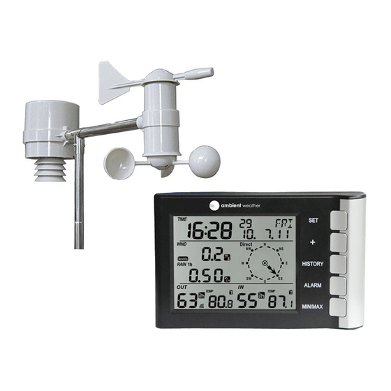
The WS-5300 weather station consists of a display console (receiver), a thermo-hygrometer rain gauge transmitter unit (transmitter), a wind direction sensor, a wind speed sensor, and mounting hardware. 3.1 Parts List The WS-5300 weather station consists of the following parts (as referenced in Figure 1 and Figure 2). Item Display Console Frame Dimensions (LxWxH): 5.5”... -
Page 3: Recommend Tools
Figure 1 Figure 2 3.2 Recommend Tools Precision screwdriver (for small Phillips screws) Compass or GPS (for wind direction calibration) Adjustable Wrench Version 1.3 ©Copyright 2013, Ambient LLC. All Rights Reserved. Page 3... -
Page 4: Sensor Assembly Set Up
3.3 Sensor Assembly Set Up 1. Insert batteries into the thermo-hygrometer / rain gauge transmitter. Locate the battery door on the thermo-hygrometer / rain gauge transmitter, as shown in Figure 3. Turn the set screw counter clockwise to loosen the screw, and rotate the sheet metal bracket to open the battery compartment. - Page 5 Pull out the battery compartment, as shown in Figure 4. Figure 4 Version 1.3 ©Copyright 2013, Ambient LLC. All Rights Reserved. Page 5...
- Page 6 Insert 2 x AA batteries in the battery compartment, as shown in Figure 5. Note: Do not install the batteries backwards. You can permanently damage the thermo-hygrometer. Do not use rechargeable batteries. Note: We recommend installing Lithium AA batteries: http://www.ambientweather.com/enaaliba4pa.html Lithium batteries provide longer life and operate in colder temperatures.
-
Page 7: Display Console
2. Attach the wind cups to the anemometer assembly (if necessary, some weather stations come pre-assembled). Push the wind cups into the anemometer shaft, as shown in Figure 6. Tighten the set screw with the Allen Wrench (included), as shown in Figure 6. Make sure the wind cups spin freely. - Page 8 Figure 7 1. Time alarm on icon 15. Indoor humidity 2. Daylight Savings Time (DST) icon 16. Rainfall units of measure 3. Radio Controlled Clock (RCC) icon for time 17. Outdoor temperature high alarm and low reception alarm 4. Date of the week/time zone 18.
-
Page 9: Initial Display Console Set Up
3.4.1 Initial Display Console Set Up Note: The sensor array must be powered and updating before powering up the console, or the console will time out searching for the sensors. Power the console last. Make certain the weather station sensor array is at least 10’ away from the console and within 100’ of the console. -
Page 10: Weather Station Installation
5. Radio interference such as PCs, radios or TV sets can, in the worst case, entirely cut off radio communication. Please take this into consideration when choosing console or mounting locations. 6. Visit Ambient Weather Mounting Solutions for assistance and ideas for mounting your weather station: http://www.ambientweather.com/amwemoso.html 4.3 Final Installation of Sensor Array... - Page 11 Figure 8 Fasten the mounting pole to your mounting pole or bracket (purchased separately) with the two U-bolts, mounting pole brackets and nuts, as shown in Figure 2. Tighten the mounting pole to your mounting pole with the U-Bolt assembly, as shown in Figure 9. Version 1.3 ©Copyright 2013, Ambient LLC.
-
Page 12: Console Operation
Figure 9 5. Console Operation Note: The display console has six buttons for basic operation: button, button, HISTORY button, button, and button. ALARM MIN/MAX There are five modes of operation: 1. Set Mode to program the display 2. Quick Set Mode to change general display settings 3. - Page 13 begin flashing (example, lcd0 thru lcd8). The lowest LCD contrast level 0 and the highest LCD contrast level is 8. Press the + button or button to adjust the contrast level from 0 to 8 (the default is MIN/MAX 2. Time Zone. Press the button to display the time zone.
-
Page 14: Quick Set Mode
change the hour setting. The RCC time will override the manual set time. 5. Set Minute. Press the button to set the minute. Press the + button or MIN/MAX button to change the minute setting. The RCC time will override the manual set time. 6. -
Page 15: Alarm Mode
begin flashing. Press the + button to alternate the display between outdoor temperature, dew point and wind chill. Press the button to exit the SET mode. 5.3 Alarm Mode 5.3.1 Setting Alarms To enter the Alarm mode from the normal mode, press (do not hold) the button. - Page 16 4. Set High Gust Alarm. Press the button again and the high gust speed alarm will begin flashing. Press the + button or button to change the gust alarm setting. MIN/MAX To set the gust alarm, press the button while the wind gust is flashing, and the alarm ALARM icon will turn on.
- Page 17 To set the outdoor humidity alarm, press the button while the outdoor humidity is ALARM flashing, and the alarm icon will turn on. To turn off the alarm, press the ALARM HI AL button again, and the alarm icon will turn off. When the outdoor humidity exceeds the alarm setting, the alarm will sound.
- Page 18 To set the indoor temperature alarm, press the button while the indoor temperature ALARM is flashing, and the alarm icon will turn on. To turn off the alarm, press the HI AL button again, and the alarm icon will turn off. ALARM When the outdoor temperature exceeds the alarm setting, the alarm will sound.
-
Page 19: Cancelling The Alarm While Sounding
6. Indoor Humidity Low Alarm. Press the button again and the indoor humidity alarm will begin flashing. Press the + button or button to change the indoor humidity MIN/MAX alarm setting. To set the indoor humidity alarm, press the button while the indoor humidity is ALARM flashing, and the alarm icon will turn on. -
Page 20: Min Mode
value is flashing, hold the button for three seconds to reset to the current value and current date and time. Press the + button to proceed to the next maximum value, as defined in Table 1. Maximum Parameter 1 Wind Speed 2 Wind Gust 3 1 Hour Rain 4 24 Hour Rain... -
Page 21: Calibration Procedure
5.5.2 Calibration Procedure To enter the calibration mode from the normal mode, press and hold the HISTORY button for eight seconds. The backlight turns on and the console beeps. The first calibration factor will being flashing. To exit the calibration mode, press the button again. -
Page 22: History Mode
to calibration. 3. Outdoor Humidity Calibration. Press the button again and the outdoor humidity value will begin flashing. Press the + button or button to adjust the humidity value to MIN/MAX the calibrated value. Discussion: Humidity is a difficult parameter to measure electronically and drifts over time due to contamination. -
Page 23: Reset Factory Default
-21 hours and -24 hours. Press the button again to exit the History Mode, or wait for the HISTORY 30-second time-out to take effect. To clear historical data, while in the History Mode, press the button and the CLEAR icon will begin flashing. -
Page 24: Power Consumption
Barometric Pressure 8.85 to 32.50 inHg ± 0.08 inHg (within 0.01 inHg range of 27.13 to 32.50 inHg) Rain 0 to 394 in. ± 10% 0.01 in Wind Direction 0 - 360 º 22.5º (16 point 22.5º (16 point compass) compass) Wind Speed 0 to 110 mph... -
Page 25: Thermo-Hygrometer Sensor Replacement
9.1 Thermo-Hygrometer Sensor Replacement 1. Reference Figure 10. Loosen the three recessed screws on the bottom of the thermo-hygrometer rain gauge assembly until there is little tension. Figure 10 Version 1.3 ©Copyright 2013, Ambient LLC. All Rights Reserved. Page 25... - Page 26 2. Pull the rain gauge funnel from the assembly as shown in Figure 11. Figure 11 Version 1.3 ©Copyright 2013, Ambient LLC. All Rights Reserved. Page 26...
- Page 27 3. Remove the sensor electronics door by removing four screws as shown in Figure 12. Figure 12 Version 1.3 ©Copyright 2013, Ambient LLC. All Rights Reserved. Page 27...
- Page 28 4. Remove the sensor wire from the guide, and with a small flathead screwdriver to provide force, pull the connector from the socket, as shown in Figure 13 (the block size in the image has been exaggerated for illustration purposes). You will need to work the connector back and forth and carefully pull out of the socket.
- Page 29 5. Unscrew the set screw from the rain gauge assembly, as shown in Figure 14. Free the connector wire from the side of the unit and gently pull off the thermo-hygrometer rain gauge assembly from the mounting pole. Do not twist, or you may damage the wire insulation. Figure 14 Version 1.3 ©Copyright 2013, Ambient LLC.
-
Page 30: Anemometer Sensor Replacement
9.2 Anemometer Sensor Replacement To replace the anemometer, you must perform all of the steps defined in Section 9.1. Next, remove the anemometer from the mounting bracket, as shown in Figure 15. Figure 15 10. Troubleshooting Guide If your question is not answered here, you can contact us as follows: 1. - Page 31 Problem Solution while in the search mode. 2. Install a fresh set of batteries in the remote sensor array. For cold weather environments, install lithium batteries. 3. The maximum line of sight communication range is 300’, 100’ under most conditions. Move the sensor assembly closer to the display console.
-
Page 32: Accessories
This precision screwdriver kit is a must for in 1 Pocket Precision assembling this weather station due to the Screwdriver small, precision screws. Ambient Weather Humidity Humidity calibration kits allow for accurate Calibration Kits calibration of the humidity sensors. Weather Station Mounting... -
Page 33: Warranty Information
Statement according to FCC part 15.21: Modifications not expressly approved by this company could void the user's authority to operate the equipment. Statement according to FCC part 15.105: NOTE: This equipment has been tested and found to comply with the limits for a Class B digital device, pursuant to Part 15 of the FCC Rules.
Need help?
Do you have a question about the WS-5300 and is the answer not in the manual?
Questions and answers