Table of Contents
Advertisement
Ambient Weather WS-2000 Wi-Fi OSPREY Solar Powered
Wireless Weather Station User Manual
Table of Contents
1.
Introduction ..................................................................................................................................... 2
2.
Warnings and Cautions ................................................................................................................... 2
3.
Quick Start Guide............................................................................................................................ 3
4.
Pre-Installation Checkout and Site Survey...................................................................................... 3
4.1
Pre Installation Checkout ........................................................................................................ 3
4.2
Site Survey .............................................................................................................................. 3
5.
Getting Started ................................................................................................................................ 4
5.1
Parts List ................................................................................................................................. 4
5.2
Recommend Tools ................................................................................................................... 4
5.3
Sensor Array Set Up ................................................................................................................ 5
5.3.1
Install Wind Vane ............................................................................................................... 5
5.3.2
Install Wind Cups ............................................................................................................... 6
5.3.3
Install U-Bolts .................................................................................................................... 6
5.3.4
Install the Rain Gauge Funnel ............................................................................................ 7
5.3.5
Install Batteries................................................................................................................... 8
5.3.6
Install Mounting Pole ......................................................................................................... 9
5.5 Best Practices for Wireless Communication ................................................................................. 9
5.6
Indoor-Outdoor Thermo-Hygrometer-Barometer Transmitter .............................................. 10
5.7
Indoor/Outdoor Thermo-Hygrometer, 8 Channel (optional) ................................................. 11
5.8
PM2.5 Air Quality Sensor ..................................................................................................... 13
5.9
Sensor Placement .................................................................................................................. 14
5.10
Best Practices for Wireless Communication ......................................................................... 14
5.11
Display Tablet ....................................................................................................................... 15
6.
Display Tablet Operation .............................................................................................................. 16
6.1
Initial Display Tablet Operation ............................................................................................ 16
6.2
Home Screen Display ............................................................................................................ 17
6.3
Display Buttons ..................................................................................................................... 18
6.4
Multi-Chanel and Scroll Mode for Optional Sensors ............................................................ 19
6.5
Other Console Features ......................................................................................................... 19
6.5.1
Weather Forecasting ......................................................................................................... 19
6.5.2
Wireless Signal Quality Icon ............................................................................................ 20
6.5.3
Weather Forecasting Description and Limitations ........................................................... 20
6.5.4
Lightning Icon .................................................................................................................. 21
6.5.5
PM2.5 Sensor (optional) .................................................................................................. 21
6.6
History Mode ........................................................................................................................ 21
6.6.1
Min/Max ........................................................................................................................... 21
6.6.2
Archive Memory Mode .................................................................................................... 22
6.6.3
Graph ................................................................................................................................ 25
6.7
Set Mode ............................................................................................................................... 26
6.7.1
Set Date and Time ............................................................................................................ 27
6.7.2
Set Time Format ............................................................................................................... 29
6.7.3
Set Date Format................................................................................................................ 29
6.7.4
Temperature Units of Measure ......................................................................................... 29
Version 2.12
©Copyright 2020, Ambient LLC. All Rights Reserved.
Page 1
Advertisement
Table of Contents

Related Manuals for Ambient Weather WS-2000


Summary of Contents for Ambient Weather WS-2000
-
Page 1: Table Of Contents
Ambient Weather WS-2000 Wi-Fi OSPREY Solar Powered Wireless Weather Station User Manual Table of Contents Introduction ............................. 2 Warnings and Cautions ........................2 Quick Start Guide..........................3 Pre-Installation Checkout and Site Survey..................3 Pre Installation Checkout ......................3 Site Survey ..........................3 Getting Started .......................... -
Page 2: Introduction
California Prop 65 ........................66 1. Introduction Thank you for your purchase of the Ambient Weather WS-2000 Wi-Fi OSPREY Solar Powered Wireless Weather Station. The following user guide provides step by step instructions for installation, operation and troubleshooting. To download the latest manual and additional troubleshooting tips, please visit: https://help.ambientweather.net/product/ws-2000/... -
Page 3: Quick Start Guide
home. Warning: Installing your weather station in a high location may result in injury or death. Perform as much of the initial check out and operation on the ground and inside a building or home. Only install the weather station on a clear, dry, day. 3. -
Page 4: Getting Started
8. Visit Ambient Weather Mounting Solutions for assistance and ideas for mounting your weather station: https://help.ambientweather.net/help/weather-station-mounting-solutions/ 5. Getting Started The Ambient Weather WS-2000 OSPREY Wi-Fi Personal Weather Station consists of an indoor display tablet (receiver + Wi-Fi transmitter) and an all-in-one outdoor weather sensor array. 5.1 Parts List Item... -
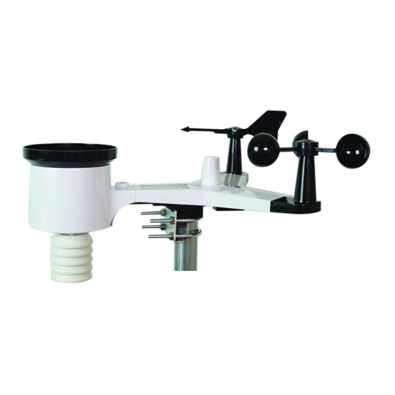
Page 5: Sensor Array Set Up
5.3 Sensor Array Set Up Figure 1 Description Description Wind Vane (measures wind direction) Solar panel Wind Speed Sensor (measures wind speed) U-Bolt UV sensor/ Light sensor Battery compartment Thermometer-hygrometer sensor (measures Reset button temperature and humidity) Rain collector LED transmitter Indicator Bubble level 5.3.1 Install Wind Vane Reference Figure 2. -
Page 6: Install Wind Cups
Figure 2 5.3.2 Install Wind Cups Reference Figure 3. (a) push the wind cups on to the shaft. (b) tighten the set screw with a precision screwdriver and make sure the wind cups spin freely. Note: You may need to back out the set screw first before sliding the cups onto the shaft. Figure 3 5.3.3 Install U-Bolts Note: Your U-bolts may have come preassembled at the factory. -
Page 7: Install The Rain Gauge Funnel
Figure 4 5.3.4 Install the Rain Gauge Funnel Reference Figure 5. Install the rain gauge funnel. Rotate clockwise to attach the funnel to the sensor array. Version 2.12 ©Copyright 2020, Ambient LLC. All Rights Reserved. Page 7... -
Page 8: Install Batteries
Figure 5 5.3.5 Install Batteries Reference Figure 6. Insert 2 x AA non-rechargeable batteries (not included) into the battery compartment. The LED indicator on the back of the transmitter will turn on for four seconds, and then flash once every 16 seconds (the sensor transmission update period). Figure 6 Note: If the LED does not light up, or stays on permanently, make sure the battery polarity is correct, or the batteries are fresh. -
Page 9: Install Mounting Pole
5.3.6 Install Mounting Pole Reference Figure 7. The mounting assembly includes two U-Bolts and a bracket that tightens around a 1 to 2” diameter pole (not included) using the four U-Bolt nuts. Figure 7 Use the bubble level next to the rain sensor to make sure the sensor array is completely level. If the sensor array is not level, the rain gauge, UV and solar radiation sensors will not measure properly. -
Page 10: Indoor-Outdoor Thermo-Hygrometer-Barometer Transmitter
siding. If you have metal siding, align the remote and tablet through a window to get a clear line of sight. The following is a table of reception loss vs. the transmission medium. Each “wall” or obstruction decreases the transmission range by the factor shown below. Medium RF Signal Strength Reduction Glass (untreated) -
Page 11: Indoor/Outdoor Thermo-Hygrometer, 8 Channel (Optional)
Figure 9 5.7 Indoor/Outdoor Thermo-Hygrometer, 8 Channel (optional) The WS-2000 supports up to 8 additional thermo-hygrometer sensors ( WH31) , which can be viewed on the display tablet and Internet. Note: Do not use rechargeable batteries. We recommend fresh alkaline batteries for outdoor temperature ranges between -4 °F and 140 °F and fresh lithium batteries for outdoor temperature... - Page 12 2. BEFORE inserting the batteries, locate the dip switches on the inside cover of the lid of the transmitter. 3. Channel Number: The WS-2000 supports up to eight transmitters. To set each channel number (the default is Channel 1), change Dip Switches 1, 2 and 3, as referenced in Figure 4.
-
Page 13: Pm2.5 Air Quality Sensor
7. Close the battery door. 8. Repeat for the additional remote transmitters, verifying each remote is on a different channel. 5.8 PM2.5 Air Quality Sensor The WS-2000 supports one indoor and one outdoor PM2.5 Air Quality sensor. For more information, please visit: https://help.ambientweather.net/product/pm25 Version 2.12... -
Page 14: Sensor Placement
5.9 Sensor Placement It is recommended you mount the remote sensor outside on a north facing wall, in a shaded area, at a height at or above the receiver. If a north facing wall is not possible, choose a shaded area, under an eve. -
Page 15: Display Tablet
Wood 10-40% Brick 10-40% Concrete 40-80% Metal 90-100% 5.11 Display Tablet Figure 15 Connect the display tablet power jack to AC power with the power adapter (included), as shown in Figure 16. Place the sensor array and indoor thermo-hygrometer transmitter about 5 to 10 feet from the display tablet and wait several minutes for the remote sensors to synchronize with the display tablet. -
Page 16: Display Tablet Operation
Description Memory card slot for upgrades and backup data USB port for loading the operating system (not required by user) Power jack Reset Figure 16 6. Display Tablet Operation Note: About This Section. The display tablet includes buttons at the bottom with icons signifying the menu functions. -
Page 17: Home Screen Display
Figure 17 6.2 Home Screen Display The display tablet home screen layout is shown in Figure 18. Figure 18 Version 2.12 ©Copyright 2020, Ambient LLC. All Rights Reserved. Page 17... -
Page 18: Display Buttons
Description Description WeatherUnderground.com connection Channel indicator icon AmbientWeather.net connection icon Rain rate, daily, hourly, weekly, monthly and yearly rain Wi-Fi signal strength icon. Forecast icon based on rate of change of pressure An exclamation point ! indicates the display is connected to Wi-Fi but not the Internet. -
Page 19: Multi-Chanel And Scroll Mode For Optional Sensors
Icon Description Brightness control key Press this key to decrease the brightness Backlight on/off key Press this key to turn on/off the display Background key Press this key to choose between dark background display and light background display Pressure display key Press this key to choose the display between Absolute pressure and Relative pressure. -
Page 20: Wireless Signal Quality Icon
The forecast icon is based on the rate of change of barometric pressure. Please allow at least one month for the weather station to learn the barometric pressure over time. Sunny Partly Cloudy Cloudy Rainy Stormy Pressure Pressure increases Pressure decreases Pressure decreases Pressure rapidly... -
Page 21: Lightning Icon
6.5.5 PM2.5 Sensor (optional) An optional PM2.5 sensor is available for the WS-2000. The display shows the current PM2.5 measurement, and the 24-hour running average, which is a better indication of the accumulative effect of particulates on overall health. -
Page 22: Archive Memory Mode
Figure 22 or down button to scroll to the parameter you wish to clear. Press the Press the up button to check the parameter you wish to clear. Once checked, press the Enter Key To confirm the selection, press . The high and low will be reset for the checked parameters. - Page 23 Figure 23 Clear All Recall scroll scroll scroll up scroll Switch to return History page left right down graph home screen To clear all the records, press the Clear All History button and you will be prompted to clear the data. Press the down arrow once to confirm .
- Page 24 Figure 24 To scroll to a specific page, press the Recall Page button Press the left https://ambientweather.net/help/does-not-update-ambientweather-net-osprey-series/ or right button to select a digit in the page number, press Plus or Minus button to change the number up or down. Press to change the activated option field, toggle OK or Cancel then press key to confirm.
-
Page 25: Graph
Figure 25 6.6.3 Graph Graph memory for all parameters, based on the date and time. Version 2.12 ©Copyright 2020, Ambient LLC. All Rights Reserved. Page 25... -
Page 26: Set Mode
Figure 26 Change x-axis time Change graph Switch to Min/Max return home display between 12, 24, 48 and parameters 72 hours. 6.7 Set Mode The Set Mode allows you to customize your display, manage archive data, and connect your display tablet to the Internet. -
Page 27: Set Date And Time
Enter the Setup Mode Figure 27 Select units Select units Select Select Scroll field Scroll Select return to of measure of measure value value field next Set home scroll scroll down Page value up value down 6.7.1 Set Date and Time Set the date and time. - Page 28 2. Set Date. (month:day:year) Press to set the date. The month field will turn red. Press to select month, day or year. Press to increase or decrease the value. 3. Set Time Zone. Press to set the time zone. Press to increase the time zone to decrease the time zone.
-
Page 29: Set Time Format
6.7.2 Set Time Format Press to change the time format between hour:minute:second (h:mm:ss), AM hour:minute:second (AM h:mm:ss) and hour:minute:second AM (h:mm:ss AM). 6.7.3 Set Date Format Press to change the date format between MM-DD-YYY, DD-MM-YYYY and YYYY-MM-DD. 6.7.4 Temperature Units of Measure Press to change the temperature units of measure between °F and °C. -
Page 30: Rainfall Units Of Measure
6.7.7 Rainfall Units of Measure Press to change the rainfall units of measure between in and mm. 6.7.8 Solar Radiation Units of Measure Press to change the solar radiation units of measure between W/m^2, lux and fc. 6.7.9 Multi-Channel Sensor Press to view, check the status, re-register and modify the name of optional sensor channels 1-8. -
Page 31: Backlight Display
Figure 29 To edit the channel name, press key to select the channel name. The name field will turn green. Press the key to view the keyboard and enter the sensor name. Press to scroll to the character and press to select the character. -
Page 32: Longitude And Latitude
Figure 31 adjust up or adjust down scroll left scroll right scroll up scroll down return home check or uncheck 6.7.11 Longitude and Latitude x 11 k ey to Set longitude and latitude for your location. This calculation is used for Press the Plus the sunrise and sunset calculation. - Page 33 hemisphere setting is WEST. To change to EAST, press the key. Press to change your longitude. The longitude x 100 will turn red. Press to increase or decrease the value. Press to change the remaining longitude variables. Figure 32 To determine your longitude and latitude, we recommend the following website: www.bing.com/maps Reference Figure 33 below: 1.
-
Page 34: Barometer Display
3. In this example, the location entered into the display is as follows: Latitude = 33.30 North Longitude = 111.96 West after rounding to two significant digits. Record your longitude and latitude here for future reference: Longitude: Latitude: Figure 33 6.7.12 Barometer Display x 12 Press... -
Page 35: Rainfall Season
Thus, your absolute pressure may read 28.62 inHg (969 mb) at an altitude of 1000 feet (305 m), but the relative pressure is 30.00 inHg (1016 mb). The standard sea-level pressure is 29.92 in Hg (1013 mb). This is the average sea-level pressure around the world. - Page 36 Figure 34 Select Keyboard Scroll field up Scroll field down return to Setup 1. Set Station ID. Press to highlight the Station ID. Enter your station ID obtained from Wunderground.com. Press to display the keyboard. Press to scroll to the character and press to select the character.
- Page 37 Figure 35 6.7.15.1 Registering on Wunderground.com Note: The Weather Underground website is subject to change. 1. Visit Wunderground.com, and select the Join link in the upper right and corner and create a Free Account. 2. From the menu, Select More | Add a Weather Station, or visit: https://www.wunderground.com/member/devices/new 3.
- Page 38 Note: Your station ID will have the form: KSSCCCC###, where K is for USA station (I for international), SS is your state, CCCC is your city and ### is the station number in that city. In the example above, KAZPHOEN424 is in the USA (K), State of Arizona (AZ), City of Phoenix (PHOEN) and #424.
- Page 39 AmbientWeather.net. Enable the skill and get started: say "Alexa, ask Ambient Weather for a weather report.". This will provide you with your outdoor weather report, but you can ask for your indoor weather report as well by saying, "Alexa, ask Ambient Weather about the indoor conditions."...
-
Page 40: Wifi Scan
AmbientWeather.net Link your account to get started: say 'hey google, Ambient Weather... weather report.' This will provide you with your outdoor weather report. You can ask for your indoor weather report as well by saying, ' indoor conditions'. - Page 41 scan. If the problem persists, power down and up your display tablet and perform another Wi-Fil scan. If you are uploading to Wunderground.com successfully, the icon will show on the left top of the display tablet. If you are uploading to AmbientWeather.net successfully, the icon will show on the left top of the display tablet.
- Page 42 3). Press to highlight the Password. Press to display the keyboard and start to enter your password. Press to scroll to the character and press enter the character. Press to return to the setup page. 4).Press to highlight the OK button to connect. After connecting successfully, the status will display Connected.
-
Page 43: Background
Figure 42 6.7.17 Background x 17 Press Plus to toggle between Light Mode and Dark Mode. 6.7.18 More x 18 Press Plus to view additional settings. Note: You must be running Firmware Version 1.5.3 or greater. Version 2.12 ©Copyright 2020, Ambient LLC. All Rights Reserved. Page 43... -
Page 44: Soil Moisture Calibration
Select field Scroll field up Scroll field down return to Setup Figure 43 6.7.19 Soil Moisture Calibration The soil moisture sensor provides for optional two-point linear calibration. This is important due to different soil types and density. The calibration equation is defined as: % Soil Moisture (calibrated) = (Now AD –... -
Page 45: Multi-Channel Temperature And Humidity Calibration
place the soil sensor in the medium and allow the sensor to stabilize for one hour. Next, set the 100%AD calibration set point to the Now AD value. 6.7.19.3 Customize and Reset Once the 0%AD and 100%AD are entered, set Customize to ON. To return to the non-calibrated settings, set Customize to OFF. - Page 46 Increase Decrease Select Select Scroll field Scroll field return value value value value down home Figure 45 The calibrated temperature and humidity equations are as follows: Calibrated Temperature = Measured Temperature + Temp. Offset Calibrated Humidity = Measured Humidity + Humidity. Offset To adjust the parameter, press to scroll to the parameter you wish to change.
-
Page 47: Pm2.5 Air Quality Sensor Calibration
The console supports multiple sensors and sensor arrays. You can disable or enable specific sensors. To view a complete list of sensor IDs, visit: https://help.ambientweather.net/help/sensor-abbreviations-for-ws-2000-c-display-console/ For the WS-2000 weather station, the following sensor IDs are assigned: WH65: Sensor array Version 2.12 ©Copyright 2020, Ambient LLC. - Page 48 WH32B: Indoor thermo-hygrometer-barometer Select field Scroll field up Scroll field down return to Setup Figure 47 button to edit and save settings. To register, disable or select a specific sensor, press the Version 2.12 ©Copyright 2020, Ambient LLC. All Rights Reserved. Page 48...
- Page 49 Figure 48 Figure 49 Version 2.12 ©Copyright 2020, Ambient LLC. All Rights Reserved. Page 49...
-
Page 50: Alarm Mode
6.8 Alarm Mode Press to Enter the Alarm Mode The upper alarm is displayed on the right and the lower alarm is displayed on the left. If the measured value is greater than the maximum alarm setting, the alarm will sound. If the measured value is less than the minimum alarm setting, the alarm will sound. -
Page 51: Calibration Mode
Figure 50 Increase Decrease Select Select Scroll field Scroll Enter return alarm limit alarm limit value value field sub-setup to home values values down mode 6.9 Calibration Mode For multi-channel soil moisture, temperature and humidity, and PM2.5 sensor calibration, refer to Section 6.7.18. - Page 52 Figure 51 Increase Decrease Select Select Scroll field Scroll Enter return calibrated calibrated value value field sub-setup to home value value down mode To adjust the parameter, press to scroll to the parameter you wish to change. Press highlight the sign (positive vs. negative, if applicable) and significant digit. Press to change the calibrated value.
- Page 53 Parameter Type of Default Typical Calibration Source Calibration Temperature Offset Current Value Red Spirit or Mercury Thermometer (1) Humidity Offset Current Value Sling Psychrometer (2) Offset Current Value Calibrated laboratory grade Barometer barometer REL Barometer Offset Current Value Local airport (3) Wind Direction Offset Current Value GPS, Compass (4)
- Page 54 Without a calibrated source, wind speed can be difficult to measure. We recommend using a calibrated wind meter (available from Ambient Weather) and a constant speed, high speed fan. (7) The rain collector is calibrated at the factory based on the funnel diameter. The bucket tips every 0.01”...
-
Page 55: Factory And Data Export
Note: The purpose of calibration is to fine tune or correct for any sensor error associated with the devices margin of error. Errors can occur due to electronic variation (example, the temperature sensor is a resistive thermal device or RTD, the humidity sensor is a capacitance device), mechanical variation, or degradation (wearing of moving parts, contamination of sensors). - Page 56 1. Re-register Transmitter Indoor. Re-synchronizes the wireless signal from the indoor thermo-hygrometer-barometer. Press to highlight this field. Press key to select re-register indoor transmitter. Press Message Box” Are key to popup the you sure you want to register the new indoor transmitter?”...
-
Page 57: Exporting Data File Format (Data Logging)
sure you want to reset to factory default?” Press to select Yes or No. Press key to confirm the selection. 6. Backup data. Backup data to micro SD / TF card (see the Accessories section of this manual for more information on micro SD / TF cards). Insert the micro SD / TF Card into the slot, as shown in Figure 16. -
Page 58: Exporting Channel 1-8 Data
The format of the data is csv (comma separated value) and can be opened in a spreadsheet program such as Microsoft Excel for advanced data analysis, with the following headers: Column Parameter 1 No (data point number) 2 Time 3 Indoor Temperature (°F) 4 Indoor Humidity (%) 5 Outdoor Temperature (°F) 6 Outdoor Humidity (%) -
Page 59: Glossary Of Terms
Figure 55 7. Glossary of Terms Term Definition Absolute Barometric Absolute pressure is the measured atmospheric pressure and is a Pressure function of altitude, and to a lesser extent, changes in weather conditions. Absolute pressure is not corrected to sea-level conditions. Refer to Relative Barometric Pressure. - Page 60 Term Definition relative humidity will decrease. Feels Like The Feels Like temperature is a combination of Heat Index when it is hot outside, and Wind Chill when it is cold outside. Wind Chill temperature is defined by the National Weather Service for temperatures at or below 40 °F and wind speeds above 5.0 mph.
-
Page 61: Specifications
8. Specifications 8.1 Wireless Specifications • Line of sight wireless sensor array RF transmission (in open air): 330 feet, 100 feet under most conditions • Line of sight Wi-Fi RF transmission (in open air): 80 feet • Update Rate: Outdoor Sensor: 16 seconds, Indoor Sensor: 64 seconds •... -
Page 62: Troubleshooting Guide
5. In snowy environments, spray the top of the weather station with anti-icing silicon spray to prevent snow build up. 10. Troubleshooting Guide If your question is not answered here, you can contact us as follows: 1. Online Support: https://ambientweather.net/product/ws-2000 2. Email Support: support@ambientweather.com 3. Technical Support: 480-346-3380 (M-F 8am to 4pm Arizona Time) Problem... - Page 63 5. The tablet does not support guest networks. Exclamation point ! If there is an exclamation point ! next to the Wi-Fi icon on the WS-2000 next to the Wi-Fi icon display, it means the display is connected to Wi-Fi but the Wi-Fi is not Version 2.12...
-
Page 64: Accessories
The following software and hardware accessories are available for this weather station at www.AmbientWeather.com Accessory Description Ambient Weather Mounting Ambient Weather provides the most comprehensive mounting solutions Solutions for weather stations, including tripods, pole extensions, pole mounting kits, ground stakes and more. WS-2000-C Add as many display tablets as you like to your weather station. -
Page 65: Warranty Information
1. This device may not cause harmful interference. 2. This device must accept any interference received, including interference that may cause undesired operation. Statement according to FCC part 15.21: Modifications not expressly approved by this company could void the user's authority to operate the equipment. -
Page 66: California Prop 65
15. California Prop 65 WARNING: Use of the Ambient Weather Products can expose you to chemicals, including lead and lead compounds, which are known to the State of California to cause cancer and bisphenol A (BPA), and phthalates DINP and/or DEHP, which are known to the State of California to cause birth defects or other reproductive harm. - Page 67 For further information about California's Proposition 65, please visit https://oehha.ca.gov/prop65/background/p65plain.html Version 2.12 ©Copyright 2020, Ambient LLC. All Rights Reserved. Page 67...
Need help?
Do you have a question about the WS-2000 and is the answer not in the manual?
Questions and answers
Which button on the console is the LIGHT/SNOOZE button?
@Bruce Jeralds My ambient weather display went suddenly black. We changed the batteries in the weather station but the display stays black.
When plugging in WS-2000 it just beeps with "Starting" flashing on screen.
The Ambient Weather WS-2000 beeps and displays "Starting" when plugged in due to a possible issue with the boot process. This can be caused by a corrupted bootloader, a failed firmware flash, or an inadequate power supply that drops voltage under load. If resetting the device and replacing the internal battery do not fix it, the display unit or internal components may be damaged.
This answer is automatically generated
how do you delete a sensor
To delete a sensor on the Ambient Weather WS-2000, you need to re-register the outdoor transmitter. This process removes the previous sensor registration. Follow these steps:
1. Highlight the "Re-register Transmitter Outdoor" field.
2. Press the select key to open the message box: "Are you sure you want to register the new outdoor transmitter?"
3. Select "Yes" to confirm.
This action will remove the previous sensor and allow a new one to be registered.
This answer is automatically generated
Ws 2000 display not connected to weather underground or ambient weather networks. I can’t get any assistance from weather underground. Can you help me?
If the Ambient Weather WS-2000 display is not connecting to Weather Underground or Ambient Weather networks, follow these steps:
1. Check Wi-Fi Connection: Ensure the display is connected to a 2.4 GHz Wi-Fi network. The WS-2000 does not support guest networks.
2. Look for Exclamation Mark (!): If an exclamation mark appears next to the Wi-Fi icon, the display is connected to Wi-Fi but not to the Internet.
3. Confirm Internet Access: Make sure your router’s 2.4 GHz band is connected to the Internet.
4. Reboot Router: If the issue persists, restart your router.
5. Verify Firmware: Check if the Wi-Fi firmware is updated using the awnet app. If the WS-2000 is not listed in the app, this step may not be possible.
6. Factory Reset: If other steps fail, perform a factory reset on the console and re-enter your Wi-Fi credentials after disabling the 5 GHz band.
These steps should help resolve the connection issue.
This answer is automatically generated
How do I set up the sunrise/sunset graphic on the WS-2000?