Table of Contents
Advertisement
Ambient Weather WS-50-C Wi-Fi Smart Weather Station User
Table of Contents
Contents
................................................................................................................................................ 3
1.
.................................................................................................................................................... 4
2.
3.
4.
........................................................................................................................................................... 4
4.1
4.2
4.3
5.
5.1
5.2
5.3
6.
7.
7.1
7.1.1
7.1.2
...................................................................................................................................... 12
7.2
7.2.1
7.2.2
7.3
7.3.1
7.3.2
7.4
7.4.1
7.4.2
7.5
7.5.1
7.5.2
7.5.3
7.5.4
Version 1.4
....................................................................................................................................... 4
........................................................................................................ 4
...................................................................................................................... 5
........................................................................................................................ 6
............................................................................................................. 8
................................................................................................................ 8
...................................................................................................................................... 8
................................................................................................................ 9
...................................................................................................................................... 9
.................................................................................................................. 9
.............................................................................................................. 10
.................................................................................................................. 12
................................................................................................................ 13
........................................................................................................ 14
.................................................................................................... 14
.................................................................................................. 16
......................................................................................................................... 22
........................................................................................................ 23
.................................................................................................... 24
.................................................................................................. 26
..................................................................................................... 26
............................................................................................................................. 27
©Copyright 2020, Ambient LLC. All Rights Reserved.
Manual
......................................................................................... 7
......................................................................... 7
........................................................................ 17
................................................................... 17
Page 1
Advertisement
Table of Contents

Related Manuals for Ambient Weather WS-50-C


Summary of Contents for Ambient Weather WS-50-C
-
Page 1: Table Of Contents
Ambient Weather WS-50-C Wi-Fi Smart Weather Station User Manual Table of Contents Contents ..............................3 Introduction ..............................4 Warnings ............................4 Quick Start Guide Parts ................................4 ......................4 WiFi Display Console (included) ........................5 Anemometer (optional) Rain Gauge (optional) ........................ - Page 2 Connect your Device to the Console's WiFi ..................52 ..................... 54 11.2 Accessing the Console's Web Interface ..........................57 AmbientWeather.net ....................57 12.1 Registering with AmbientWeather.net ........................58 12.2 Ambient Weather Apps Version 1.4 ©Copyright 2020, Ambient LLC. All Rights Reserved. Page 2...
-
Page 3: Introduction
The WS-50-C is a Wi-Fi connected device that receives sensor data from a variety of sensors, displays and configures this data, and sends it to your Wi-Fi router and the Internet. -
Page 4: Warnings
Connect the console to Wi-Fi Register at AmbientWeather.net Parts Wi-Fi Display Console (included) Item Image WS-50-C Display Console with Wi-Fi Frame Dimensions (LxHxW): 6 x 3.25 x 1 LCD Dimensions (LxW): 4.5 x 2.5" Version 1.4 ©Copyright 2020, Ambient LLC. All Rights Reserved. -
Page 5: Anemometer (Optional)
Item Image Power Adapter User Manual Figure 2 Anemometer (optional) Item Image WS-12-ANEMOMETER Dimensions: 3 ¼ x 6 x 8 ½” Pole Dimensions: 12 x 1½ x 1” Pole Mounting Bracket (with pole insert) Dimensions: 3 x 4 x 1 ½” Anemometer Mounting Bracket Back Plate (pole mount) Dimensions: 3 x 3 x 1”... -
Page 6: Rain Gauge (Optional)
Item Image Tapping screws Pole mounting nuts (M3) / bolts (∅3) Figure 3 Rain Gauge (optional) Item Image WS-12-RAIN Rain Gauge Dimensions: 8 1/4" x 7 3/4" x 5" (5" diameter) Rain Gauge Filter Dimensions: 2.48 x 2.48 x 1.1in Pole mounting U-bolt / nuts (M5) Figure 4 If sold separate from the anemometer (only one pole assembly is required per system), the following... -
Page 7: Indoor / Outdoor Thermo-Hygrometer (Optional)
Item Image Pole Mounting Bracket (with pole insert) Dimensions: 3 x 4 x 1 ½” Anemometer Mounting Bracket Back Plate (pole mount) Dimensions: 3 x 3 x 1” Pole mounting nuts (M5) / bolts (∅5) Tapping screws Pole mounting nuts (M3) / bolts (∅3) Figure 5 Indoor / Outdoor Thermo-Hygrometer (optional) Item... -
Page 8: Temperature Probe (Optional)
Item Image F007PF Floating Pool, Spa and Pond Thermometer Dimensions (LxWxH): 8.5" x 4.2" x 3.7" Figure 7 Temperature Probe (optional) Item Image F007TP Temperature Probe Dimensions (LxHxW): 4.5 x 2.0 x 0.75in Probe Length: 6 feet Figure 8 Indoor Thermo-Hygrometer Item Image FT012TH... -
Page 9: Sensor Assembly And Installation
Hammer and nail for hanging remote thermo-hygrometer transmitter. Sensor Assembly and Installation Anemometer Anemometer Assembly The anemometer assembly consists of the wind cups, wind vane, solar panel, bubble level, sensor mounting bracket and mounting foot. The solar panel provides power to the anemometer when the sun is out, and the batteries provide power at night (the solar panel does not charge the batteries). -
Page 10: Anemometer Installation
Figure 11 Insert four batteries into the battery compartment, then press the reset button, as shown in Figure 12. Note: Use high quality alkaline batteries, which have an operational temperature range of -4 to 140 °F. Use Energizer e2 Lithium batteries for low temperature installation, which have an operational temperature range of -40 to 140 °F. - Page 11 Figure 13 Fasten the wind transmitter to mounting pole brackets with foot-mounting, two ∅3 bolts and M3 nuts, as shown in Figure 14. Figure 14 Tighten the included mounting pole to your mounting pole (purchased separately) with the four ∅5 Bolts and M5 Nuts assembly, or fix on the wall with four tapping screws, as shown in Figure 15.
-
Page 12: Rain Gauge
Figure 15 Rain Gauge Rain Gauge Assembly The rain gauge consists of the rain gauge funnel, base, and drawer filter, as shown in Figure 16. Figure 16 Version 1.4 ©Copyright 2020, Ambient LLC. All Rights Reserved. Page 12... -
Page 13: Rain Gauge Installation
Rotate and detach the rain gauge funnel, as shown in Figure 17. Figure 17 Locate the battery door on the rain gauge transmitter, pull out the battery compartment, as shown in Figure Figure 18 Rain Gauge Installation Remove the rain gauge funnel from the base prior to installation by rotating the counterclockwise until the tabs on the base and the funnel align, then pulling upwards. -
Page 14: Thermo-Hygrometer (F007Th)
Figure 20 Thermo-Hygrometer (F007TH) Thermo-Hygrometer Assembly Remove the battery door on the back of the sensor by removing the set screw, as shown in Figure 21. Figure 21 BEFORE inserting the batteries, locate the dip switches on the inside cover of the lid of the Version 1.4 ©Copyright 2020, Ambient LLC. - Page 15 transmitter. Figure 22 displays all four switches in the OFF position (factory default setting). Figure 22 Channel Number: The WS-50 supports up to eight transmitters. To set each channel number (the default is Channel 1), change Dip Switches 1, 2 and 3, as referenced in Table 1. Temperature Units of Measure: To change the transmitter display units of measure (°F vs.
-
Page 16: Thermo-Hygrometer Installation
Figure 23 temperature (2) temperature units ( °F vs. °C) (3) channel number (4) relative humidity Close the battery door. Make sure the gasket (around the battery compartment) is properly seated in its trace prior to closing the door. Tighten the set screw. Thermo-Hygrometer Installation Note: If you place the sensor outside, it is recommended you mount it in a shaded area. -
Page 17: Floating Pool, Spa And Pond Thermometer (F007Pf)
(and cooling) of the walls and structure around it. This is known as thermal mass and has a time averaging affect (just like the temperature of your pool will respond faster than a lake). Optional Sensor Radiation Shields (Item SRS100LX) are available from Ambient Weather for mounting the sensor in an open area. - Page 18 To insert the batteries,, (1) Twist the BUTTON lid to unlock, (2) remove the button, and (3) twist the main body of the sensor by removing the lid, as shown in Figure 27 . IMPORTANT NOTE: Turn the lid counter clockwise to open, like the lid of a jar. Turning the lid clockwise may overtighten the lid.
- Page 19 inserting the batteries, locate the dip switches on the inside cover of the lid of the transmitter. Figure 29 displays all four switches in the OFF position (factory default setting). NOTE: The second-generation pool float includes a reset button. If the display does not power up after inserting the batteries, press the reset button shown in Figure 29. If your pool float does not include a reset button, cover the solar panel with one hand, remove the batteries, wait 60 seconds, reinsert the batteries, and uncover the solar panel.
- Page 20 DIP SWITCH FUNCTION DOWN DOWN DOWN Channel 1 (pool) DOWN DOWN Channel 2 (SPA) DOWN DOWN Channel 3 (optional) DOWN Channel 4 (optional) DOWN DOWN Channel 5 (optional) DOWN Channel 6 (optional) DOWN Channel 7 (optional) Channel 8 (optional) DOWN °F °C Table 2...
- Page 21 After inserting the batteries, the remote sensor LED indicator will light for 4 seconds, and then flash once per 60 seconds thereafter. Each time it flashes, the sensor is transmitting data. Verify the correct channel number (CH) and temperature units of measure (°F vs. °C) are on the display, as shown in Figure 23.
-
Page 22: Sensor Placement
To close the lid, (1) Twist the lid until it is firmly locked, and the button is aligned. (2) Insert the button and turn 90 degrees to lock the lid, as shown in Figure 34. Figure 34 A tether can be added into the button as shown in Figure 35. Figure 35 Place the sensor in the water and make sure that it is within the effective transmission range from the display console. -
Page 23: Probed Thermometer (F007Tp)
Place the sensor in the pool or spa within 100 feet of the display console (Figure 36, reference A). Avoid transmitting through solid earth or ground (Figure 36, reference B). Use a tether (string) to fix the sensor in the pool or spa. Place the console at least three feet away from computers, TVs, and wireless phones. -
Page 24: Probed Thermometer Assembly
Probed Thermometer Assembly Note: Do not use rechargeable batteries. They have a lower operating voltage and discharge faster than non-rechargeable batteries and will result in short transmission ranges. We recommend fresh alkaline batteries for temperature ranges between -4 °F and 140 °F and fresh lithium batteries for temperature ranges between -40 °F and 140 °F. - Page 25 DIP SWITCH FUNCTION DOWN DOWN DOWN Channel 1 DOWN DOWN Channel 2 DOWN DOWN Channel 3 DOWN Channel 4 DOWN DOWN Channel 5 DOWN Channel 6 DOWN Channel 7 Channel 8 DOWN °F °C Table 3 Insert two AAA batteries. After inserting the batteries, the remote sensor LED indicator will light for 4 seconds, and then flash once per 60 seconds thereafter.
-
Page 26: Probed Thermometer Installation
Probed Thermometer Installation The remote probe sensors have many applications, including measuring inside/outside air temperature, water temperature, soil or ground temperature and refrigerator / freezer temperatures. Refrigerator/Freezer Mounting The sensor includes a detachable suction cup that may be used to secure the remote sensor to the interior or exterior surface of the refrigerator/freezer, as shown in Figure 40. -
Page 27: Wall Mounting
Figure 41 Note: The sensors have the capability of being placed inside or outside the refrigerator/freezer, but it is recommended you install it outside. This will extend the battery life, the sensor life, and improve wireless communication range. Note: Make sure that the refrigerator surface is smooth and clean, so that suction cups will not fall off. -
Page 28: Indoor Thermo-Hygrometer (Ft012Th)
Figure 42 Indoor Thermo-Hygrometer (FT012TH) Indoor Thermo-Hygrometer Assembly Remove the battery door on the back of the sensor, as shown in Figure 1. Insert two AAA (alkaline or lithium, avoid rechargeable) batteries in the back of the indoor sensor. We do not recommend rechargeable batteries because they start at a lower voltage and do not last as long, resulting in wireless transmission issues. - Page 29 Figure 43 Insert two AAA batteries. After inserting the batteries, all the LCD segments will light up for a few seconds to verify all segments are operating properly, and the transmission icon will flash once per 60 seconds thereafter. Each time it flashes, the sensor is transmitting data. Verify the correct channel number (CH) and temperature units of measure (°F vs.
-
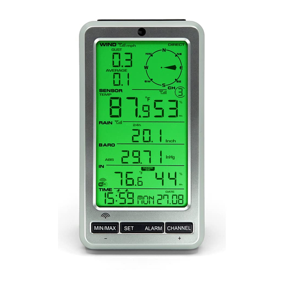
Page 30: Display Features
Figure 44 1. Temperature 8. Low power indicator 2. Temperature units (°F or °C) 9. Humidity Calibrated Icon (when the calibration is 3. Temperature, Rate of Change indicator displayed) 4. Temperature Calibrated Icon (when the 10. Humidity Comfort Colorful Icon calibration is displayed) 11. -
Page 31: Indoor Thermo-Hygrometer Sensor Operation
The comfort icon is based on humidity ranges specified in Figure 45. RH<45% RH 45%~65% RH >65% Comfortable Figure 45 Rate of Change Icon The rate of change icon detects rapid changes in temperature and humidity. If the arrow points upward, the temperature is increasing at a rate of +2°F per 30 minutes (or greater), or humidity is increasing at a rate of +5% per 30 minutes (or greater). -
Page 32: Backlight Operation
Display Maximum. Press the MIN/MAX button once to display the maximum. The MAX icon will be displayed. Clear Maximum. To reset the maximum values to the current values, press and hold the MIN/MAX button for 3 seconds. Display Minimum. Press the MIN/MAX button again to display the minimum. The MIN icon will be displayed. - Page 33 or newspapers. They are in a different location and typically update once per hour. The purpose of your weather station is to measure conditions of your surroundings, which vary significantly from location to location. Humidity Calibration To enter the humidity calibration mode, press and hold the SET and MIN/MAX buttons at the same time for 3 seconds, and the humidity value will begin flashing.
-
Page 34: Indoor Sensor Installation
digital thermometers are not a good source and have their own margin of error. Place the sensor in a shaded, controlled environment next to the fluid thermometer, and allow the sensor to stabilize for 48 hours. Compare this temperature to the fluid thermometer and adjust the console to match the fluid thermometer. -
Page 35: Weather Station Installation Guide And Limitations
Figure 47 Place the console at least three feet away from computers, TVs, and wireless phones. Avoid transmitting through solid metal barriers, as shown in Figure 48. Figure 48 Weather Station Installation Guide and Limitations Version 1.4 ©Copyright 2020, Ambient LLC. All Rights Reserved. Page 35... -
Page 36: Pre-Installation Checkout
Please take this into consideration when choosing console or mounting locations. Make sure your display console is at least five feet away from any electronic device to avoid interference. Visit Ambient Weather Mounting Solutions for assistance and ideas for mounting your weather station: http://www.ambientweather.com/amwemoso.html Best Practices for Wireless Communication Wireless communication is susceptible to interference, distance, walls, and metal barriers. -
Page 37: Display Console Set Up
transmitters or receivers to avoid intermittent communication. 3. Line of Sight Rating. This device is rated at 300feet line of sight (no interference, barriers, or walls) but typically you will get 100feet maximum under most real-world installations, which include passing through barriers or walls. -
Page 38: Display Power Up
Figure 49 1. Outdoor temperature HI/LO alarm icon 15.Indoor humidity display 2.Outdoor temperature display 16.Indoor humidity HI/LO alarm icon 3.Rainfall display (1h, 24h, week, month, 17. 24hour for clear total) 18. Pressure units (Hpa, inHg and mmhg) 4.Rainfall value for 24H 19. - Page 39 Make certain the weather station sensors are at least 10'away from the console and within 100'of the console. If the weather station is too close or too far away, it may not receive a proper signal. If you have more than one thermo-hygrometer transmitter, make sure they are all powered up and transmitting on different channels.
-
Page 40: Sensor Operation Verification
Note: The power adapter is intended to be correctly oriented in a vertical or floor mounted position. The prongs are not designed to hold the plug-in place if it is plugged into a ceiling, under-the-table or cabinet outlet. Figure 51 Note: If the power adapter is plugged in, AC ON will display in the time area for three seconds when powered up. -
Page 41: Console Operation
sensors to stabilize. Console Operation Note: The console has five buttons for easy operation: MIN/MAX /-(WIFI), SET, LIGHT/SNOOZE, ALARM and CHANNEL/+, button. 10.1 Quick Display Mode Command Mode Settings [SET] Time/second, Time/week Press CHANNEL/+ to alternate the display between date/year display. Time/second, Time/week and date/year. -
Page 42: Channel Selection
Command Mode Settings [SET] 12/24 Hour Format (FMT) Press [+] to alternate between 12-hour (am and pm) seconds (default: 12 hour) and 24-hour (military or European) Time. [SET] Change Hour Press [+] or [-] to adjust the hour up or down. [SET] Change Minute Press [+] button or [-] to adjust the minute up or... -
Page 43: Sensor Search Mode
Sensor Search Mode If any of the sensor communication is lost, dashes (--.-) will be displayed on the screen. To reacquire the signal: Press and hold the CHANNEL/+ button for 3 seconds to enter the sensor search mode. Press [+} to alternate between the following sensors: CH1 –... -
Page 44: Restore Factory Default
Restore Factory Default To restore the console to factory default (Wi-Fi network, Weather server and display): Remove the batteries Press and hold the MIN/MAX/- button and put the batteries back in. Wait three seconds after installing the batteries to let go of the MIN/MAX/- button. Snooze Mode When the alarm sounds and alarm icon flashes, tap the SNOOZE/LIGHT button to temporarily silence... -
Page 45: Adjustment Or Calibration
The purpose of your weather station is to measure conditions of your surroundings, which vary significantly from location to location. The WS-50-C supports up to eight remote sensors. Each of the eight sensors can be calibrated. Temperature Calibration In normal mode, press and hold the SET and CHANNEL/+ buttons at the same time for five seconds to enter the temperature calibration mode. -
Page 46: Absolute And Relative Barometer, Wind And Rain Calibration
Press the SET button switch to channel humidity 1through 8. To exit the calibration mode at any time, press the SNOOZE/LIGHT button on the top of the display console. If no operation is performed, the calibration mode will timeout in 30 seconds. Note: Humidity is a difficult parameter to measure accurately and drifts over time. - Page 47 Press the ALARM button to reset current value. Example: The calibrated pressure source measures 28.00 inHg. The display absolute pressure reads 28.83 inHg on the console. Offset = 28.00 – 28.83 = 0.83 inHg. Relative Pressure Calibration Press the SET button and the relative pressure offset will flash. The default is 0.00 inHg Press the [+] or [-] button to increase or decrease the relative pressure offset.
-
Page 48: Clearing Rain Totals
Calibrated Wind Speed = Calibration factor x Measured Wind Speed Press and hold the [+] or [-] button for three seconds to increase or decrease rapidly. Press the ALARM button to reset current value. Note: The wind gust is also affected by the wind speed calibration factor. Discussion: Wind speed and wind gust are adversely affected by installation constraints. -
Page 49: Alarm Mode
0. This will also clear 1h, 24h, week and total rain. Alarm Mode The WS-50-C includes time alarm, temperature alarm and humidity alarm features for indoor and Channel 1, feels like and dew point alarm for Channel 1, wind speed, wind gust, rainfall (1h and 24h) and pressure (ABS and REL) alarm. -
Page 50: Setting The Alarms
Alarm 1 and Alarm 2. Press the ALARM button again to enter the alarm viewing mode to view LOW alarms along with the Alarm 2 Time (AL2). Press (do not hold) the SET button to toggle between Temperature, Dew Point and Feels Like Absolute (ABS) and Relative (REL) Pressure Alarm 1 and Alarm 2. -
Page 51: Alarm And Command Button Beeper On/Off Mode
Rainfall (1h) high alarm Rainfall (24h) high alarm Absolute pressure high alarm Absolute pressure low alarm Relative pressure high alarm Relative pressure low alarm Indoor temperature high alarm Indoor temperature low alarm Indoor humidity high alarm Indoor humidity low alarm Alarm and Command Button Beeper ON/OFF Mode The beeper can be silenced for both alarms and button strokes. -
Page 52: Connect Your Device To The Console's Wifi
The WS-50-C includes a Wi-Fi chip that connects to the 2.4 GHz band on your router and sends data automatically once per minute to our cloud services, AmbientWeather.net. AmbientWeather.net captures, stores, and sends data to other services, such as WeatherUndergroud.com, PWSWeather.com, IFTTT, Amazon Alexa, Google Home and more. - Page 53 Example 2. Connect to the console Wi-Fi server with a Mac. Select the Settings icon Network. Connect to the WeatherHome Wi-Fi network, as shown in Figure 53 (your Wi-Fi network name may be slightly different but will always begin with WeatherHome). Figure 53 Example 3.
-
Page 54: Accessing The Console's Web Interface
Figure 54 Example 4. Connect to the console Wi-Fi server with an Android. From the Apps icon, tap the Settings icon and Wi-Fi. Connect to the WeatherHome Wi-Fi network, as shown in Figure 55 (your Wi-Fi network name may be slightly different but will always begin with WeatherHome). - Page 55 Once connected to the console Wi-Fi, open any web browser, and enter the following IP address into the address bar: http://192.168.5.1 to access the console's web interface. Note: Some browsers will treat 192.168.5.1 as a search, so make sure you include the header http://, http://192.168.5.1 not 192.168.5.1.
- Page 56 If you have a hidden SSID, enter the SSID manually. Time Zone Settings (default: 0h). based on the number of hours from Coordinated Universal Time, or Greenwich Mean Time (GMT). The following table provides times zones throughout the world. Locations in the eastern hemisphere are positive, and locations in the western hemisphere are negative.
-
Page 57: Ambientweather.net
Figure 57 If the connection is successful, the Wi-Fi console's Wi-Fi icon will stop flashing and remain on. When the console successfully connects and uploads to AmbientWeather.net, the data signal icon will appear above the Wi-Fi icon. If the data signal icon is flashing, the console is currently uploading to the server. -
Page 58: Ambient Weather Apps
Register an account on AmbientWeather.net (email address and password). Once registered, select the dashboard to view your data, as shown in Figure 59. Figure 59 Ambient Weather Apps You can view your device online either through a web browser, or apps for Android and iOS devices. AmbientWeather.net is a responsive design and mobile friendly, so there is no need for an app on your desktop, laptop, tablet, or mobile device. -
Page 59: Third Party Public Websites
The Ambient Weather Dashboard app is available on both Android and iOS. Search the Google or Apple Store for Ambient Weather Dashboard. Third Party Public Websites WeatherUnderground.com and PWSWeather.com are third party public websites. You can also report to these websites through the AmbientWeather.net hosting service. To register and send data to the websites, go to the Devices panel on your AmbientWeather.net dashboard:... -
Page 60: Glossary Of Terms
Once connected to the console Wi-Fi, open any web browser, and enter the following IP address into the address bar: http://192.168.5.1/upgrade.html to access the console's upgrade web interface. Tap Select File and browse to the binary (bin) file you downloaded to your PC or Mac. Figure 60 Once complete, you must reset the console to factory default: 1. -
Page 61: Specifications
Term Definition Accuracy Accuracy is defined as the ability of a measurement to match the actual value of the quantity being measured. Hygrometer A hygrometer is a device that measures relative humidity. Relative humidity is a term used to describe the amount or percentage of water vapor that exists in air. -
Page 62: Power Consumption
The following table provides specifications for the measured parameters. The following table provides specifications for the measured parameters. Measurement Range Accuracy Resolution Indoor Temperature 32 to 140 °F ± 1 °F 0.1 °F Outdoor Temperature -40 to 140 °F ± 1 °F 0.1 °F Indoor Humidity 10 to 99 %... -
Page 63: Maintenance
Solar Radiation Shield improves temperature accuracy for hot weather SRS100LX Temperature climates. Install over thermo-hygrometer. and Humidity Solar Radiation Shield Ambient Weather Humidity One step calibration kits for digital hygrometers use salt slurry formula Calibration Kits to accurately calibrate the indoor and outdoor hygrometers. Liability Disclaimer Please help in the preservation of the environment and return used batteries to an authorized depot. -
Page 64: Warranty Information
This product is not a toy. Keep out of the reach of children. No part of this manual may be reproduced without written authorization of the manufacturer. Ambient, LLC WILL NOT ASSUME LIABILITY FOR INCIDENTAL, CONSEQUENTIAL, PUNITIVE, OR OTHER SIMILAR DAMAGES ASSOCIATED WITH THE OPERATION OR MALFUNCTION OF THIS PRODUCT. -
Page 65: California Prop 65
California Prop 65 WARNING: Use of the Ambient Weather Products can expose you to chemicals, including lead and lead compounds, which are known to the State of California to cause cancer and bisphenol A (BPA), and phthalates DINP and/or DEHP, which are known to the State of California to cause birth defects or other reproductive harm. - Page 66 Proposition 65 does not clarify whether exposure is to be measured only in normal operation, or in the event of misuse such as intentionally damaging, incinerating or consuming an Ambient Weather Product or component and Ambient Weather has not attempted to evaluate the level of exposure.
Need help?
Do you have a question about the WS-50-C and is the answer not in the manual?
Questions and answers