
Related Manuals for IAME REEDSTER 125cc


Summary of Contents for IAME REEDSTER 125cc
- Page 1 REEDSTER 125cc F1 - F2 - F3 - F4 Versions ASSEMBLY INSTRUCTIONS & USER MANUAL MAN-051 ING 09/03/07...
-
Page 2: Table Of Contents
I N D E X N° Page Section 1 DESCRIPTION OF THE “Parilla REEDSTER 125cc”ENGINE 1.1. Main features 1.2. Engine characteristics / operation limits 1.3. Contents of the packing 1.4. Accessories 1.5. Motor identification number Section 2 PREPARATION & INSTALLATION OF THE ENGINE ON THE CHASSIS 2.1. -
Page 3: Section 1 Description Of The "Parilla Reedster 125Cc"Engine
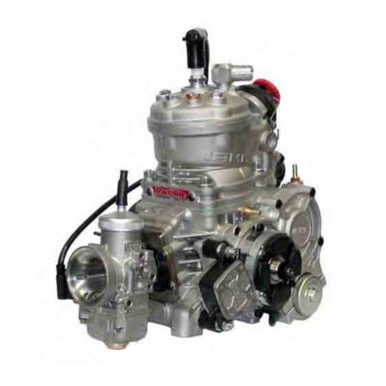
Section 1 - DESCRIPTION OF THE “Parilla REEDSTER 125cc”ENGINE 1.1 MAIN FEATURES The “Parilla Reedster” engine is the result of the decennial racing experience of IAME and it contains many technological and construction innovations which enable the engine to achieve both high performance and guarantee excellent reliability and endurance characteristics. - Page 4 14000rpm (F3 e F4) / 15000rpm (F2) / 16000rpm (F1) • Min. water temperature: 45°C • Max. water temperature: 65°C ATTENTION: Never exceed the above limits; no obligation of IAME exists in case the above limits are exceeded. MAN-051 ING...
-
Page 5: Contents Of The Packing
1.3 CONTENTS OF THE PACKING Each “Parilla Reedster 125cc” engine is supplied with the under shown components and accessories: EXHAUST SYSTEM Quantity • Power valve on the exhaust duct 1 (excepted F3) • Exhaust springs • Exhaust fitting with spacer •... -
Page 6: Accessories
1.4 ACCESSORIES NGK SPARK PLUG EXHAUST SYSTEM BATTERY WITH SUPPORT CLUTCH COVER / H.T. COIL COMPLETE ELECTRIC SYSTEM THERMOSTAT FUEL PUMP CARBURETTOR INLET SILENCER RADIATOR SUPPORT KIT RADIATOR WATER HOSES KIT MAN-051 ING... -
Page 7: Motor Identification Number
NOTE: In case of need for spares and when contacting the IAME Support Centers, please always refer to the Motor Identification Number and to the motor model. MAN-051 ING... -
Page 8: Section 2 Preparation & Installation Of The Engine On The Chassis
Section 2 - PREPARATION AND INSTALLATION OF THE ENGINE ON THE CHASSIS NOTE: In case the engine is supplied already assembled on the chassis, it is at care of the assembler to follow these instructions. The final customer, in this case, can skip this section and can start reading from section 3. - Page 9 2.2 INSTALL THE WATER COOLING SYSTEM (only for F3 - F4) BEFORE INSTALLING THE RADIATOR PREASSEMBLE THE FOLLOWING COMPONENTS INSTALL THE 4 RUBBER DAMPENERS IN THE RADIATOR FIXING HOLES (SEE FIG.1). RUBBER DAMPENERS Fig.1 - PLACE THE RADIATOR SUPPORT BRACKET BETWEEN THE RADIATOR FIXINGS BY TILTING ONE END AND INSERTING IT THROUGH THE RUBBER DAMPENERS (SEE FIG.2)
- Page 10 - COMPLETE INSERTION OF THE Fig.3 RADIATOR SUPPORT BRACKET IN THE RUBBER DAMPENERS (SEE FIG.3 AND Fig.4 Fig.5 FIX THE RADIATOR SUPPORT BRACKET RADIAT. FIXING BRACKET INSERTING ALSO THE RADIATOR FIXING BRACKET (RADIATOR CAP SIDE – N°1 “Z” SHAPE BRACKET SCREW M6x90 AND N°1 SCREW M6x85 WITH NUT).
- Page 11 PLACE THE RADIATOR SO THAT THE HOLE RADIATOR FIXING BRACKET MATCHES WITH ONE OF THE UPPER HOLES ON THE BEARING SUPPORT BOX (SEE FIG.7). ONCE YOU FIND THE CORRECT POSITION, TIGHTEN THE M8x45 SCREW AND M8X65 ON THE LOWER “Z” SHAPE BRACKET THUS FIXING THE RADIATOR .
-
Page 12: Preparation And Installation Of The Motor-Mount
INITIAL PREPARATION OF THE ENGINE 2.3.1 ON THE EXHAUST POWER VALVE THERE IS A WARNING TAG TO REMIND THE USER THAT THE GEAR BOX MUST BE FILLED WITH OIL BEFORE STARTING THE ENGINE (SEE FIG.1). NOTE: ENGINE SUPPLIED WITH EXHAUST FITTING AND SPACER ALREADY PRE-INSTALLED. - Page 13 2.4.2 INSTALL THE MOTOR-MOUNT: MAKE SURE TO USE M8 ALLEN SCREWS WITH A LENGTH SUCH AS TO ENGAGÈ, IN THE CRANKCASE THREADED LENGTH APPROX. 16÷19mm (THE SCREWS MUST PROTRUDE FROM THE PLATE FOR APPROX 16÷19mm - SEE FIG. 3 AND DRAWING PAGE 4 M8 ALLEN SCREWS –...
- Page 14 Fig.6 F4 VERSION (FLOAT CHAMBER CARB) 2.5.3 INSTALLATION OF THE FUEL PUMP (IF NOT ALREADY ASSEMBLED IN ORIGIN) INSTALL THE VIBRATION DAMPENERS ON THE GEAR BOX COVER I (SEE FIG. 6). PLACE THE FUEL PUMP WITH THE OUTLET FITTING TOWARDS THE UPPER SIDE AND TORQUE THE SELF-LOCKING NUTS M6.
- Page 15 REMOVE THE OIL LEVEL PLUG (FRONT PART OF THE ENGINE) (SEE FIG.11). HEXAGONAL WRENCH - 4mm Fig.11 2.6.2 FILL WITH 33cc “IAME EP100”OIL THE GEAR BOX (SEE FIG.12). NOTE: IF THE LEVEL IS CORRECT YOU WILL SEE A LIGHT OUTCOME OF OIL FROM THE OIL LEVEL PLUG.
- Page 16 INSTALLATION OF THE ENGINE ON THE CHASSIS 2.7.1 PLACE THE ENGINE ON THE TWO SIDE RAILS AND SECURE THE MOTOR-MOUNT WITH THE TWO CLAMPS (SEE FIG.13) SUGGESTION: TIGHTEN THOROUGHLY CLAMPS UNTIL CHAIN INSTALLED AND PROPERLY ALIGNED . Fig.13 2.7.2 CHECK THE ALIGNMENT OF THE ENGINE SPROCKET AXLE...
- Page 17 INSTALLATION OF THE CLUTCH COVER WITH H.T. COIL 2.8.1 CONNECT THE H.T. COIL GROUND CABLE TO THE CRANKCASE BY MEANS OF THE M6 SCREW ON THE FRONT FOOT (SEE FIG.17). TORQUE AT 8 ÷ 10 Nm (70 ÷ 90 in. lb) HEXAGONAL WRENCH - 5 mm ATTENTION: MAKE SURE THAT THE COPPER GROUND...
-
Page 18: Electrical Connections
Fig.19 ELECTRICAL CONNECTIONS (refer attached electrical schematic) NOTE : For a correct installation follow the under shown instructions. 2.9.1 INSERT THE BATTERY STRAP IN THE BATTERY SUPPORT BOX (SEE FIG.19). 2.9.2 PLACE THE BATTERY SUPPORT BOX IN THE FRONT OF THE CHASSIS (UNDER THE FRONT PANEL FAIRING) AND FIX IT WITH THE CLAMPS TO THE LOWER STEERING COLUMN SUPPORT TUBES (M6x25 SCREWS - SEE... - Page 19 2.9.5 –CONNECT THE TERMINAL FROM THE IGNITION WITH THE 8 POLES TERMINAL ON THE HARNESS (SEE FIG.23). -CONNECT THE ONE WAY TERMINAL FROM THE ELECTRIC STARTER WITH THE ONE WAY TERMINAL ON THE HARNESS. (SEE FIG.24). ATTENTION: MAKE SURE THAT THE FIXING TONGUES ARE PROPERLY INSERTED TO GUARANTEE THE BEST POSSIBLE CONNECTION OF THE Fig.23...
- Page 20 2.9.8 CONNECT THE H.T COIL CABLE TO THE HARNESS TERMINAL (SEE FIG.27). ATTENTION: FASTEN THE H.T. COIL CABLE WITH A PLASTIC CLAMP TO AVOID THAT EVENTUAL VIBRATIONS MIGHT DISCONNECT TERMINALS (SEE FIG.28). Fig.27 Fig.28 ELECTRONIC BOX. RELAY 2.9.9 CUT THE DUAL-LOCK FIXING STRAP AND ATTACH IT TO THE REAR OF THE ELECTRONIC BOX, THE STARTER FUSE AND THE RELAY (SEE FIG.29).
- Page 21 2.9.11 CONNECT THE STARTER RELAY TO POLES CONNECTOR HARNESS (SEE FIG.31). Fig.31 2.9.12 DRILL A Ø 22mm HOLE IN THE SIDE EDGE FRONT PANEL FAIRING (ENGINE SIDE); AND INSTALL THE STARTER ASSEMBLY (SEE FIG.32). SECURE THE STARTER ASSEMBLY WITH THE THREADED LOCKING NUT.
- Page 22 2.9.15 DRILL THE FAIRING AND FASTEN Fig.35 THE HARNESS WITH PLASTIC CLAMPS (SEE FIG.35). 2.9.16 DRILL THE FAIRING (CLOSE TO THE Fig.36 BATTERY) AND PLACE THE FUSE-HOLDER BY MEANS OF THE 2 HOOKS OF THE JUNCTION BLOCK (SEE FIG.36). 2.9.17 PLACE THE BATTERY TERMINALS OF THE HARNESS UNDER THE STRAP (SEE FIG.
-
Page 23: Install The Intake Silencer
2.9.19 FIX THE CAP TO THE H.T. CABLE WITH Fig.39 A PLASTIC CLAMP (SEE FIG.39). • INSTALL THE SPARK PLUG. TORQUE AT 20 ÷ 26 Nm (175 ÷ 230 in-lb) • INSTALL THE CAP ON THE SPARK PLUG. NOTE: CORRECT DIGITAL IGNITION OPERATION, THE CAP AND / OR THE SPARK... -
Page 24: Section 3 Use Of The Engine
3.1 CHARGING / DISCHARGING THE OIL IN THE GEARBOX ATTENTION: The engine is supplied without oil in the gearbox. Before starting the engine fill the gearbox with “IAME EP100” motor oil. Starting the engine with a dry gearbox will damage the gears beyond repair - charging the gearbox: Put the engine in horizontal position, unscrew the oil plug (n°1 on the picture), and oil level... -
Page 25: Carburettor Adjustment Guide
3.3 CARBURETTOR ADJUSTMENT GUIDE 1 T.O. LEAN RICH ( L ) LOW SPEED FUEL MIXTURE ( I ) IDLE 1 ¼ T.O. ¾ T.O. ( H ) HIGH SPEED FUEL MIXTURE ADJUSTMENT SCREW 1 ½ T.O. T.O. = TURNS OPEN Hereinafter are shown some basic carbs. - Page 26 F4 engine vers: “DELL’ORTO VHSH30 CS” CARBURETTOR The above settings are those prescribed by IAME for the carb. Dell'Orto VHSH 30 CS, installed on the Parilla REEDSTER engine - in the F4 version. The above table shows the reference setting, for the proper engine operation under different temperature, altitude and atmospheric pressure conditions Should you need an optimized carb.
- Page 27 Fig.3 We will get a richer carburetion by lifting the needle, that is, by moving down the retainer clip to a lower notch; and on the contrary, a leaner carburetion is achieved lowering the needle, that is by lifting the retainer clip to a higher notch (see fig.3).
- Page 28 On the contrary, by increasing the altitude it is necessary to reduce the max. jet size by about 2-3 points for every 350m altitude Increase. The above data are only indicative, as many factors influence the carburetion and only a few among them are ponderable.
- Page 29 3.4 STARTING AND STOPPING THE ENGINE Starting is achieved by the starting key. This is a 3 position key: 1- STOP (key can be removed) 2- RUN 3- START STOP START In STOP position, the battery is disconnected and the engine stop signal is sent to the electronic box.
-
Page 30: Engine Break-In
To stop the engine, proceed as follows: A) Turn the key in STOP position, both from RUN position (1 tripping) or from START position (2 trippings). 3.5 ENGINE BREAK-IN The break-in of the engine must be performed following a few fundamental recommendations: 1. -
Page 31: Exhaust System
3.8 EXHAUST SYSTEM Before every test, make sure that the springs are well hooked and properly in place. In case of breakage, replace the broken spring. Never race the kart without the 2 springs in place, as otherwise the exhaust pipe could vibrate beyond control. Every 10 ÷15 hrs, open the pipe end and make sure that the holes on the internal counter cone are not plugged. - Page 32 Ø0.9mm / L=45mm 2 NOTCHES Ø1mm / L=43mm 15 NOTCHES NOTE ON THE PNEUMATIC POWER- VALVE OPERATION The power-valve chokes the exhaust port opening at low RPM, and achieves a more limited port timing diagram and a reduced exhaust port. The power valve function is to optimize the engine performance up to a given RPM.
-
Page 33: Battery
3.10 BATTERY The battery (12 V – 7.2 Ah) is sealed and without maintenance. In order to lengthen the battery life, it is necessary though to follow a few recommendations: When the tension drops below 12.6V it is necessary to recharge the battery Max. -
Page 34: Warnings On The Electrical System
Only use 5A strip fuse. Use of fuses with higher amperage might damage the electronic box whenever the battery polarity is reversed. 12) Only use sealed lead type batteries as specified by IAME. Only use 12V. batteries. 13) Always disconnect the battery from the electrical system when recharging the battery with an external battery charger, otherwise the internal voltage regulator could be damaged. -
Page 35: Spark-Plug And Thermal Degree
3.12 SPARK PLUG AND THERMAL DEGREE The engine is supplied with a standard NGK BR10EG, which represents a good compromise between the needs of a good break-in and the racing needs in normal conditions. Use of different spark plugs is possible and, as a general information, we are attaching a correspondence list among spare plugs of other brands, based on thermal degree which represents the capacity of the spark plug to dissipate the internal heat. -
Page 36: Choice Of The Best Sprocket Ratio
16000 RPM for F1 (the RPM limiter is calibrated at these values). ATTENTION: Never exceed the above limit. No obligation of IAME exists in case the above limit is exceeded. In case the user wishes to optimize, on the track, the sprocket ratio in order to achieve the best possible performance without abusing the engine, follow the under shown recommendations. - Page 37 The following example should clarify the procedure for optimization of sprocket ratio : assume to use an engine, in the F4 version with a Z=12 sprocket, and that during the preliminary track tests a Z=78 teeth axle sprocket has been used. From the table 1 with Z=12 as engine sprocket and Z=78 on the axle sprocket , a ratio of 6,5 is found.
- Page 38 SPROCKET RATIO TO ACHIEVE MAX. 14500 RPM (F2) Sprocket ratio Max. engine RPM during tests SPROCKET RATIO TO ACHIEVE MAX. 15500 RPM (F1) Sprocket ratio Max. engine RPM during tests MAN-051 ING...
-
Page 39: Section 4 Engine Basic Maintenance
Section 4 - ENGINE BASIC MAINTENANCE 4.1 RECOMMENDATIONS ON CENTRIFUGAL CLUTCH The engine has a low maintenance dry centrifugal clutch. The following prescriptions if carefully followed, will allow a long clutch life. When starting the engine, make sure that the brake pedal is fully pressed to avoid sudden accelerations. - Page 40 4.2 INSTRUCTIONS FOR THE DISASSEMBLY/ASSEMBLY OF THE CLUTCH ATTENTION: the following operations can be performed by a skilled mechanic, under the condition to have available the dedicated tools shown on the text; otherwise it is necessary to apply to an Authorized Service Center. Refer to the following drawing during the operations.
-
Page 41: Gear Timing Schematic
Before assembling the clutch, wash with diluent the shaft taper, the connecting hole on the clutch body, the clutch drum and the starter ring. Install clutch 1. Install the starter ring on the clutch body by matching 12 point wrench 10 mm the three holes and the dragging pin (3 screws TE (Torque at 10 Nm) (90 in-lb) (apply “Loctite”... -
Page 42: Scheduled Maintenance
4.4 SCHEDULED MAINTENANCE Following some simple maintenance recommendations will allow the engine to perform more reliably and have a longer life. SCHEDULE COMPONENTS ACTIONS AND COMMENTS Before using Exhaust fitting springs Check status Muffler Check status and fixing Check wear Engine sprocket Check alignment... -
Page 43: Troubleshooting
4.5 TROUBLESHOOTING Below are some common faults, their probable causes and suggested remedy . FAULTS PROBABLE CAUSES REMEDY Starter will not crank when Bad connections on starter cables Check and tighten turning the key to RUN position Bad grounding Check connections and tighten Interruption on fuse Replace (5A) strip fuse, after checking for eventual reversal of... -
Page 44: Engine And Accessories Preservation
4.6 ENGINE AND ACCESSORIES PRESERVATION When engine is to remain out of operation for a long period it must be preserved as follows: Disconnect battery and recharge it periodically (see sect. 3.10) Disconnect carburettor and clean it Seal with tape the engine, inlet and exhaust The external of the engine must be cleaned. - Page 45 MAN-051 ING...
Need help?
Do you have a question about the REEDSTER 125cc and is the answer not in the manual?
Questions and answers