
Related Manuals for IAME X30 125cc RL - TaG


Summary of Contents for IAME X30 125cc RL - TaG
- Page 1 125cc RL - TaG ASSEMBLY INSTRUCTIONS & USER MANUAL - 1 - MAN-043E ENG MAN-043E - ENG...
-
Page 2: Table Of Contents
I N D E X PAGE Section 1 DESCRIPTION OF THE “IAME X30 125cc RL - TaG” ENGINE 1.1. Main features 1.2. Characteristics of the Engine / Operational limits 1.3. Contents of packing 1.4. Accessories 1.5. Motor identification number Section 2 PREPARATION &... -
Page 3: Section 1 Description Of The "Iame X30 125Cc Rl - Tag" Engine
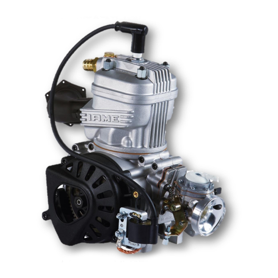
Section 1 - DESCRIPTION OF THE “IAME X30 125cc RL - TaG” ENGINE 1.1 MAIN FEATURES The “IAME X30” has been expressly designed and tuned for powering the karts for hobby racing on closed tracks destined for this specific purpose. -
Page 4: Characteristics Of The Engine / Operational Limits
14.000,15.500 and 16.000 (with rev. limiter) (depending on the versions) Min. water temperature: 45°C Max. water temperature: 65°C WARNING: Never exceed the above limits; no obligation of IAME exists in case the above limits are exceeded. - 2 - MAN-043E ENG... - Page 5 CONTENTS OF THE PACKING Each “IAME X30 125cc RL - TaG” engine is supplied with the accessories under shown: EXHAUST SYSTEM QUANTITY Flexible hose Spring for flexible Exhaust sheath Exhaust manifold Exhaust muffler INDUCTION TRYTON HOBBY 27-C carburettor – Ø26 ...
-
Page 6: Accessories
1.4 ACCESSORIES SPARK PLUG KIT EXHAUST SYSTEM BRUSHES KIT BATTERY SUPPORT KIT THERMOSTAT ELECTRIC PLANT CLUTCH COVER / H.T. COIL CARBURETTOR TRYTON HOBBY RADIATOR SUPPORT KIT WATER PUMP ASSEMBLY INLET SILENCER WATER HOSES KIT RADIATOR - 4 - MAN-043E ENG... -
Page 7: Motor Identification Number
NOTE: In case of need for spares and when contacting the IAME Support Centers, please always refer to the Motor Identification Number and to the motor model. - 5 -... -
Page 8: Section 2 Preparation & Installation Of The Engine On The Chassis
Section 2 - PREPARATION AND INSTALLATION OF THE ENGINE ON THE CHASSIS NOTE: In case the engine is supplied already assembled on the chassis, it is at care of the assembler to follow these instructions. The final customer, in this case, can skip this section and can start reading from section 3. Whenever the engine or a component is disassembled, it is necessary to always follow the under shown Instructions for proper reassembly. -
Page 9: Install The Water-Cooling System
2.2 INSTALL THE WATER COOLING SYSTEM NOTE: to install the water pump belts it is necessary to remove the rear axle. REINSTALL THE REAR AXLE AFTER HAVING Fig.1 INSERTED TWO BELTS. SUGGESTION: INSTALL TWO EXTRA BELTS AS SPARES AND FIX THEM WITH TAPE TO THE AXLE. INSTALL THE WATER PUMP (1 SCREW M8x45 WITH WASHER AND NUT) ON THE PUMP BRACKET ON THE REAR CROSS RAIL... - Page 10 INSTALL THE BELTS AND TENSION (SEE FIG. 4). TIGHTEN THE SCREW M8x45. TORQUE AT 18÷22 Nm (160 ÷190 in-lb) Fig.4 BEFORE INSTALLING THE RADIATOR PREASSEMBLE THE FOLLOWING COMPONENTS INSERT THE 4 RUBBER DAMPENERS INTO THE FIXING HOLES ON THE RADIATOR RUBBER DAMPENER (SEE FIG.
- Page 11 - COMPLETE INSERTION OF THE RADIATOR SUPPORT BRACKET IN THE RUBBER DAMPENERS (SEE FIG. 7 AND 8). Fig.7 Fig.8 RADIATOR SUPPORT BRACKET INSERTING ALSO THE RADIATOR FIXING BRACKET (RADIATOR CAP SIDE – N°1 SCREW RADIATOR FIX. BRACKET. M6x90 AND N°1 SCREW M6x85 WITH NUT). INSTALL THE “L”...
- Page 12 PLACE THE RADIATOR FIXING CLAMP ON THE CHASSIS SIDE RAIL (BRAKE SIDE) (N°2 SCREWS M6x25). TIGHTEN THE BOLTS BY HAND (SEE FIG. 10). PLACE THE RADIATOR SO THAT THE HOLE ON THE RADIATOR BRACKET AND ONE OF THE UPPER HOLES ON THE BEARING SUPPORT BOX MATCH (N°1 SCREW M8) ONCE YOU FIND THE CORRECT POSITION TIGHTENS THE M6x25 SCREWS ON THE...
-
Page 13: Exhaust Header Assembly
Fig.1 EXHAUST HEADER ASSEMBLY NOTE: THE ENGINE IS SUPPLIED WITH THE EXHAUST GASKET AND NUTS ALREADY INSERTED. WHEN THE SHIPMENT IS MADE THE INTERNAL PARTS OF THE ENGINE ARE PROTECTED BY A BLIND GASKET. (SEE FIG. 1). 2.3.1 REMOVE THE NUTS AND THE EXHAUST COVER. - Page 14 6 mm ALLEN WRENCH 2.4.2 INSTALL THE MOTOR-MOUNT, MAKE SURE TO USE THE M8 ALLEN SCREWS, WITH A LENGHT SUCH AS TO ENGAGE, IN THE CRANKCASE, THREADED LENGHT 16÷19mm (THE SCREW MUST PROTRUDE FROM THE PLATE FOR 16÷19mm ). (SEE FIG. 3 AND DRAW. PAG. 11) 4 ALLEN SCREWS M8 TORQUE AT 22÷24 Nm (190 ÷...
- Page 15 2.6 INSTALL ENGINE CHASSIS 2.6.1 POSITION THE ENGINE ON THE TWO OUTSIDE MAIN RAILS AND FIX THE MOTOR- MOUNT WITH TWO CLAMPS. (SEE FIG. 6) SUGGESTION: NEVER TORQUE COMPLETELY THE CLAMPS UNTIL THE CHAIN IS INSTALLED AND PROPERLY ALIGNED. Fig.6 2.6.2 CHECK THE ALIGNMENT OF THE ENGINE SPROCKET AND THE AXLE SPROCKET...
-
Page 16: Install The Clutch Cover With H.t. Coil
2.7 INSTALL THE CLUTCH COVER WITH 5 mm ALLEN H.T. COIL Fig.10 2.7.1 REMOVE THE 3 SCREWS M6x25 ON THE CRANKCASE (SEE FIG.10) AND INSTALL THE CLUTCH COVER WITH H.T. COIL. (SEE FIG.11). TORQUE THE 3 SCREWS AT 8 ÷ 10 Nm (70÷ 90 in-lb). -
Page 17: Mounting Of The Electric Plant And Connectors
MOUNTING OF THE ELECTRIC PLANT AND CONNECTORS (complete scheme in the drawing at the end of the document) NOTE: For a correct installation follow the under shown instructions. MOUNT THE SILENT BLOCKS ON THE UPPER CLAMP (FIG. 13). Fig.13 COMPLETE THE MOUNTING OF THE CLAMPS Fig.14 ON THE BATTERY SUPPORT WITH THE N°4 SCREWS M6x25, N°2 SCREWS FOR EACH... - Page 18 PLACE PLASTIC CLAMPS DEDICATED HOLES AND PUT THE FUSE HOLDER IN POSITION AND THEN TIGHTEN THE PLASTIC CLAMPS TO FIX THE FUSE CASE. CUT OFF EXCEEDING PLASTIC CLAMPS. (Fig.18) Fig.18 MOUNT THE KEY BLOCK IN THE DEDICATED HOUSING. (Fig.19) Fig.19 SLIDE THE BATTERY FIXING STRIPE IN THE DEDICATED SLOTS.
- Page 19 CONNECT THE STATOR PIN WITH THE PIN Fig.23 ON THE CABLES HARNESS. (FIG. 23) CONNECT THE STARTER MOTOR PIN WITH CORRESPONDING CABLES HARNESS. (FIG. 24). WARNING: MAKE SURE THAT THE SECURITY FLAPS SNAP TO GUARANTEE THE CORRECT CONTACT OF THE TWO ENDS AND A SAFE TIGHTENING. Fig.24 VERIFY THE PRESENCE OF THE PLASTIC CLAMP ON THE STARTER MOTOR AND THAT IT FIXES...
- Page 20 ALLEN WRENCH 5 mm FIX THE BUTTONHOLE END OF THE GROUND Fig.27 CABLE THROUGH M6x12 SCREW PRESENT ON THE STARTER ENGINE. (FIG. 27) TORQUE AT 8 ÷ 10 Nm (70÷ 90 in-lb) WARNING: THIS OPERATION IS FUNDAMENTAL AS AN IMPROPER GROUNDING COULD IRREPARABLY DAMAGE THE CELECTRONIC BOX.
- Page 21 CONNECT THE ELECTRONIC BOX TO THE 20 POLES CONNECTOR CABLES HARNESS. ( FIG. 31) CONNECT THE STARTER RELAY TO THE 4 POLES PIN ON THE CABLES HARNESS. (FIG. 32). Fig.31 Fig.32 WARNING: MAKE SURE THAT THE SECURITY FLAPS SNAP TO GUARANTEE THE CORRECT CONTACT OF THE TWO ENDS AND A SAFE TIGHTENING.
-
Page 22: Install The Exhaust
2.10 INSTALL THE EXHAUST NOTE: SEE SECTION 3.8 FOR THE RECOMMENDATIONS ON THE IDEAL EXHAUST LENGHT. 2.10.1 INSTALL THE FLEXIBLE (L= 65mm Fig.37 FLEXIBLE COMPLETELY CLOSED –) AND THE EXHAUST HEADER (SEE FIG. 37) AND FIT THE INSULATING SLEEVE ON THE FLEXIBLE FLEXIBLE (SEE FIG. -
Page 23: Charging Of The Oil In The Gear Box
The engine is suplied without oil in the gear box. Before starting the engine fill the box with SAE 30 oil, for example WLADOIL IAME OIL GEAR. Starting the engine with a dry box will damage the gears beyond repair... -
Page 24: Carburettor Adjustment Guide
3.3 CARBURETTOR ADJUSTMENT GUIDE ( L ) LOW SPEED FUEL MIXTURE ( H ) HIGH SPEED FUEL MIXTURE ( I ) THROTTLE SPEED SCREW 1 T.O. RICH LEAN ¼ ¾ T.O. T.O. ½ T.O. T.O. = TURNS OPEN Normally the correct setting of the mixture screws, after engine run-in, is the following: L (close the screw completely and then open): 1 1/4 T.O. -
Page 25: Starting And Stopping The Engine
3.4 STARTING AND STOPPING THE ENGINE Starting is achieved by the starting key. This is a 3 position key: 1- STOP (key can be removed) 2- KEY 3- RUN In STOP position the battery is disconnected and the engine stop signal is sent to the electronic box. -
Page 26: Engine Running-In
3.5 ENGINE RUNNING-IN The running-in of the engine must be performed following a few fundamental rules: 1. Adjust the carburetion. Start with an adjustment on the rich side. 2. Warm the engine gradually for about 5 minutes at half throttle, making some laps at low speed, gently closing and opening the carb. - Page 27 3.8 EXHAUST SYSTEM Before each test, make sure that the flexible is not damaged. Replace if necessary. WARNING: In case the flexible is damaged, metallic particles could be sucked in the engine and cause a seizure. Always make sure that the springs are well hooked and in place. In case of breakage, replace the broken spring.
- Page 28 3.9 BATTERY The battery (12 V – 9 Ah) is sealed and without maintenance (battery not included in the engine package). In order to lenghten the battery life it is recommended to follow few suggestions: When the tension drops below 12.6V. it is necessary to recharge the battery. ...
-
Page 29: Warnings On The Electrical System
Use of fuses with higher amperage might damage the electronic box whenever the battery polarity is reversed. 12) Only use sealed lead type batteries as specified by IAME. Only use 12V. batteries. 13) Always disconnect the battery from the electrical system when recharging the battery with an external battery charger, otherwise the internal voltage regulator could be damaged. -
Page 30: Spark Plug And Thermal Degree
3.11 SPARK PLUG AND THERMAL DEGREE The engine is supplied with a standard NGK BR10EG spark plug, which represents a good compromise between the needs of a good running-in and the racing needs in normal conditions. Use of different spark plugs is possible and, as a general information, we are attaching a correspondence list among spark plugs of other brands, based on thermal degree which represents the capacity of the spark plug to dissipate the internal heat. - Page 31 According to the different engine versions. WARNING: Never exceed the above limit. No obligation of IAME exists in case the above limit is exceeded. In case the user wishes to optimize on the track the sprocket ratio in order to achieve the best possible performance, without abusing the engine, follow the under shown recommendations.
- Page 32 The following example should clarify the procedure for the optimization of the sprocket ratio. Assume to use the engine with Z=10 teeth engine sprocket and that during the preliminary track tests a Z= 77 teeth axle sprocket has been used. ...
- Page 33 - 31 - MAN-043E ENG...
-
Page 34: Centrifugal Clutch
Section 4 - BASIC MAINTENANCE 4.1 CENTRIFUGAL CLUTCH The engine has a low maintenance dry centrifugal clutch. The following prescriptions, if carefully followed, will allow a clutch longlife. When starting the engine, make sure that the brake pedal is fully pressed to avoid sudden accelerations. - Page 35 4.2 INSTRUCTIONS FOR THE DISASSEMBLY/ASSEMBLY OF THE CLUTCH WARNING: the following operations can be performed by a skilled mechanic, under the conditions to have available the dedicated tools shown in the text, otherwise it is necessary to apply to an Authorized Service Center. Refer to the following drawing during the operations.
-
Page 36: Gear Timing Schematic
Before assembling the clutch, wash with diluent the shaft taper, the connecting hole on the clutch body, the clutch drum and the starter wheel. Install clutch 1. Install the starter wheel on the clutch hub by matching Allen wrench 5mm – T type ... -
Page 37: Replacement Of The Starter Brushes
4.4 REPLACEMENT OF THE STARTER BRUSHES OPERATIONS PICTURES DISASSEMBLE THE STARTER - UNSCREW N°2 SCREWS M6x35 (see Fig.1). (5mm ALLEN WRENCH – T TYPE) Fig.1 Fig.2 - REMOVE STARTER (see Fig.2). Fig.2 NOTE: ON THE ENGINES MANUFACTURED AFTER SEPTEMBER ‘05, THE STARTER CAN BE REMOVED WITHOUT TAKING AWAY THE GEARS COVER BUT SIMPLY BY REMOVING THE... - Page 38 OPENING THE STARTER Fig.3 Fig.1 REMOVE THE PLASTIC CLAMP AND UNSCREW THE SCREW M4 FIXING THE INPUT CABLE TO THE STARTER (see Fig.3) (PHILLIPS SCREWDRIVER) Fig.4 - UNSCREW 3 SCREWS M5 “C” (see Fig.4) (PHILLIPS SCREWDRIVER) - 36 - MAN-043E ENG...
- Page 39 - REMOVE DRUM FROM STARTER Fig.4 KEEPING ROTOR IN ITS SEAT (BE SURE TO HOLD THE ROTOR ON ITS TOOTHED SIDE TO PREVENT BRUSHES FROM FALLING OUT FROM THEIR SEAT) (see Fig.5) Fig.5 Fig.6 - REMOVE ROTOR FROM STARTER HEAD (see Fig.6) ATTENTION: WHEN EXTRACTING ROTOR, THE BRUSHES...
- Page 40 - REMOVE SILICONE FROM BRUSHES WITH A SCREWDRIVER (see Fig.9). - REMOVE SPRINGS Fig.9 - MAKING PRESSURE EXTERNALLY ON THE TIN Fig.9 PLATE TERMINAL, REMOVE BRUSH. (see Fig.10). Fig.10 - INSTALL NEW BRUSH TERMINAL INSIDE (see Fig.11). - PLACE LITTLE RUBBER CAP ON THE TERMINAL Fig.11 - REINSTALL THE PLATE AND FIXE IT WITH THE 2 SCREWS M4...
- Page 41 REPLACEMENT OF THE BRUSH “B” Fig.13 - UNLOOSE THE SCREW M3 “G” (see Fig.13) - EXTRACT THE BRUSH - FIX THE NEW BRUSH WITH SCREW M3 (PHILLIPS SCREWDRIVER) CLOSING THE STARTER - INSERT THE NEW BRUSH SPRING "A" INTO ITS SEAT. - INSTALL THE BRUSH .
- Page 42 - CHECK THAT O-RING "H" IS INSTALLED ON THE STARTER HEAD. - INSERT STARTER DRUM ON THE HEAD BEING CAREFUL TO PREVENT ROTOR FROM ROTATING AND TO PREVENT THE BRUSHES FROM FALLING OUT OF THEIR SEAT (see Fig. 17). Fig.17 - SCREW THE 3 SCREWS M5 (see Fig.18).
- Page 43 4.5 - TROBLESHOOTING Below are some common faults, their probable causes and suggested remedy. FAULTS PROBABLE CAUSES REMEDY Starter will not crank when turning Bad connections on starter cables Check and tighten the key to RUN position. Bad grounding Check connections and tighten Interruption on fuse Replace strip...
- Page 44 4.6 - ENGINE PRESERVATION When engine is to remain unoperative for a long period it must be preserved as follow: Disconnect the battery and charge it periodically; Disconnect carburetor and clean it; Seal with tape the engine inlet and exhaust. The external of the engine must be cleaned.
-
Page 45: Scheduled Maintenance
4.7 SCHEDULED MAINTENANCE The properly and timely execution of inspections and the respect of the program of checks, are the best warranties for safe utilization and durable engine. SCHEDULE COMPONENTS ACTIONS AND COMMENTS Before every using Exhaust flexible Check status Exhaust spring Check status Insulating sleeve... - Page 46 4.8 - WEAR STATUS EVALUATION TABLE - BEARINGS AND HALFCRANKSHAFT NOTE: ALWAYS CHECK DIMENSIONS IN DIFFERENT POINTS ON CIRCUMFERENCE, LOOKING FOR EVENTUAL OVALIZATIONS. On the following Table are shown the ovalization limits above which replacement is required. MEASURED PART LIMITS (MEASURING INSTRUMENT) CRANKSHAFT –...
- Page 47 4.9 – MAIN PRESCRIPTIONS CRANKSHAFT MATCHING THE PISTON Diametro sede cuscinetto su un motore nuovo Refer to the attached table to determine wear status of the crankshaft halves. ATTENTION Play between piston and the liner must be Replace the part when the flow rate of the bearing 0.11÷0.12mm.
- Page 48 5.0 - MATCHING PLAYS – CONROD LOWER AND UPPER END - 46 - MAN-043E ENG...
-
Page 49: Torque Value
5.1 - TORQUE VALUES VALUES VALUES NOMINAL SIZE Q.TY FASTENER NAME WRENCH (Nm) (in*lb) M14x1,25 Spark plug Hex.20,8 20 ÷ 26 175 ÷ 230 M8x1,25 Head and cylinder nut Hex.13 18 ÷ 22 160 ÷ 190 M8x1,25 Exhaust Header nut Hex.13 18 ÷... -
Page 50: Cross Pattern Locking Order On Crankcase
5.2 - CROSS PATTERN LOCKING ORDER ON CRANKCASE - 48 - MAN-043E ENG... -
Page 51: Overhaul Tool List
5.3 - OVERHAUL TOOL LIST SPECIFIC TOOLS AVAILABLE AT IAME DESCRIPTION P.N. 10271 PISTON FITTING 10270 CLUTCH LOCKING WRENCH 10272-C CLUTCH DISASSEMBLY TOOL 10200 PISTON PIN FITTING 10120 PISTON CIRCLIP ASSEMBLY TOOL 10110B-C CRANKSHAFT ASSEMBLY KIT... - Page 52 5.4 – FIXING TOOL ON VICE BENCH - 50 - MAN-043E ENG...
- Page 53 5.5 –BEARING/OIL SEAL ASSEMBLY TOOL - DISEGNO S725/1 - 51 - MAN-043E ENG...
-
Page 54: Wiring Diagram
5.6 – WIRING DIAGRAM ELECTRONIC BOX RELAY STARTER KEY FUSE HOLDER BATTERY IGNITION STARTER MOTOR H.T. COIL MAN-043E ENG...
Need help?
Do you have a question about the X30 125cc RL - TaG and is the answer not in the manual?
Questions and answers