
Related Manuals for IAME Parilla LEOPARD


Summary of Contents for IAME Parilla LEOPARD
- Page 1 All manuals and user guides at all-guides.com LEOPARD 125cc RL TaG K engine ISTRUZIONI DI MONTAGGIO ASSEMBLY INSTRUCTIONS & & DI UTILIZZO USER MANUAL MAN048 ING ...
- Page 2 All manuals and user guides at all-guides.com INDEX Page GENERAL DESCRIPTION OF THE ENGINE 1 CHARACTERISTICS OF THE "LEOPARD" ENGINE – OPERATIONAL LIMITS 2 1 Contents of the packing 2 2 Motor identification Number 4 3 Preparation and installation of the engine on the chassis 5 3.1 Installation sketch of the engine on the chassis 5 3.2 Install the water cooling system 6 3.3 Exhaust header assembly 10 3.4 Preparation and installation of the motormount 10 3.5 Install the carburetor 11 3.6 Install the engine on the chassis 13 3.7 Install the clutch cover with H.T. coil 14 3.8 Electrical connections 15 ...
-
Page 3: General Description Of The Engine
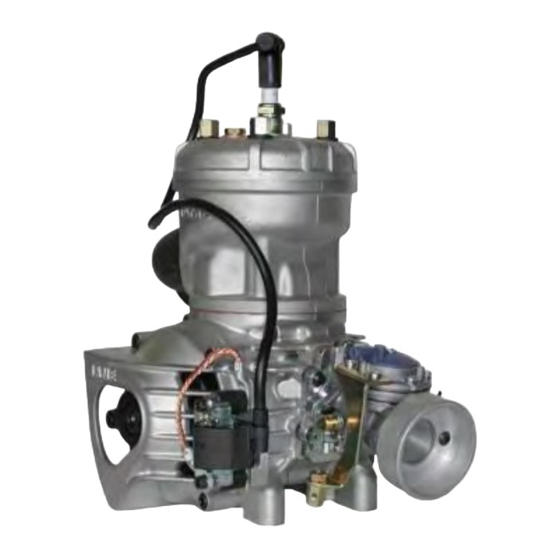
All manuals and user guides at all-guides.com GENERAL DESCRIPTION OF THE ENGINE This engine of the "TaG" series (Touch and Go) has been expressly designed and developed for the powering of karts for hobby racing on closed tracks, destined for this specific purpose. When designing this new line of engines, the technical solutions already adopted for the high performance engines were used, in order to guarantee the highest reliability of components, when the operating limitations are respected. ... -
Page 4: Contents Of The Packing
· Electric start: 12V/0.30 Kw · Clutch: Automatic, dry, centrifugal Operational limits: · Max. RPM : 17000 RPM (with rev. limiter) · Min. water Temperature: 45°c · Max. water Temperature: 65°c ATTENTION: Never exceed the above limits, no obligation of IAME exists in case the above limits are exceeded. 1 CONTENTS OF THE PACKING Each Leopard engine is supplied with the accessories under shown: EXHAUST SYSTEM QuantitY · Flexible · Spring for flexible ·... - Page 5 All manuals and user guides at all-guides.com ACCESSORIES EXHAUST SYSTEM NGK SPARK PLUG BATTERY WITH SUPPORT CLUTCH COVER / H.T. COIL COMPLETE ELECTRIC ASSEMBLY ADDITIONAL ENGINE PLATE STARTER BRUSHES KIT INTAKE SILENCER TILLOTSON CARBURETOR RADIATOR SUPPORT KIT COMPLETE PUMP GROUP WATER HOSE KIT RADIATOR 3 MAN048 ING ...
-
Page 6: Motor Identification Number
4 digits (there can be exceptions in some special cases). Other numbers stamped on the crankcase or other surfaces of the motor refer to various manufacturing processes and do not identify the motor. NOTE: In case of need for spares and when contacting the IAME Support Centers, please always refer to the Motor Identification Number and to the motor model. 4 MAN048 ING ... -
Page 7: Preparation And Installation Of The Engine On The Chassis
All manuals and user guides at all-guides.com 3 PREPARATION AND INSTALLATION OF THE ENGINE ON THE CHASSIS NOTE: In case the engine is supplied already assembled on the chassis, it is at care of the assembler to follow these instructions. The final customer, in this case, can skip this section and can start reading from section 4. Whenever the engine or a component is disassembled, it is necessary to always follow the under shown instructions for proper reassembly. 3.1 INSTALLATION SKETCH OF THE ENGINE ON THE CHASSIS 5 MAN048 ING ... -
Page 8: Install The Water Cooling System
All manuals and user guides at all-guides.com 3.2 INSTALL THE WATER COOLING SYSTEM NOTE: To install the water pump belts it is necessary to remove the rear axle. 1 REINSTALL THE REAR AXLE AFTER Fig.1 HAVING INSERTED TWO BELTS SUGGESTION: INSTALL OTHER TWO BELTS AS SPARES AND FIX THEM WITH TAPE TO THE AXLE. 2 INSTALL THE WATER PUMP (1 SCREW M8x45 WITH WASHER AND NUT) ON THE PUMP BRACKET ON THE REAR CROSS RAIL (SEE FIG. 1). TORQUE AT 18÷22 Nm (160÷190 inlb) IN CASE THERE IS NO BRACKET FOR THIS PURPOSE IT IS NECESSARY TO INSTALL THE PUMP ON REMOVABLE CLAMPS AVAILABLE IN DIFFERENT DIAMETERS (Æ28/30/32mm). ASSEMBLE THE PUMP FIXING BRACKET ON THE CLAMP (N°2 SCREWS M6x12) AND PLACE THE CLAMPS ON THE REAR CROSS RAIL (N°2 SCREWS M6x25). INSTALL THE PUMP ON THE BRACKET (N°1 SCREW M8x45 WITH WASHER AND NUT – SEE FIG. 2). TIGHTEN BY HAND THE SCREW ON THE PUMP LETTING IT FREE TO ROTATE FOR PUMP FIX. BRACKET THE ALIGNMENT AND TENSIONING OF THE BELTS. ... - Page 9 All manuals and user guides at all-guides.com 4 INSTALL THE BELTS AND TENSION (SEE FIG. 4). TIGHTEN THE SCREW M8x45 TORQUE AT 18÷22 Nm (160÷190 inlb) Fig.4 BEFORE INSTALLING THE RADIATOR PREASSEMBLE THE FOLLOWING COMPONENTS 5 INSERT THE 4 RUBBER DAMPENERS INTO THE FIXING HOLES ON THE RADIATOR (SEE FIG. 5). RUBBER DAMPENER Fig.5 6 PLACE THE RADIATOR SUPPORT BRACKET BETWEEN THE RADIATOR FIXINGS BY TILTING ONE END AND INSERTING IT THROUGH THE RUBBER DAMPENERS (SEE FIG. 6) NOTE: OIL THE BRACKET ENDS AND THE DAMPENERS HOLES . RADIATOR SUPPORT BRACKET Fig.6 7 MAN048 ING ...
- Page 10 All manuals and user guides at all-guides.com COMPLETE INSERTION OF THE RADIATOR SUPPORT BRACKET IN THE RUBBER DAMPENERS (SEE FIG. 7 AND 8). Fig.7 Fig.8 7 FIX THE RADIATOR SUPPORT BRACKET INSERTING ALSO THE RADIATOR FIXING BRACKET (RADIATOR CAP SIDE – N°1 SCREW M6x90 AND N°1 SCREW M6x85 RADIATOR FIXING BRACKET WITH NUT). SCREW M6X90 INSTALL THE “L” SHAPE BRACKET ON THE LOWER ...
- Page 11 All manuals and user guides at all-guides.com 8 PLACE THE RADIATOR FIXING CLAMP ON THE CHASSIS SIDE RAIL (BRAKE SIDE) (N°2 SCREWS M6x25). TIGHTEN THE BOLTS BY HAND (SEE FIG. 10). Fig.10 9 PLACE THE RADIATOR SO THAT THE HOLE ON THE RADIATOR BRACKET AND ONE OF THE UPPER HOLES ON THE BEARING SUPPORT BOX, MATCH. (N°1 SCREW M8) – (SEE FIG. 11). ONCE YOU FIND THE CORRECT POSITION TIGHTEN, THE M6x25 SCREWS ON THE CLAMP. TIGHTEN AT 8÷10 Nm (70÷90 inlb) ...
-
Page 12: Exhaust Header Assembly
All manuals and user guides at all-guides.com 3.3 EXHAUST HEADER ASSEMBLY NOTE: THE ENGINE IS SUPPLIED WITH THE EXHAUST GASKET AND NUTS ALREADY INSERTED. WHEN THE SHIPMENT IS MADE AN EXHAUST COVER GASKET IS PROVIDED TO PROTECT THE INTERNAL PARTS. 3.3.1 REMOVE THE NUTS AND THE EXHAUST COVER. Fig.1 3.3.2 MAKE SURE THE EXHAUST GASKET IS IN ... -
Page 13: Install The Carburetor
All manuals and user guides at all-guides.com 3.4.2 BEFORE INSTALLING THE MOTOR MOUNT, POSITION THE ADDITIONAL MOUNT Fig.2 PLATE ON THE CRANKCASE (SEE FIG. 2). 3.4.3 INSTALL THE MOTOR MOUNT. MAKE 6 mm. ALLEN WRENCH SURE TO USE M8 ALLEN SCREWS WITH A LENGHT SUCH AS TO ENGAGE, IN THE Fig.3 ... - Page 14 All manuals and user guides at all-guides.com SCREWDRIVER 4.8 mm. 3.5.2 REMOVE 2 SCREWS 3.5mm ON THE Fig.5 CARB. PUMP (IN CORRESPONDENCE OF THE THROTTLE LEVER) (SEE FIG. 5). Fig.6 3.5.3 INSERT THE GAS BRACKET AND THE TWO SCREWS (SEE FIG. 6). ALLEN WRENCH 3 mm 3.5.4 INSTALL THE INTAKE SUPPORT – 2 Fig.7 SCREWS M5 X10 (SEE FIG. 7) 10 mm OPEN WRENCH 3.5.5 INSTALL THE CARBURETOR (SEE FIG. 8 / 9). § REMOVE THE TWO M6 NUTS FROM THE INLET MANIFOLD. § REMOVE THE PLASTIC PLUG FROM THE INLET MANIFOLD. ...
-
Page 15: Install The Engine On The Chassis
All manuals and user guides at all-guides.com Fig.9 ATTENTION: WHEN REPLACING THE CARB. GASKET ALWAYS MAKE SURE THAT THE GASKET IS INSTALLED SO THAT THE HOLE IN THE GASKET MATCHES WITH THE TWO PRESSURE HOLES IN THE CARB. AND IN THE ... -
Page 16: Install The Clutch Cover With H.t. Coil
All manuals and user guides at all-guides.com 3.6.4 MOVE THE ENGINE ON THE RAILS AND OPTIMIZE THE CHAIN TENSION . ATTENTION: THE PLAY OF THE CHAIN MUST BE APPR. 15mm (½÷¾ inch) MEASURED IN THE SHOWN POINT (SEE FIG. 13) 15mm Fig.13 3.6.5 TORQUE THE CLAMP SCREWS 3.7 INSTALL THE CLUTCH COVER 5 mm ALLEN WITH H.T. COIL REMOVE THE 3 SCREWS M6 X 30 ON THE CRANKCASE (SEE FIG. 14) AND INSTALL THE ... -
Page 17: Electrical Connections
All manuals and user guides at all-guides.com 3.8 Fig.16 ELECTRICAL CONNECTIONS (Refer to the attached electrical schematic). NOTE: For a correct installation follow the under shown instructions. 3.8.1 INSERT THE BATTERY STRAP IN THE BATTERY SUPPORT (SEE FIG. 16). 10mm BOX WRENCH 3.8.2 PLACE THE BATTERY SUPPORT BOX Fig.17 ... - Page 18 All manuals and user guides at all-guides.com 3.8.5 –CONNECT THE TERMINAL FROM THE Fig.20 IGNITION WITH THE 8 POLE TERMINAL ON THE HARNESS SEE FIG. 20). CONNECT THE ONE WAY TERMINAL FROM THE ELECTRIC STARTER WITH THE ONE WAY TERMINAL ON THE HARNESS (SEE FIG. 21). ATTENTION: MAKE SURE THAT THE FIXING TONGUES ARE PROPERLY INSERTED ...
- Page 19 All manuals and user guides at all-guides.com 5 mm ALLEN 3.8.7 FIX THE HARNESS GROUND CABLE Fig.24 WITH THE EYELET TERMINAL (Ø 6.5mm), ON THE ENGINE CRANKCASE, BY MEANS OF THE PROPER THREADED HOLE (SEE FIG. 24). M6x12 SCREW TORQUE AT 8 ÷ 10 Nm (70 ÷90 inlb) ATTENTION: THIS OPERATION IS EXTREMELY ...
- Page 20 All manuals and user guides at all-guides.com 3.8.10 CUT THE DUALLOCK FIXING STRAP AND ATTACH IT TO THE ELECTRONIC BOX, THE STARTER FUSE, AND THE FUSE HOLDER (SEE FIG.28). RELAY FUSE HOLDER Fig.28 ELECTRONIC BOX. 3.8.11 –CONNECT THE ELECTRONIC BOX TO THE 20 POLE TERMINAL IN THE WIRING HARNESS (SEE FIG. 29). CONNECT THE STARTER RELAY TO THE 4 POLE TERMINAL IN THE WIRING HARNESS (SEE FIG. 30). ATTENTION: MAKE SURE THAT THE FIXING TONGUES ARE ...
- Page 21 All manuals and user guides at all-guides.com Fig.32 3.8.13 CONNECT THE CABLE FROM THE STARTING ASSEMBLY WITH THE 8 POLE TERMINAL IN THE WIRING HARNESS (SEE FIG. 32). ATTENTION: MAKE SURE THAT THE FIXING TONGUES ARE PROPERLY INSERTED TO GUARANTEE THE BEST ...
-
Page 22: Install The Intake Silencer
All manuals and user guides at all-guides.com 3.8.17 PLACE THE WIRING HARNESS BATTERY TERMINALS UNDER THE BATTERY STRAP (SEE FIG. 36). SUGGESTION: NEVER CONNECT THE BATTERY UNTIL YOU ARE READY TO START THE ENGINE. SEAL THE BATTERY TERMINALS WITH PLASTIC TAPE TO AVOID THAT EVENTUAL VIBRATIONS MIGHT DISCONNECT THE TERMINALS. ... -
Page 23: Install The Exhaust
All manuals and user guides at all-guides.com 3.10 INSTALL THE EXHAUST NOTE: SEE SECTION 10 FOR THE RECOMMENDATIONS ON THE IDEAL EXHAUST LENGHT. 3.10.1 INSTALL THE FLEXIBLE (L= 65mm Fig.40 FLEXIBLE COMPLETELY CLOSED) AND THE EXHAUST HEADER (SEE FIG. 40) AND FIT THE INSULATING SLEEVE ON THE FLEXIBLE (SEE FIG. 41). FLEXIBLE Fig.41 INSULATING SLEEVE 3.10.2 INSERT THE FLEXIBLE ON THE EXHAUST HEADER AND FIX WITH THE 3 SPRINGS (SEE FIG. 42). ... -
Page 24: Gasoline And Oil
All manuals and user guides at all-guides.com 4 GASOLINE and OIL Use leaded or unleaded Premium Gasoline (92 RON+MON) mixed with oil at 6% (16:1). Use oils containing Castor Oil which guarantees an optimized lubrication at high temperatures. As on the other hand, use of Castor Oils creates gummy residues which give origin to carbon deposits, it is necessary to check and clean, at least every 5 ÷ 10 hours, the piston and the head. ... -
Page 25: Carburetor Adjustment Guide
All manuals and user guides at all-guides.com 5 CARBURETOR ADJUSTMENT GUIDE ( I ) THROTTLE ( H ) HIGH SPEED FUEL MIXTURE SPEED SCREW ( L ) LOW SPEED FUEL MIXTURE * 1 T.O. RICH LEAN ¼ ¾ T.O. T.O. ½ T.O. * T.O. = TURNS OPEN Normally the correct setting of the mixture screws is the following: § L (close the screw completely and then open): 1 ¼ ÷ 1 ½ T.O. § H (close the screw completely and then open): 1 ÷ 1 ¼ T.O. Based on various factors as altitude, ambient temperature etc. it might be necessary to reset the carburetor to optimize the performance of the engine. ATTENTION: Never lean too much as lean mixture will overheat engine and cause seizure Do not force H or L closed. It may damage the precision machined orifice and render the carb unserviceable. The adjustment of screw must be performed with warm engine. ... -
Page 26: Starting And Stopping The Engine
All manuals and user guides at all-guides.com 6 STARTING AND STOPPING THE ENGINE Starting is achieved by the starting key. This is a 3 position key: 1 STOP (key can be removed) 2 KEY 3 RUN In STOP position the battery is disconnected and the engine stop signal is sent to the electronic box. In KEY position the battery is connected to the system and the stop signal is removed. In RUN position the battery is always connected and the electric starter, operation signal is sent to the electronic box. ATTENTION: The starting key assembly is supplied with two original keys. We recommend to separate the keys and to keep one in a protected place. In case of loss of both keys, it is necessary to replace the complete assembly. ... -
Page 27: Engine Break-In
All manuals and user guides at all-guides.com 7 ENGINE BREAKIN The breakin of the engine must be performed following a few fundamental rules: 1. Adjust the carburetion. Start with an adjustment on the rich side. 2. Warm the engine gradually for about 5 minutes at half throttle,making some laps at low speed, gently closing and opening the carb. throttle (if a tachometer is installed never exceed 11.000 ÷ 12.000 RPM). Never keep the same RPM for a long time. 3. Progressively increase the speed of the kart for 5 minutes at ¾ throttle opening. Never keep the same RPM for a long time. 4. Increase the speed for 5 minutes, at max. speed on the twisty parts of the circuit and making the engine rich at half straight (cover with the hand for an instant the holes on the air filter, keeping the throttle wide open). ATTENTION: Once the breakin is over and the engine is cold, check the torque of the exhaust header nuts as, during the breakin, the nuts tend to become loose (refer to the attached table). 8 RPM LIMITATION The electronic box incorporates an RPM limiter which prevents the engine from exceeding 17000 RPM. This limit cannot be exceeded otherwise the engine could be damaged by the extremely high RPM. ... -
Page 28: Exhaust System
All manuals and user guides at all-guides.com 10 EXHAUST SYSTEM Before every test, make sure that the flexible is not damaged. Replace if necessary. ATTENTION: In case the flexible is damaged, metallic particles could be sucked in the engine and cause a seizure. Always make sure that the springs are well hooked and in place. In case of breakage, replace the broken spring. Never race the kart without the 3 springs in place, as otherwise the exhaust pipe could vibrate beyond control. ... - Page 29 All manuals and user guides at all-guides.com ATTENTION: Once the engine is started, avoid useless accelerations which can overheat and deteriorate the clutch. Oil the chain before each tests, immediately after each race or test, check the engine sprocket. Replace if necessary. A bad alignment of the engine sprocket with the axle sprocket or the lack of oil will damage the chain and sprocket. Check the clutch: § Every 5 hours of use. § When metallic noises are heard inside the clutch. § If the kart dragging speed exceeds 6000 RPM. § Every time the clutch has overheated (presence of smoke or smell of burning). To check the clutch, you must remove the clutch cover and the clutch drum. Replace the clutch: § whenever the thickness of the friction material (see drawing) is lower than 1.5mm on point A of the clutch or if the body diameter is lower than 82.5mm. ...
- Page 30 All manuals and user guides at all-guides.com 12 INSTRUCTIONS FOR THE DISASSEMBLY / ASSEMBLY OF THE CLUTCH ATTENTION: The following operations can be performed by a skilled mechanic under the conditions to have available the dedicated tools shown on the text, otherwise it is necessary to apply to an Authorized Service Center. Refer to the following drawing during the operations. 11 6 A 10 5 9 7 8 1 2 3 A A 4 1 Drum nut 5 Sprocket 9 Cone safety washer 2 External washer 6 Clutch drum 10 Clutch body ...
- Page 31 All manuals and user guides at all-guides.com Before assemblying the clutch, wash with diluent the shaft taper, the connecting hole on the clutch body, the clutch drum and the starter ring. Install clutch § 12 point wrench 10 mm 1. Install the starter ring on the clutch body by matching the 3 holes and the dragging pin. (3 screws M6) (Torque at 10 Nm) (90 inlb) (Apply Loctite on the threads) ATTENTION: make sure to always install the Ø 7 mm dragging pin as, otherwise, the eventual kick backs could break the screws. 2. Insert key on shaft 3. Install clutch body and the cone safety washer. 4. Install the 16 x 1 nut using the clutch wrench. § Clutch wrench P.N. 10270 § 24 mm. socket ATTENTION: turn counterclockwise as nut has (Torque at 40 ÷ 50 Nm) (350 ÷ 440 inlb) left thread. 5. Install the internal washer. ATTENTION: install washer with bevel towards ...
-
Page 32: Warnings On The Electrical System
When the battery comes to an end never throw it in the garbage but deliver it to an § authorized disposer. 14 WARNINGS ON THE ELECTRICAL SYSTEM We are here listing the main warnings on the electrical system. Please keep this in mind during the whole life of the engine. ATTENTION: If these prescriptions are not followed the electrical system and the engine could be damaged beyond repair. No obligation of IAME exists in this case. 1) Please turn the key to STOP position every time the engine is stopped. If the key is left in KEY position, for a long time, even if the engine is stopped, the battery would be discharged completely. 2) Never disconnect the ground cables with eyelets when the engine is in operation. 3) Disconnecting the battery when the engine is in operation DOES NOT increase the engine performance. Vice versa, the ignition advance could become very irregular at low RPM thus reducing the performance. ... -
Page 33: Spark Plug And Thermal Degree
11) Replace the fuse after having disconnected both terminals on the battery. Only use 5A strip fuse. Use of fuses with higher amperage might damage the electronic box whenever the battery polarity is reversed. 12) Only use sealed lead type batteries as specified by IAME. Only use 12V. batteries. 13) Always disconnect the battery from the electrical system when recharging the battery with an external battery charger, otherwise the internal voltage regulator could be damaged. 14) DO NOT connect batteries in parallel; this might cause explosions and damages to ... -
Page 34: Choice Of The Best Sprocket Ratio
The operating limit for the Leopard engine is 17000 RPM and the RPM limiter is calibrated at this value. ATTENTION: Never exceed the above limit. No obligation of IAME exists in case the above limit is exceed. In case the user wishes to optimize on the track the sprocket ratio in order to achieve the best possible performance, without abusing the engine, follow the under shown ... - Page 35 All manuals and user guides at all-guides.com Tab.1 Sprocket Sprocket Teeth n° Engine sprocket Teeht n° Engine sprocket ratio ratio Teeth n° 10 11 Teeth n° 10 11 axle sprocket axle sprocket 72 7,20 6,55 83 8,30 7,55 73 7,30 6,64 84 8,40 7,64 74 7,40 6,73 85 8,50 7,73 75 ...
- Page 36 All manuals and user guides at all-guides.com SPROCKET RATIO TO ACHIEVE MAX. 16500 RPM Engine Max Sprocket ratio RPM. during tests 34 MAN048 ING ...
-
Page 37: Replacement Of The Starter Brushes
All manuals and user guides at all-guides.com 17 REPLACEMENT OF THE STARTER BRUSHES OPERATIONS PICTURES Fig.1 1. DISASSEMBLE THE STARTER UNLOOSE THE SCREW M6X30 ON THE STARTER SUPPORT (see Fig.1). (5mm ALLEN WRENCH – T TYPE) REMOVE THE STARTER SUPPORT Fig.2 3 SCREWS M6X25 (see Fig.2). (5mm ALLEN WRENCH – T TYPE) Fig.3 UNSCREW N°3 SCREWS M6x35 (see Fig.3). (5mm ALLEN WRENCH – T TYPE) REMOVE STARTER Fig.4 (see Fig.4). 35 MAN048 ING ... - Page 38 All manuals and user guides at all-guides.com 2. OPENING THE STARTER Fig.5 Fig.1 REMOVE THE PLASTIC CLAMP AND UNSCREW THE SCREW M4 FIXING THE INPUT CABLE TO THE STARTER (see Fig.5) (SCREWDRIVER) Fig.6 UNSCREW 3 SCREWS M5 “C” (see Fig.6) (SCREWDRIVER) 36 MAN048 ING ...
- Page 39 All manuals and user guides at all-guides.com REMOVE DRUM FROM STARTER Fig.4 KEEPING ROTOR IN ITS SEAT (BE SURE TO HOLD THE ROTOR ON ITS TOOTHED SIDE TO PREVENT BRUSHES FROM FALLING OUT FROM THEIR SEAT) (see Fig.7) Fig.7 Fig.8 REMOVE ROTOR FROM STARTER HEAD (see Fig.8) ATTENTION: WHEN EXTRACTING ROTOR, THE BRUSHES MAY SPRING OUT FROM THEIR SEATS. Fig.9 3. REPLACING THE BRUSH “A” UNSCREW THE 2 SCREWS M4 “D” RETAINING THE PLATE “E” (see Fig.9). (SCREWDRIVER) Fig.10 REMOVE THE LITTLE RUBBER CAP “F” (see Fig.10). (PLIERS) OUR SUGGESTION: SLIGHTLY OIL THE TIN PLATE TERMINAL END, TO MAKE EASIER THE EXTRACTION OF THE LITTLE RUBBER CAP. 37 MAN048 ING ...
- Page 40 All manuals and user guides at all-guides.com REMOVE SILICONE FROM BRUSHES WITH A SCREWDRIVER (see Fig.11). REMOVE SPRINGS Fig.11 Fig.9 MAKING PRESSURE EXTERNALLY ON THE TIN PLATE TERMINAL, REMOVE BRUSH. (see Fig.12). Fig.12 INSTALL NEW BRUSH TERMINAL INSIDE (see Fig.13). PLACE LITTLE RUBBER CAP ON THE TERMINAL Fig.13 REINSTALL THE PLATE AND FIXE IT WITH THE 2 SCREWS M4 (see Fig.14). (SCREWDRIVER) Fig.14 38 MAN048 ING ...
- Page 41 All manuals and user guides at all-guides.com Fig.15 4. REPLACEMENT OF THE BRUSH “B” UNLOOSE THE SCREW M3 “G” (see Fig.15) EXTRACT THE BRUSH FIX THE NEW BRUSH WITH SCREW M3 (SCREWDRIVER) 5. CLOSING THE STARTER INSERT THE NEW BRUSH SPRING "A" INTO ITS SEAT. INSTALL THE BRUSH . KEEP THE BRUSH IN PLACE BY PRESSING TOWARDS THE OUTER AND CLAMP IT WITH AN IRON WIRE BENT AS A HOOK. REPEAT THE SAME PROCEDURE TO INSTALL THE BRUSH “B” (see Fig.16). Fig.16 INSTALL THE STARTER ROTOR BETWEEN THE BRUSHES AND CHECK, THAT THEY ARE ALWAYS IN CONTACT WITH THE CYLINDRIC COPPER PART OF THE ROTOR, EVEN WHEN THEY ARE RELEASED (see Fig.17). ...
- Page 42 All manuals and user guides at all-guides.com CHECK THAT ORING "H" IS INSTALLED ON THE STARTER HEAD. INSERT STARTER DRUM ON THE HEAD BEING CAREFUL TO PREVENT ROTOR FROM ROTATING AND TO PREVENT THE BRUSHES FROM FALLING OUT OF THEIR SEAT (see Fig. 19). Fig.19 SCREW THE 3 SCREWS M5 (see Fig.20). (SCREWDRIVER) CHECK THAT THE STARTER ROTOR ROTATES FREELY. Fig.20 CONNECT THE INPUT WIRING Fig.21 TO THE STARTER WITH THE SCREW M4 (see Fig.21). (SCREWDRIVER) 6. ASSEMBLING THE STARTER PLACE THE STARTER IN SEAT (see Fig.22). OIL ORING TO MAKE EASIER INSTALLATION. N°3 SCREWS TCH M6x35 TIGHTEN AT A 8÷10 Nm ( 70÷90 inlb ) (5mm WRENCH – T TYPE) ...
-
Page 43: Scheduled Maintenance
All manuals and user guides at all-guides.com 18 SCHEDULED MAINTENANCE Following some simple maintenance standards will allow the engine to perform more reliably and have a longer life. SCHEDULE COMPONENTS ACTIONS AND COMMENTS Before using Exhaust flexible Check status Exhaust spring Check status Exhaust strap Check status Silencer Check status and fixing Engine sprocket Check wear Check alignment with axle sprocket Engine chain ... -
Page 44: Troubleshooting
All manuals and user guides at all-guides.com 19 TROUBLESHOOTING Below are some common faults, their probable causes and suggested remedy: FAULTS PROBABLE CAUSES REMEDY Starter will not crank when Bad connections on starter cables. Check and tighten turning the key to RUN position Bad grounding Check connections and tighten. Interruption on fuse Replace 5A strip fuse, after checking for eventual reversal of battery polarity. Damaged cables Replace Battery connections loose Check and tighten Battery discharged Recharge battery ... -
Page 45: Engine Preservation
All manuals and user guides at all-guides.com 20 ENGINE PRESERVATION When engine is to remain unoperative for a long period it must be preserved as follows: § Disconnect the battery and charge it periodically (see Sect. 12). § Disconnect carburetor and clean it. § Seal with tape the engine inlet and exhaust. The external of the engine must be cleaned. Spray with protective oil the steel parts subject to oxidation. Keep the engine in a dry ambient. 21 TORQUE VALUES 43 MAN048 ING ... - Page 46 All manuals and user guides at all-guides.com MAN048 ING ...
Need help?
Do you have a question about the Parilla LEOPARD and is the answer not in the manual?
Questions and answers