
Related Manuals for Kramer RC-6


Summary of Contents for Kramer RC-6
- Page 1 Kramer Electronics, Ltd. USER MANUAL Models: RC-6, Universal Room Controller RC-8, Universal Room Controller RC-6IR, Universal Room Controller RC-8IR, Universal Room Controller...
-
Page 2: Table Of Contents
Getting Started Overview Your Universal Room Controller Your RC-8IR Your RC-8 Your RC-6IR Your RC-6 Using Your Universal Room Controller Operating the RC-8IR An Example of Operating the RC-8IR Using the Macro Buttons Locking the Front Panel Turning the Light of the Backlit Buttons On and Off... -
Page 3: Introduction
3 That provides information about how to set up the system. This online guide may well be updated on a regular basis. For the latest online guide, go to http://www.kramerelectronics.com 4 The complete list of Kramer cables is on our Web site at http://www.kramerelectronics.com... - Page 4 1 For example, control of switchers or amplifiers 2 Six buttons for the RC-6 and the RC-6IR, and eight buttons for the RC-8 and the RC-8IR 3 To be configured by the system integrator only...
-
Page 5: Your Universal Room Controller
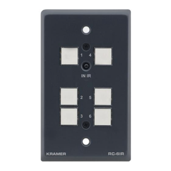
This section describes each Universal Room Controller as follows: the RC-8IR (see section 4.2), the RC-8 (see section 4.2), the RC-6IR (see section 4.3) and the RC-6 (see section 4.4). 4.1 Your RC-8IR Figure 1 and Table 1 define the RC-8IR front panel and right side panel:... -
Page 6: Figure 2: Rc-8Ir Rear Panel
1 These screws should not be removed during or after mounting 2 See the examples in Figure 3 3 Including the factory default IP number: 192.168.1.39 (an IP number is a device' s numerical address as expressed in the format specified in the Internet Protocol) KRAMER: SIMPLE CREATIVE TECHNOLOGY... -
Page 7: Your
Table 3 defines 1 Item 4 in Table 1 2 From this section on, all the information is relevant to the RC-6, RC-8, RC-6IR and RC-8IR units, unless noted otherwise 3 By authorized Kramer technical personnel or by an external system integrator 4 Refer to the separate online guide at http://www.kramerelectronics.com... -
Page 8: Figure 3: Example Of A Typical Rc-8Ir Configuration
Using Your Universal Room Controller DVD Player Video Player Lighting System Figure 3: Example of a Typical RC-8IR Configuration KRAMER: SIMPLE CREATIVE TECHNOLOGY... -
Page 9: Figure 4: Example Of A Typical Rc-8Ir Setup In The Lecture Auditorium
Introduction Table 3: Connection Scheme (for the example in Figure 3) This connector: Controls: RELAY2 The lights RELAY1 The screen RS-485 Terminal Block Connector A power amplifier (and speakers) RS-232 (TX1, RX1) Terminal Block Connector A projector IR OUT1 PIN A DVD player IR OUT2 PIN A video player... -
Page 10: Operating The Rc-8Ir
1 This is only one example among numerous possibilities, each button can be configure as required 2 By the technical installer 3 A macro sequence, including up to 15 commands per button, carried out one after the other KRAMER: SIMPLE CREATIVE TECHNOLOGY... -
Page 11: An Example Of Operating The Rc-8Ir
Thus each button will be assigned an identification number, see the example illustrated in Figure 7: Figure 7: Assigned Button Numbers 1 On the RC-6 and the RC-6IR, buttons 3 and 4 do not exist... -
Page 12: Using The Macro Buttons
2 Six times per second, as compared with twice per second during normal operation 3 For example, a faulty DVD player 4 In this example, press the HELP DESK button 5 Including the button you kept pressed to stop the macro sequence KRAMER: SIMPLE CREATIVE TECHNOLOGY... -
Page 13: Using The Internal Web Page
0.3 kg (0.67 lbs.) approx ACCESSORIES: Power supply, Java based control software (internal), Windows®-based Kramer control software OPTIONS: Dual IR emitter cable, single IR emitter cable, IR extension cable 1 The default IP number is 192.168.1.39, and may be changed by the system integrator... - Page 14 EXCLUSION OF DAMAGES The liability of Kramer for any effective products is limited to the repair or replacement of the product at our option. Kramer shall not be liable for: Damage to other property caused by defects in this product, damages based upon inconvenience, loss of use of the product, loss of time, commercial loss;...
- Page 15 For the latest information on our products and a list of Kramer distributors, visit our Web site: www.kramerelectronics.com, where updates to this user manual may be found. We welcome your questions, comments and feedback. Safety Warning: Disconnect the unit from the power supply before opening/servicing.
Need help?
Do you have a question about the RC-6 and is the answer not in the manual?
Questions and answers