
Related Manuals for Kramer RC-63DLN


Summary of Contents for Kramer RC-63DLN
-
Page 1: User Manual
K R A ME R E LE CT R O N IC S L TD . USER MANUAL MODEL: RC-63DLN Room Controller P/N: 2900-300317 Rev 1... -
Page 3: Table Of Contents
Figure 1: RC-63DLN Front Panel Figure 2: RC-63DLN Rear Panel for the USA Figure 3: RC-63DLN Rear Panel for Europe Figure 4: RC-63DLN European Version, Reset to Default Button Figure 5: Connecting the RC-63DLN Figure 6: K-NET PINOUT Connection Figure 7: Grounding Connection Components... -
Page 4: Introduction
Room Connectivity; GROUP 10: Accessories and Rack Adapters and GROUP 11: Sierra Video Products. Congratulations on purchasing your Kramer RC-63DLN Room Controller which is designed to let you remotely control an A/V system with ease, in a multimedia classroom or conference room. -
Page 5: Getting Started
Avoid interference from neighboring electrical appliances that may adversely influence signal quality Position your Kramer RC-63DLN away from moisture, excessive sunlight and dust This equipment is to be used only inside a building. It may only be connected to other equipment that is installed inside a building. -
Page 6: Recycling Kramer Products
Kramer Electronics has made arrangements with the European Advanced Recycling Network (EARN) and will cover any costs of treatment, recycling and recovery of waste Kramer Electronics branded equipment on arrival at the EARN facility. For details of Kramer’s recycling arrangements in your particular country go to our recycling pages at http://www.kramerelectronics.com/support/recycling/. -
Page 7: Overview
Overview The Kramer RC-63DLN is available as a 2 Gang wall plate for the USA or a 2 Gang wall plate for Europe. It features 6 front panel buttons designed in two groups; one group of 2 buttons, and another group of 4 buttons. Each group can be programmed according to the user's requirements. -
Page 8: The Rc-63Dln Room Controller Front Panel
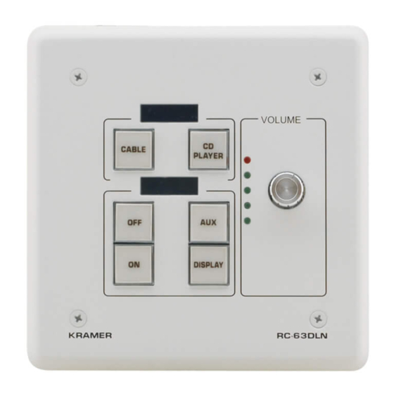
The RC-63DLN Room Controller Front Panel This section defines the front panel of the RC-63DLN. Figure 1: RC-63DLN Front Panel Feature Function 1 6 Configurable A 2-button group and a 4-button group. Function is programmed Buttons by the K-Config Configuration software... -
Page 9: The Rc-63Dln Room Controller Rear Panel
The RC-63DLN Room Controller Rear Panel This section defines the rear panel of the RC-63DLN. 3.2.1 The RC-63DLN Rear Panel Version for the USA This section shows the rear panel of the RC-63DLN USA version. Figure 2: RC-63DLN Rear Panel for the USA Feature Function... -
Page 10: Figure 3: Rc-63Dln Rear Panel For Europe
3.2.2 The RC-63DLN Rear Panel Version for Europe This section shows the rear panel of the RC-63DLN European version. Section 3.2.3 defines the Reset to Default button. Figure 3: RC-63DLN Rear Panel for Europe... -
Page 11: Figure 4: Rc-63Dln European Version, Reset To Default Button
Figure 4 shows the location of the Reset to Default button: Figure 4: RC-63DLN European Version, Reset to Default Button Feature Function Grounding Screw Connect to grounding wire (optional), see Section 4.3 RELAY Ports 2 relay connections (REL 1 and REL 2). Connect to room items... - Page 12 KNET ID auxiliary setting (ID=2). This operation should be carried out by authorized Kramer technical personnel or by a qualified system integrator. You can access the button by removing the volume control knob, unscrewing the 4 screws on the front panel and removing it.
-
Page 13: Connecting The Rc-63Dln Room Controller
4. Connect the K-NET ports to any RC devices with K-NET (for example, the Kramer RC-74DL and SL-12), see Section 4.2. Note that the RC-63DLN receives power over the K-NET port via the connected master room controller. Figure 5: Connecting the RC-63DLN RC-63DLN - Connecting the RC-63DLN Room Controller... -
Page 14: Connecting Rs-232 Devices
You can control an AV device such as a projector by connecting them to the RC-63DLN via their RS-232 connection. To connect a device to the RC-63DLN via RS-232: Using a straight cable, connect pin 2 to TX, pin 3 to RX and pin 5 to GND on... - Page 15 2. Insert the M3x6 screw through the toothed lock washers and the tongue terminal in the order shown above. 3. Insert the M3x6 screw (with the two toothed lock washers and ring tongue terminal) into the grounding screw hole and tighten the screw. RC-63DLN - Connecting the RC-63DLN Room Controller...
-
Page 16: Operating The Rc-63Dln
Operating the RC-63DLN You can operate your RC-63DLN via the front panel buttons or remotely by AUX. keypad over K-NET. The front panel buttons are configured using the K-Config software. For instructions on using the software, see the K-Config Software Guide available from our Web site www.kramerelectronics.com. -
Page 17: Front Panel Button Caps And Labels
Front Panel Button Caps and Labels The RC-63DLN is supplied with a button label sheet and 16 clear, button caps to house the labels. Figure 8 illustrates a sample button label sheet. RC-63DLN - Front Panel Button Caps and Labels... - Page 18 RC-63DLN – Front Panel Button Caps and Labels...
-
Page 19: Figure 8: Sample Button Label Sheet
Figure 8: Sample Button Label Sheet RC-63DLN - Front Panel Button Caps and Labels... -
Page 20: Installing The Front Panel Button Caps And Labels
Figure 10: Placing the Button Cap (Left – EU version, Right – US version) 5. Repeat for all caps (“OFF” horizontally oriented for USA, “ON” vertically oriented for Europe). 6. Remove the protective foils from both sides of the Perspex (acrylic glass) windows. RC-63DLN – Front Panel Button Caps and Labels... - Page 21 7. Place the faceplate on the RC-63DLN so that the four screw mounting holes are aligned. 8. Insert the four mounting screws and tighten with a screwdriver. 9. Install the volume control knob. RC-63DLN - Front Panel Button Caps and Labels...
-
Page 22: Technical Specifications
European version (80cm): 15.2cm x 1.9cm x 8cm (5.98" x 0.75" x 3.39", W, D, H) WEIGHT: 0.14kg. (0.31lbs.) approx. ACCESSORIES: Power supply Specifications are subject to change without notice Go to our Web site at http://www.kramerelectronics.com to access the list of resolutions RC-63DLN – Technical Specifications... - Page 24 For the latest information on our products and a list of Kramer distributors, visit our Web site where updates to this user manual may be found. We welcome your questions, comments, and feedback. Web site: www.kramerelectronics.com E-mail: info@kramerel.com SAFETY WARNING...
Need help?
Do you have a question about the RC-63DLN and is the answer not in the manual?
Questions and answers