
Related Manuals for Kramer RC-8IR


Summary of Contents for Kramer RC-8IR
- Page 1 Vertrieb von CAMBOARD Electronics Kramer Electronics, Ltd. USER MANUAL Model: RC-8IR Universal Room Controller www.camboard.de Tel. 07131 911201 ce-info@camboard.de Fax 07131 911203...
-
Page 2: Table Of Contents
Figure 6: Mounting the Device Housing Figure 7: Mounting the Faceplate Figure 8: Example of a Typical RC-8IR Configuration Figure 9: Example of a Typical RC-8IR Setup in the Lecture Auditorium Figure 10: RC-8IR Labels Setup Figure 11: RC-8IR Operation Example... - Page 3 Table 2: RC-8IR Right Side Panel Features Table 3: RC-8IR and Rear Panel Features Table 4: Connection Scheme (for the example in Figure 8) Table 5: The Commands Configuration Table 6: Technical Specifications of the RC-8IR Universal Room Controller www.camboard.de Tel. 07131 911201 ce-info@camboard.de...
-
Page 4: Introduction
3 That provides information about how to set up the system. This online guide may well be updated on a regular basis. For the latest online guide, go to http://www.kramerelectronics.com 4 The complete list of Kramer cables is on our Web site at http://www.kramerelectronics.com www.camboard.de Tel. -
Page 5: Overview
Kramer RC-8IR away from moisture, excessive sunlight and dust 1 Of up to five machines with unique IP addresses 2 Six buttons for RC-6IR, and eight buttons for the RC-8IR 3 To be configured by the system integrator only www.camboard.de... -
Page 6: Your Universal Room Controller
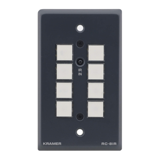
Figure 1 Table 2 Front Panel with Faceplate Front Panel without Faceplate Figure 1: RC-8IR Front Panel Table 1: RC-8IR Front Panel Features Feature Function Faceplate Attachment Holes Use to attach the faceplate to the device housing (see Table IR IN Receiver... -
Page 7: Figure 2: Rc-8Ir Right Side Panel
Figure 2 Table 2 Front Panel Buttons Figure 2: RC-8IR Right Side Panel Table 2: RC-8IR Right Side Panel Features Feature Function Housing and Faceplate Support Device housing supports the faceplate RELAY2 Connect each relay to a room item (such as lighting, screen... -
Page 8: Installing The Rc-8Ir Universal Room Controller
Grounding Screw Connect to grounding wire Installing the RC-8IR Universal Room Controller This section describes the installation of the RC-8IR and includes: • Setting up the labels on the buttons, according to your specific requirements • Mounting the RC-8IR device to the wall •... -
Page 9: Setting The Labels And Button Caps
Vertrieb von CAMBOARD Electronics Installing the RC-8IR Universal Room Controller 5.1 Setting the Labels and Button Caps To install the labels and button caps: 1. Remove the required labels from the supplied button label sheet. 2. Hold the button cap so that it is oriented as shown in... -
Page 10: Mounting The Device Housing
Figure 6: Figure 6: Mounting the Device Housing 5.3 Mounting the RC-8IR Faceplate 1. Place the faceplate on the RC-8IR so that the two screw mounting holes are aligned (see Figure 2. Insert the two mounting screws and tighten with a screwdriver. -
Page 11: Using The Rc-8Ir Universal Room Controller
2 Refer to the separate online “RC Configuration and Installation Guide” at http://www.kramerelectronics.com 3 Your RC-8IR was installed and configured to suit your specific requirements. This example describes how to setup one of an unlimited number of available setups for the system www.camboard.de... -
Page 12: Figure 9: Example Of A Typical Rc-8Ir Setup In The Lecture Auditorium
VCR, a DVD and an amplifier inside, are all controlled via the RC-8IR. The presenter’s laptop is located on the podium, next to where the RC-8IR is mounted. It is also controlled by the RC-8IR and is used for presentations, slide shows and so on. -
Page 13: Operating The Rc-8Ir
Vertrieb von CAMBOARD Electronics Using the RC-8IR Universal Room Controller 6.1 Operating the RC-8IR In the following example that is illustrated in Figure 10 , the RC-8IR is labeled with specific functions and each button is programmed to perform... -
Page 14: An Example Of Operating The Rc-8Ir
Vertrieb von CAMBOARD Electronics Using the RC-8IR Universal Room Controller 6.2 An Example of Operating the RC-8IR Figure 11 shows an operating example: Figure 11: RC-8IR Operation Example www.camboard.de Tel. 07131 911201 ce-info@camboard.de Fax 07131 911203... -
Page 15: Using The Macro Buttons
To turn off the backlight, press the respective buttons once again. 6.6 Using the Internal Web Page The internal Web page can be used to remotely operate the RC-8IR via the Ethernet. To control your RC-8IR via the internal Web page, do the following:... -
Page 16: Flash Memory Upgrade
Type the unit’s IP number in the Address bar of your browser (or type any link defined by the system integrator). The RC-8IR front panel is displayed on your screen (see Figure 12 2. Press the on-screen buttons to control the unit. -
Page 17: Connecting The Pc To The Rs-232 Port
Before installing the latest Kramer Ethernet firmware version on the RC-8IR, do the following: 1. Connect the RS-232 port (COM 1) on the RC-8IR to a Null-modem adapter and connect the Null-modem adapter with a 9-wire flat cable to the RS-232 9-pin D-sub COM port on your PC. -
Page 18: Installing The Web Applet
M3x5 screws, Java based control software (internal), Windows®-based Kramer control software OPTIONS: Kramer 3.5mm to IR Emitter Control Cable (C-A35/IRE-10), 15 meter and 20 meter IR emitter extension cables 1 This section is applicable only to firmware version 26.0 and higher and requires RC Configuration Software version 1.26.0.38 and higher... - Page 19 EXCLUSION OF DAMAGES The liability of Kramer for any effective products is limited to the repair or replacement of the product at our option. Kramer shall not be liable for: 1. Damage to other property caused by defects in this product, damages based upon inconvenience, loss of use of the product, loss of time, commercial loss;...
- Page 20 Vertrieb von CAMBOARD Electronics For the latest information on our products and a list of Kramer distributors, visit our Web site: www.kramerelectronics.com, where updates to this user manual may be found. We welcome your questions, comments and feedback. Safety Warning: Disconnect the unit from the power supply before opening/servicing.
Need help?
Do you have a question about the RC-8IR and is the answer not in the manual?
Questions and answers