
Related Manuals for Kramer RC-6IR


Summary of Contents for Kramer RC-6IR
-
Page 1: User Manual
Kramer Electronics, Ltd. USER MANUAL Models: RC-6IR, Universal Room Controller RC-8IR, Universal Room Controller... -
Page 2: Table Of Contents
Figure 9: The KFR-Programmer Window Tables Table 1: RC-8IR and RC-6IR Front Panel Features Table 2: RC-8IR and RC-6IR Right Side Panel Features Table 3: RC-8IR and RC-6IR Rear Panel Features Table 4: Connection Scheme (for the example in Figure 4) -
Page 3: Introduction
3 That provides information about how to set up the system. This online guide may well be updated on a regular basis. For the latest online guide, go to http://www.kramerelectronics.com 4 The complete list of Kramer cables is on our Web site at http://www.kramerelectronics.com... - Page 4 IR remote control unit Macro mode operation, for programming up to 15 commands with the press of a single button. The RC-6IR (with six buttons) has a total of 90 commands and the RC-8IR (with eight buttons) has a total of 120...
-
Page 5: Your Universal Room Controller
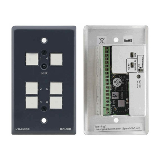
Your Universal Room Controller Your Universal Room Controller Figure 1 and Table 2 define the RC-8IR and the RC-6IR front panels: Figure 1: RC-8IR and RC-6IR Front Panels Table 1: RC-8IR and RC-6IR Front Panel Features Feature Function Mounting holes (2) -
Page 6: Figure 2: Rc-8Ir And Rc-6Ir Right Side Panel
Your Universal Room Controller Figure 2 and Table 2 define the RC-8IR and the RC-6IR right side panel: Front Panel Buttons Figure 2: RC-8IR and RC-6IR Right Side Panel Table 2: RC-8IR and RC-6IR Right Side Panel Features Feature Function... -
Page 7: Using Your Universal Room Controller
1 Including the factory default IP number: 192.168.1.39 (an IP number is a device' s numerical address as expressed in the format specified in the Internet Protocol) 2 From this section on, all the information is relevant to the RC-6IR and RC-8IR units, unless noted otherwise 3 By authorized Kramer technical personnel or by an external system integrator 4 Refer to the separate online “RC Configuration and Installation Guide”... -
Page 8: Figure 4: Example Of A Typical Rc-8Ir Configuration
Using Your Universal Room Controller DVD Player Video Player Lighting System Figure 4: Example of a Typical RC-8IR Configuration KRAMER: SIMPLE CREATIVE TECHNOLOGY... -
Page 9: Figure 5: Example Of A Typical Rc-8Ir Setup In The Lecture Auditorium
Using Your Universal Room Controller Table 4: Connection Scheme (for the example in Figure 4) This connector: Controls: RELAY2 The lights RELAY1 The screen RS-485 Terminal Block Connector A power amplifier (and speakers) RS-232 (TX1, RX1) Terminal Block Connector A projector IR OUT1 PIN A DVD player IR OUT2 PIN... -
Page 10: Operating The Rc-8Ir
1 This is only one example among numerous possibilities, each button can be configured as required 2 By the technical installer 3 A macro sequence, including up to 15 commands per button, carried out one after the other KRAMER: SIMPLE CREATIVE TECHNOLOGY... -
Page 11: An Example Of Operating The Rc-8Ir
Using Your Universal Room Controller 5.2 An Example of Operating the RC-8IR Figure 7 shows an operating example: turn off the lights DOWN Figure 7: RC-8IR Operation Example... -
Page 12: Using The Macro Buttons
On the RC-8IR: press and hold buttons 4 and 8 simultaneously for about 2 seconds On the RC-6IR: press and hold buttons 3 and 6 simultaneously for about 2 seconds All the buttons blink momentarily and the panel is locked. -
Page 13: Using The Internal Web Page
Figure 8: Internal Web Page Front Panel Flash Memory Upgrade The RC device firmware is located in FLASH memory, which lets you upgrade to the latest Kramer firmware version in minutes! The process involves: Downloading the upgrade package from the Internet (see section 6.1) Connecting the PC to the RS-232 port (see section 6.2) -
Page 14: Connecting The Pc To The Rs-232 Port
3. Install the KFR-Programmer Application. Connecting the PC to the RS-232 Port Before installing the latest Kramer Ethernet firmware version on the RC-8IR, do the following: 1. Connect the RS-232 port (COM 1) on the RC-8IR to a Null-modem adapter and connect the Null-modem adapter with a 9-wire flat cable to the RS-232 9-pin D-sub COM port on your PC. -
Page 15: Installing The Web Applet
M3x5 screws, Java based control software (internal), Windows®-based Kramer control software OPTIONS: Kramer 3.5mm to IR Emitter Control Cable (C-A35/IRE-10), 15 meter and 20 meter IR emitter extension cables 1 To which the RC device is connected on your PC 2 This section is applicable only to firmware version 26.0 and higher and requires RC Configuration Software version... - Page 16 EXCLUSION OF DAMAGES The liability of Kramer for any effective products is limited to the repair or replacement of the product at our option. Kramer shall not be liable for: 1. Damage to other property caused by defects in this product, damages based upon inconvenience, loss of use of the product, loss of time, commercial loss;...
- Page 17 For the latest information on our products and a list of Kramer distributors, visit our Web site: www.kramerelectronics.com, where updates to this user manual may be found. We welcome your questions, comments and feedback. Safety Warning: Disconnect the unit from the power supply before opening/servicing.
Need help?
Do you have a question about the RC-6IR and is the answer not in the manual?
Questions and answers