
Subscribe to Our Youtube Channel
Related Manuals for Kramer RC-13TC


Summary of Contents for Kramer RC-13TC
- Page 1 K R A ME R E LE CT R O N IC S L T D . USER MANUAL MODEL: RC-13TC Video Transport Controller P/N: 2900-000648 Rev 2...
-
Page 2: Table Of Contents
F igure 3: Sample RC-13TC Standalone Video Transport Controller Configuration F igure 4: RC-13TC Standalone Power Supply Connection F igure 5: RC-13TC Connections when used as part of a K-NET System F igure 6: RC-13TC LCD Programmed with Text F igure 7: Grounding Connection Components... -
Page 3: Introduction
Introduction Welcome to Kramer Electronics! Since 1981, Kramer Electronics has been providing a world of unique, creative, and affordable solutions to the vast range of problems that confront the video, audio, presentation, and broadcasting professional on a daily basis. In recent years, we have redesigned and upgraded... -
Page 4: Getting Started
• Avoid interference from neighboring electrical appliances that may adversely influence signal quality • Position your Kramer RC-13TC away from moisture, excessive sunlight and dust Caution: No operator serviceable parts inside the unit Warning: Disconnect the power and unplug the unit from the wall... -
Page 5: Overview
Overview This user manual descr bes the RC-13TC Video Transport Controller. The RC-13TC controller interface acts as an all-in-one, remote control panel for several AV sources in any venue, such as, classrooms, boardrooms or auditoriums. The RC-13TC streamlines operations by enabling remote transport control of the video source in the room. -
Page 6: Defining The Rc-13Tc Video Transport Controller
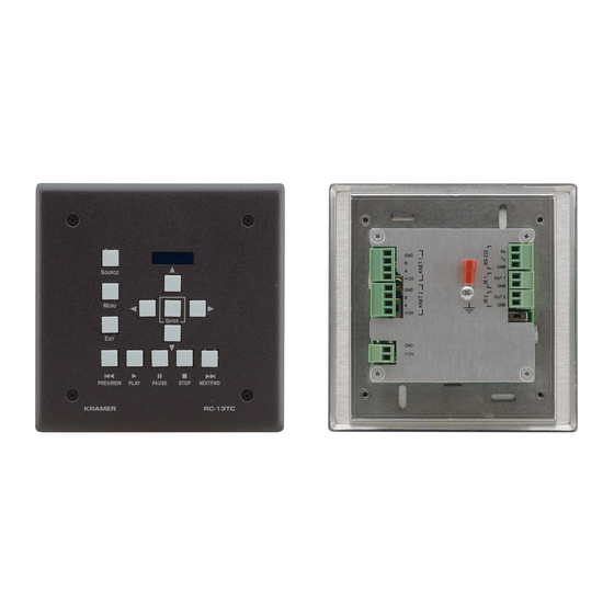
Defining the RC-13TC Video Transport Controller This section defines the RC-13TC. Figure 1: RC-13TC Video Transport Controller Front Panel Feature Function Source Select Button Press to select the AV source Video Transport Control Buttons Use to control the functions of the selected AV... -
Page 7: F Igure 2: Rc-13Tc Video Transport Controller Rear Panel
Figure 2: RC-13TC Video Transport Controller Rear Panel Feature Function KNET TERM Termina ion Switch Use to set the K-NET bus termination (see Section 5.2.2 KNET 4-pin Removable Terminal Connect to a master room controller or to another Blocks (1 and 2) auxiliary device. -
Page 8: Using Your Video Transport Controller
Programming the LCD readout using K-Config Configuration software (described in the K-Config Configuration Guide) • Programming the button actions using K-Config Configuration software The RC-13TC as a Standalone Video Transport Controller Figure 3: Sample RC-13TC Standalone Video Transport Controller Configuration RC-13TC - Using Your Video Transport Controller... -
Page 9: F Igure 4: Rc-13Tc Standalone Power Supply Connection
Display or switcher 5.1.2 Connecting a Standalone RC-13TC to a Power Supply When the RC-13TC is employed as a standalone room controller it should be connected to the power supply as illustrated in Figure Figure 4: RC-13TC Standalone Power Supply Connection... -
Page 10: The Rc-13Tc As An Auxiliary Control Panel
The RC-13TC as an Auxiliary Control Panel When the RC-13TC is used as an auxiliary control panel, as illustrated in Figure • It requires only a K-NET connection to another auxiliary device • A power supply unit is not required as the K-Net connection carries the power supply Power supplies are sold separately. -
Page 11: Operating The Rc-13Tc Video Transport Controller
The factory default is down (terminated). Operating the RC-13TC Video Transport Controller The RC-13TC is delivered with no button functions preprogrammed. For the buttons to perform any functions, they must be programmed first. Once a button is programmed to suit the source or display that is connected, the... -
Page 12: Grounding The Rc-13Tc Video Transport Controller
2. Insert the M3x6 screw through the toothed lock washers and the tongue terminal in the order shown above. 3. Insert the M3x6 screw (with the two toothed lock washers and ring tongue terminal) into the grounding screw hole and tighten the screw. RC-13TC - Grounding the RC-13TC Video Transport Controller... -
Page 13: Mounting The Faceplate
To mount the faceplate: 1. Remove the protective foil from the outside of the LCD acrylic window. 2. Position the faceplate on the RC-13TC so that the four screw mounting holes are aligned. 3. Insert the four M3x4mm mounting screws and tighten them with a screwdriver. -
Page 14: Technical Specifications
0.3kg (0.66lbs) approx. ACCESSORIES: USB cable 3' (0.91m) (P/N: C-UA/MUB-3), screwdriver, power supply, IR emitter control cable (P/N: C-A35/IRE- 10), Windows®-based Kramer control software, four M3x4mm flat-head screws OPTIONS: 15m and 20m IR emitter extension cables Specifications are subject to change without notice at http://www.kramerelectronics.com... - Page 16 For the latest information on our products and a list of Kramer distributors, visit our Web site where updates to this user manual may be found. We welcome your questions, comments, and feedback. Web site: www.kramerelectronics.com E-mail: info@kramerel.com SAFETY WARNING...
Need help?
Do you have a question about the RC-13TC and is the answer not in the manual?
Questions and answers