Table of Contents
Advertisement
Quick Links
Download this manual
See also:
User Manual
Advertisement
Table of Contents

Related Manuals for Kramer RC-74DL


Summary of Contents for Kramer RC-74DL
- Page 1 Kramer Electronics, Ltd. USER MANUAL Model: RC-74DL Master Room Controller...
-
Page 2: Table Of Contents
Figure 8: Button Cap Orientation with Label Figure 9: Placing the Button Cap Tables Table 1: RC-74DL Master Room Controller Front Panel Features Table 2: RC-74DL Master Room Controller Rear Panel Features Table 3: Grounding Component Descriptions Table 4: RC-74DL Master Room Controller Technical Specifications... -
Page 3: Introduction
• Review the contents of this user manual • Use Kramer high-performance high-resolution cables Overview The RC-74DL is a highly versatile, 3 gang US, master room controller that acts as an all-in-one extended remote control panel for control of AV equipment—especially projectors and associated equipment—in any room (such as classrooms, boardrooms, or auditoriums). - Page 4 • Avoid interference from neighboring electrical appliances and position your RC-74DL away from moisture, excessive sunlight and dust 1 Available from Kramer Electronics on our Web site at http://www kramerelectronics com/support/?soft=k-config 2 K-NET™ is a proprietary Kramer protocol for interconnecting Kramer units KRAMER: SIMPLE CREATIVE TECHNOLOGY...
-
Page 5: Defining The Rc-74Dl Master Room Controller
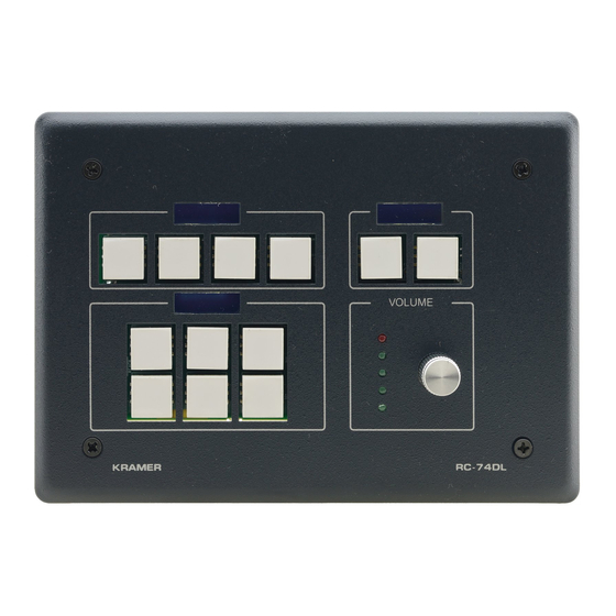
Figure 1 Table 1 define the front panel of the RC-74DL. Figure 1: RC-74DL Master Room Controller Front Panel Table 1: RC-74DL Master Room Controller Front Panel Features Feature Function 6 Configurable Button Switches Function is programmed by the K-Config Configuration... -
Page 6: Figure 2: Rc-74Dl Master Room Controller Rear Panel
Defining the RC-74DL Master Room Controller Figure 2 Table 2 define the rear panel of the RC-74DL. Figure 2: RC-74DL Master Room Controller Rear Panel KRAMER: SIMPLE CREATIVE TECHNOLOGY... -
Page 7: Table 2: Rc-74Dl Master Room Controller Rear Panel Features
Connect to IR emitter cables (from 1 to 2) 1 This operation should be carried out by authorized Kramer technical personnel or by an external system integrator, and requires removal of the device from the wall by unscrewing the four wall mount screws... -
Page 8: Connecting The Rc-74Dl Master Room Controller
6. Connect the K-NET port to any RC device with K-NET (for example, the RC-63DL). 1 Switch off the power on each device before connecting it to your RC-74DL After connecting your RC-74DL, switch on its power and then switch on the power to each device... -
Page 9: Figure 3: Connecting The Rc-74Dl Master Room Controller
Connecting the RC-74DL Master Room Controller Figure 3: Connecting the RC-74DL Master Room Controller... -
Page 10: Connecting The Rs-232 Interface
Site-CTRL control program. To connect the RC-74DL to a network: 1. Connect the Ethernet port of the RC-74DL to the Ethernet port on a network hub or network router, via a straight cable with RJ-45 connectors. 2. At the other end, connect the Internet to a PC running Site-CTRL. -
Page 11: Grounding The Rc-74Dl Master Room Controller
Grounding the RC-74DL Master Room Controller Grounding the RC-74DL Master Room Controller The grounding screw is used to earth the chassis of the unit to the building ground preventing static electricity from impacting the performance of the unit. Figure 5 Table 3 defines the grounding screw components. -
Page 12: Front Panel Button Caps And Labels
Front Panel Button Caps and Labels Front Panel Button Caps and Labels The RC-74DL is supplied with a button label sheet and 12 clear, button caps to house the labels. Figure 6 illustrates a sample button label sheet. KRAMER: SIMPLE CREATIVE TECHNOLOGY... - Page 13 Front Panel Button Caps and Labels...
-
Page 14: Figure 6: Sample Button Label Sheet
Front Panel Button Caps and Labels Figure 6: Sample Button Label Sheet KRAMER: SIMPLE CREATIVE TECHNOLOGY... -
Page 15: Installing The Front Panel Button Caps, Labels
6. Remove the protective foils from both sides of the Perspex (acrylic glass) windows. 7. Place the faceplate on the RC-74DL so that the four screw mounting holes are aligned. 8. Insert the four mounting screws and tighten with a screwdriver. -
Page 16: Technical Specifications
The RC-74DL technical specifications are shown in Table 4 Table 4: RC-74DL Master Room Controller Technical Specifications INPUTS: 3 RS-232, 1 RS-485, 2 GPI/O and 2 K-NET on terminal block connectors; Ethernet on an RJ-45 connector; 1 infrared sensor, 1 USB... - Page 17 1. Any product which is not distributed by us or which is not purchased from an authorized Kramer dealer. If you are uncertain as to whether a dealer is authorized, please contact Kramer at one of the agents listed in the Web site www.kramerelectronics com.
- Page 18 For the latest information on our products and a list of Kramer distributors, visit our Web site www.kramerelectronics.com where updates to this user manual may be found. We welcome your questions, comments and feedback. Safety Warning: Disconnect the unit from the power supply before opening/servicing.
Need help?
Do you have a question about the RC-74DL and is the answer not in the manual?
Questions and answers