Advertisement
Quick Links
Advertisement

Subscribe to Our Youtube Channel
Related Manuals for Clarke CBS225


Summary of Contents for Clarke CBS225
- Page 1 9”BANDSAW MODEL NO: CBS225 PART NO: 6460133 OPERATION & MAINTENANCE INSTRUCTIONS GC0816...
- Page 2 GUARANTEE This CLARKE product is guaranteed against faulty manufacture for a period of 12 months from the date of purchase. Please keep your receipt as proof of purchase.
- Page 3 SAFETY WARNINGS CAUTION: FAILURE TO FOLLOW THESE PRECAUTIONS COULD RESULT IN PERSONAL INJURY, AND/OR DAMAGE TO PROPERTY. WORK ENVIRONMENT 1. Keep the work area clean and well lit. Cluttered and dark areas invite accidents. 2. Do not operate power tools in explosive atmospheres, such as in the presence of flammable liquids, gases or dust.
- Page 4 2. This machine is designed for indoor environments and must not be used for other purposes. 3. If the machine requires repair, always contact your Clarke dealer. Always insist on original spare parts. Repairs carried out by unauthorized persons may be dangerous and invalidate the guarantee.
- Page 5 POWER TOOL USE AND CARE 1. Do not force the machine. Use the correct power tool for your application. It will do a better and safer job at the rate for which it was designed. 2. Do not use the power tool if the switch does not turn it on and off. Any power tool that cannot be controlled with the switch is dangerous and must be repaired.
- Page 6 5. Never use damaged blades. (Replacement blades are available from your Clarke dealer. 6. Never attempt any maintenance or adjustments of the saw band when it is in motion. 7. Do not remove jammed cut -off pieces until the blade has stopped.
- Page 7 SPECIFICATIONS CBS225 Weight 21 kg Dimensions (W x D x H) 490 x 420 x 830 mm Table Size (W x D) 300 x 300 mm Throat Width 228 mm Table Tilt Angle 0 - 45 Mitre Gauge Range Left 60...
- Page 8 ELECTRICAL CONNECTIONS WARNING! Read these electrical safety instructions thoroughly before connecting the product to the mains supply. Before switching the product on, make sure that the voltage of your electricity supply is the same as that indicated on the rating plate. This product is designed to operate on 230VAC 50Hz.
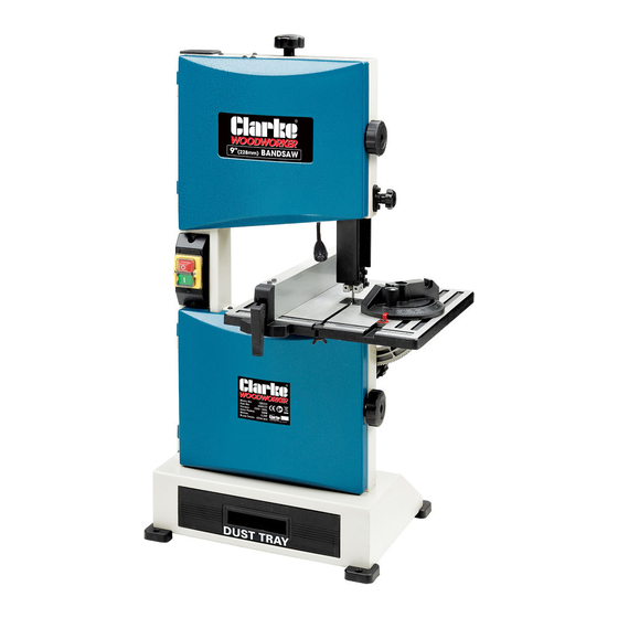
- Page 9 OVERVIEW DESCRIPTION DESCRIPTION Blade Tension Setting Knob Cover Release knob Guide Height Setting Knob Dust Tray Upper Blade Guide Start/Stop buttons Mitre Gauge Assembly Rip Fence Assembly Tilting Work Table Parts & Service: 020 8988 7400 / E-mail: Parts@clarkeinternational.com or Service@clarkeinternational.com...
- Page 10 CONTENTS Make sure that all parts are un-damaged and are present. If any parts are missing or damaged please contact your CLARKE dealer immediately. The following loose components are supplied with the bandsaw assembly. ITEM DESCRIPTION ITEM DESCRIPTION Bandsaw Assembly...
- Page 11 ASSEMBLY PREPARATION For maximum stability the bandsaw should be bolted firmly to either a workbench, a suitable stand, or a piece of plywood, 5/8” thick, and the plywood should be clamped firmly to a workbench, using clamps, whenever the bandsaw is being used. The saw must be located in an area large enough to allow you to work freely, taking into account the likely size of your workpiece, and that there should be adequate lighting.
- Page 12 8. Fit the rip fence to the table if required. 9. Slide the mitre gauge into the slot in the table if required. ADJUSTING THE COMPONENTS TILTING THE TABLE 1. Loosen the locking handle and turn the table tilting knob to adjust the table to the desired angle.
- Page 13 TRACKING THE SAW BLADE 1. Open the upper and lower covers by releasing the twist knobs. 2. Manually rotate the upper wheel, taking care of the sharp blade. If the saw blade does not run on the centre of the rubber tyre the tracking needs to be corrected before use by adjusting the tilt angle of the upper bandsaw wheel.
- Page 14 BLADE GUIDES / BEARING SETTING The upper and lower blade guides need to be re-adjusted after any blade change or tracking adjustment. This task may be easier if the table is tilted for better access. 1. Loosen the set-screws (A) and position the guide pins 0.5 mm from the blade.
- Page 15 UPPER BLADE GUIDE ADJUSTMENT The height of the upper blade guide needs to be adjusted prior to every cutting operation to accommodate the height of the workpiece. The upper blade guide should be set approx 3 mm above the workpiece. Set the upper blade guide by turning the adjusting knob to the desired height and securing in position with...
- Page 16 USING THE MITRE GAUGE The mitre gauge is inserted into the table slot from either edge. 1. To set a mitre angle, loosen the lock knob by turning it counter- clockwise. • The mitre gauge can be turned to max 60 in both directions.
- Page 17 USING THE PUSH STICK The push-stick serves as an extension of the operators hand as protection against accidentally touching the saw blade. The push-stick should be used if the rip fence is close to the blade. When not in use, the push-stick can be stored on the hook provided on the bandsaw frame.
- Page 18 TYPES OF CUT Several types of cut are possible with this saw i.e. rip cutting, cross cutting, bevel or mitre cutting. RIP CUTTING This term refers to cutting timber in the same direction as the grain, rather than across it. You can rip wood freehand to a drawn pencil line, but best results are obtained by using the rip fence.
- Page 19 When freehand cutting, always feed the work slowly so that the blade can follow the line you wish to cut. Make sure not to drag the work off line, forcing the blade sideways, or twisting it. In many cases, it is helpful to rough cut about 6mm away from the line. For difficult curves which may be too tight for the blade, make relief cuts at 90°...
- Page 20 MAINTENANCE WARNING: ALWAYS SWITCH OFF THE MACHINE AND DISCONNECT FROM THE POWER SUPPLY BEFORE CARRYING OUT ANY CLEANING OR MAINTENANCE TASKS. CLEANING Accumulated dust and chips should be removed from inside the bandsaw frequently as well as emptying the dust drawer. Open the upper and lower covers, use a soft brush and/or vacuum cleaner to remove sawdust.
- Page 21 Cover the machine with a plastic bag and store it in a dry location. OPTIONAL ACCESSORIES REPLACEMENT BLADES Suitable blades are available from your Clarke stockist: • 6tpi Bandsaw blade: Part No6458005 • 10tpi Bandsaw blade: Part No6458000 DUST EXTRACTORS A choice of dust extractors is available for this bandsaaw including CDE35 Portable Dust Extractor &...
- Page 22 7. Blade is badly welded or 7. Renew blade brazed. 8. Fit only quality blades 8. Wrong blade fitted. supplied by your Clarke dealer. 9. Bandsaw left running when 9. Always switch machine not in use. off when not in use.
- Page 23 PARTS DIAGRAM Parts & Service: 020 8988 7400 / E-mail: Parts@clarkeinternational.com or Service@clarkeinternational.com...
- Page 24 PARTS LIST PART NO DESCRIPTION PART NO DESCRIPTION Blade tension knob Cover Flat washer 8 mm Interlock switch Blade tension spring Interlock switch box Carriage bolt M8 x 80 Nut M4 Pulling plate Frame Socket head screw M5x8 Switch box Shaft Connecting terminal Lock Catch...
- Page 25 PARTS LIST PART NO DESCRIPTION PART NO DESCRIPTION Catching knob Socket head screw M5x10 Socket head screw M6x16 Locking knob Socket head screw Flat washer 8mm Bearing 606-ZZ Spring Flat washer 5mm Tracking knob Support rod Socket head screw M6x16 Socket head screw M5x14 Release block Bearing 605ZZ...
- Page 26 PARTS LIST PART NO DESCRIPTION PART NO DESCRIPTION Motor Hex wrench 4mm, 6mm Sponge ring Push stick Motor pulley Hook Flat washer 5mm Hex nut Socket head screw M6x12 Rip fence assembly Flat washer 8mm Socket head screw M8x25 Power cable Inner wiring Protective sleeve Spanner...
- Page 27 DECLARATION OF CONFORMITY Parts & Service: 020 8988 7400 / E-mail: Parts@clarkeinternational.com or Service@clarkeinternational.com...
Need help?
Do you have a question about the CBS225 and is the answer not in the manual?
Questions and answers