
Related Manuals for HP 34401A


Summary of Contents for HP 34401A
- Page 1 User’s Guide Part Number 34401-90004 February 1996 For Safety information, Warranties, and Regulatory information, see the pages behind the Index. © Copyright Hewlett-Packard Company 1991, 1996 All Rights Reserved. HP 34401A Multimeter...
- Page 2 Portable, ruggedized case with non-skid feet Flexible System Features HP-IB (IEEE-488) interface and RS-232 interface Standard programming languages: SCPI, HP 3478A, and Fluke 8840 Reading rates up to 1000 readings per second Storage for up to 512 readings Limit testing with pass/fail signals Optional HP 34812A BenchLink/Meter Software ®...
-
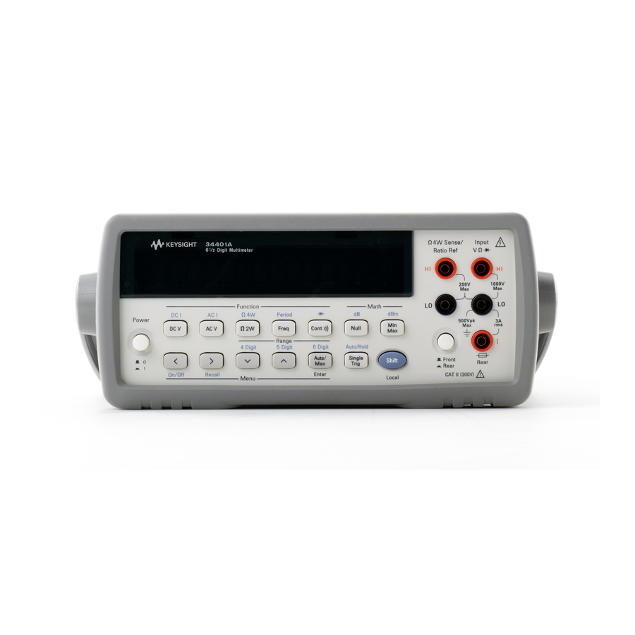
Page 3: The Front Panel At A Glance
The Front Panel at a Glance Measurement Function keys Front / Rear Input Terminal Switch Math Operation keys Range / Number of Digits Displayed keys Single Trigger / Autotrigger / Reading Hold key Menu Operation keys Shift / Local key... - Page 4 4: TEST 5: DISPLAY 6: BEEP 7: COMMA 8: REVISION E: Input / Output MENU ’ ’ ’ ’ 1: HP-IB ADDR 2: INTERFACE 3: BAUD RATE 4: PARITY 5: LANGUAGE F: CALibration MENU* ’ ’ ’ ’ 1: SECURED...
- Page 5 Display Annunciators Turns on during a measurement. Adrs Multimeter is addressed to listen or talk over the HP-IB interface. Multimeter is in remote mode (remote interface). Multimeter is using manual ranging (autorange is disabled). Trig Multimeter is waiting for a single trigger or external trigger.
-
Page 6: Chassis Ground
Front and Rear Current Input Fuse RS-232 interface connector Use the front-panel Input / Output Menu to: Select the HP-IB or RS-232 interface (see chapter 4). Set the HP-IB bus address (see chapter 4). Set the RS-232 baud rate and parity (see chapter 4). -
Page 7: In This Book
1-800-452-4844 in the United States, or contact your nearest Hewlett-Packard Sales Office. If your HP 34401A fails within three years of purchase, HP will repair or replace it free of charge. Call 1-800-258-5165 (“Express Exchange”) in the United States, or contact your nearest Hewlett-Packard Sales Office. -
Page 8: Table Of Contents
Contents Chapter 1 Quick Start To Prepare the Multimeter for Use 13 If the Multimeter Does Not Turn On 14 To Adjust the Carrying Handle 16 To Measure Voltage 17 To Measure Resistance 17 To Measure Current 18 To Measure Frequency (or Period) 18 To Test Continuity 19 To Check Diodes 19 To Select a Range 20... - Page 9 Display Control 87 Beeper Control 88 Comma Separators 89 Firmware Revision Query 89 SCPI Language Version Query 90 Remote Interface Configuration HP-IB Address 91 Remote Interface Selection 92 Baud Rate Selection (RS-232) 93 Parity Selection (RS-232) 93 Programming Language Selection 94 Calibration...
- Page 10 An Introduction to the SCPI Language 154 Output Data Formats 159 Using Device Clear to Halt Measurements 160 TALK ONLY for Printers 160 To Set the HP-IB Address 161 To Select the Remote Interface 162 To Set the Baud Rate 163 To Set the Parity 164...
- Page 11 Contents Chapter 7 Measurement Tutorial Thermal EMF Errors 199 Loading Errors (dc volts) 199 Leakage Current Errors 199 Rejecting Power-Line Noise Voltages 200 Common Mode Rejection (CMR) 201 Noise Caused by Magnetic Loops 201 Noise Caused by Ground Loops 202 Resistance Measurements 203 4-Wire Ohms Measurements 203 Removing Test Lead Resistance Errors 204...
-
Page 12: Chapter 1 Quick Start
Quick Start... -
Page 13: Quick Start
Quick Start One of the first things you will want to do with your multimeter is to become acquainted with its front panel. We have written the exercises in this chapter to prepare the multimeter for use and help you get familiar with some of its front-panel operations. -
Page 14: To Prepare The Multimeter For Use
The front-panel display will light up while the multimeter performs its power-on self-test. The bus address is displayed. Notice that the HP-IB multimeter powers up in the dc voltage function with autoranging enabled. To review the power-on display with all annunciators turned on, hold down as you turn on the multimeter. -
Page 15: Power-Line Voltage Setting
See the next page if you need to replace the power-line fuse. To replace the 250 mAT fuse, order HP part number 2110-0817. To replace the 125 mAT fuse, order HP part number 2110-0894. - Page 16 Remove the line-voltage selector from fuse-holder assembly from the rear panel. the assembly. See rear panel for proper fuse rating . HP Part Number: 2110-0817 (250 mAT) 2110-0894 (125 mAT) Rotate the line-voltage selector until the Replace the fuse-holder assembly in correct voltage appears in the window.
-
Page 17: To Adjust The Carrying Handle
Chapter 1 Quick Start To Adjust the Carrying Handle To Adjust the Carrying Handle To adjust the position, grasp the handle by the sides and pull outward. Then, rotate the handle to the desired position. Bench-top viewing positions Carrying position... -
Page 18: To Measure Voltage
Chapter 1 Quick Start To Measure Voltage To Measure Voltage Ranges: 100 mV, 1 V, 10 V, 100 V, 1000 V (750 Vac) Maximum resolution: 100 nV (on 100 mV range) AC technique: true , ac-coupled To Measure Resistance Ranges: 100 1 k , 10 k , 100 k , 1 M , 10 M , 100 M Maximum resolution: 100 (on 100 ohm range) -
Page 19: To Measure Current
Chapter 1 Quick Start To Measure Current To Measure Current Ranges: 10 mA (dc only), 100 mA (dc only), 1 A , 3 A Maximum resolution: 10 nA (on 10 mA range) AC technique: true , ac-coupled To Measure Frequency (or Period) Measurement band: 3 Hz to 300 kHz (0.33 sec to 3.3 sec) Input signal range: 100 mVac to 750 Vac Technique: reciprocal counting... -
Page 20: To Test Continuity
Chapter 1 Quick Start To Test Continuity To Test Continuity Test current source: 1 mA Maximum resolution: 0.1 (range is fixed at 1 kohm) Beeper threshold: 1 to 1000 (beeps below adjustable threshold) To Check Diodes Test current source: 1 mA Maximum resolution: 100 V (range is fixed at 1 Vdc) Beeper threshold: 0.3 volts 0.8 volts (not adjustable) -
Page 21: To Select A Range
Chapter 1 Quick Start To Select a Range To Select a Range You can let the multimeter automatically select the range using autoranging or you can select a fixed range using manual ranging. Selects a lower range and disables autoranging. Selects a higher range and Man annunciator is on when disables autoranging. -
Page 22: To Set The Resolution
Chapter 1 Quick Start To Set the Resolution To Set the Resolution You can set the display resolution to 4 , or 6 digits either to optimize measurement speed or noise rejection. In this book, the most significant digit (leftmost on the display) is referred to as the “ ”... -
Page 23: Front-Panel Display Formats
Chapter 1 Quick Start Front-Panel Display Formats Front-Panel Display Formats – Negative sign or blank (positive) “ ” digit (0 or 1) Numeric digits H.DDD,DDD EFFF Exponent ( m, k, M ) Measurement units ( VDC, OHM, HZ, dB ) Front-panel display format. -
Page 24: To Rack Mount The Multimeter
Instructions and mounting hardware are included with each rack-mounting kit. Any HP System II instrument of the same size can be rack-mounted beside the HP 34401A. Remove the carrying handle, and the front and rear rubber bumpers, before rack-mounting the multimeter. - Page 25 Chapter 1 Quick Start To Rack Mount the Multimeter To rack mount a single instrument, order adapter kit 5063-9240. To rack mount two instruments side-by-side, order lock-link kit 5061-9694 and flange kit 5063-9212. To install one or two instruments in a sliding support shelf, order shelf 5063-9255, and slide kit 1494-0015 (for a single instrument, also order filler panel 5002-3999).
-
Page 26: Chapter 2 Front-Panel Menu Operation
Front-Panel Menu Operation... - Page 27 Front-Panel Menu Operation By now you should be familiar with the FUNCTION RANGE / DIGITS groups of front-panel keys. You should also understand how to make front-panel connections for the various types of measurements. If you are not familiar with this information, we recommend that you read chapter 1, “Quick Start,”...
-
Page 28: Front-Panel Menu Reference
Chapter 2 Front-Panel Menu Operation Front-Panel Menu Reference Front-Panel Menu Reference A: MEASurement MENU ’ ’ ’ ’ 1: AC FILTER 2: CONTINUITY 3: INPUT R 4: RATIO FUNC 5: RESOLUTION 1: AC FILTER Selects the slow, medium, or fast ac filter. 2: CONTINUITY Sets the continuity beeper threshold (1 to 1000 ). - Page 29 3: BAUD RATE Selects the baud rate for RS-232 operation. 4: PARITY Selects even, odd, or no parity for RS-232 operation. 5: LANGUAGE Selects the interface language: SCPI, HP 3478, or Fluke 8840/42. F: CALibration MENU* ’ ’ ’ ’...
-
Page 30: A Front-Panel Menu Tutorial
Chapter 2 Front-Panel Menu Operation A Front-Panel Menu Tutorial A Front-Panel Menu Tutorial This section is a step-by-step tutorial which shows how to use the front-panel menu. We recommend that you spend a few minutes with this tutorial to get comfortable with the structure and operation of the menu. The menu is organized in a top-down tree structure with three levels (menus, commands, and parameters). - Page 31 Chapter 2 Front-Panel Menu Operation A Front-Panel Menu Tutorial MESSAGES DISPLAYED DURING MENU USE TOP OF MENU You pressed while on the “menus” level; this is the top level of the menu and you cannot go any higher. Shift < To turn off the menu, press (Menu On/Off).
- Page 32 Chapter 2 Front-Panel Menu Operation A Front-Panel Menu Tutorial Menu Example 1 The following steps show you how to turn on the menu, move up or down between levels, move across the choices on each level, and turn off the menu. In this example, you will turn off the front-panel beeper. On/Off Shift <...
- Page 33 Chapter 2 Front-Panel Menu Operation A Front-Panel Menu Tutorial > > > 4 Move across to the command on the “commands” level. BEEP > > There are eight command choices available in the . Each SYS MENU choice on this level has a number prefix for easy identification ( , etc.).
- Page 34 Chapter 2 Front-Panel Menu Operation A Front-Panel Menu Tutorial Menu Example 2 The following exercise demonstrates how to use the menu recall feature as a shortcut to set the command back to its original setting. BEEP You must perform the steps in Example 1 before you start this example. Recall Shift >...
- Page 35 Chapter 2 Front-Panel Menu Operation A Front-Panel Menu Tutorial Menu Example 3 Some commands in the menu require that you enter a numeric parameter value. The following steps show you how to enter a number in the menu. For this example, you will set the null value to –2.0 volts. Make sure the multimeter is in the dc voltage function with 5 digits of resolution displayed.
- Page 36 Chapter 2 Front-Panel Menu Operation A Front-Panel Menu Tutorial 5 Move down to edit the parameter. NULL VALUE The null value should be 0.0 Vdc when you come to this point in the menu for the first time. For this example, you will set the null value to –2.0 volts.
- Page 37 Chapter 2 Front-Panel Menu Operation A Front-Panel Menu Tutorial < 9 Move the flashing cursor over to the “units” location. Notice that the units are flashing on the right side of the display. -200.000 mVDC 10 Increase the displayed number by a factor of 10. Notice that the position of the decimal point changes and the displayed number increases by a factor of 10.
-
Page 38: To Turn Off The Comma Separator
Chapter 2 Front-Panel Menu Operation To Turn Off the Comma Separator To Turn Off the Comma Separator The multimeter can display readings on the front panel with or without a comma separator. The following steps show how to disable the comma. 08.241,53 08.24153 With comma separator... -
Page 39: To Make Null (Relative) Measurements
Chapter 2 Front-Panel Menu Operation To Make Null (Relative) Measurements To Make Null (Relative) Measurements Each null measurement, also called relative, is the difference between a stored null value and the input signal. Result = reading – null value To read / edit the null value, use the MATH menu. Enables null operation;... -
Page 40: To Store Minimum And Maximum Readings
Chapter 2 Front-Panel Menu Operation To Store Minimum and Maximum Readings To Store Minimum and Maximum Readings You can store the minimum and maximum readings during a series of measurements. The following discussion shows how to read the minimum, maximum, average, and reading count. To read the minimum, maximum, average, and count, use the MATH menu. -
Page 41: To Make Db Measurements
Chapter 2 Front-Panel Menu Operation To Make dB Measurements To Make dB Measurements Each dB measurement is the difference between the input signal and a stored relative value, with both values converted to dBm. dB = reading in dBm – relative value in dBm To read / edit the dB relative value, use the MATH menu. -
Page 42: To Make Dbm Measurements
Chapter 2 Front-Panel Menu Operation To Make dBm Measurements To Make dBm Measurements The dBm operation calculates the power delivered to a resistance referenced to 1 milliwatt. dBm = 10 ( reading reference resistance 1 mW ) To read / edit the dBm reference resistance, use the MATH menu. -
Page 43: To Trigger The Multimeter
Chapter 2 Front-Panel Menu Operation To Trigger the Multimeter To Trigger the Multimeter You can trigger the multimeter from the front panel using single trigger or auto trigger. Enables single trigger * (sample) annunciator is on and triggers the multimeter. during each measurement. -
Page 44: To Use Reading Hold
Chapter 2 Front-Panel Menu Operation To Use Reading Hold To Use Reading Hold The reading hold feature allows you to capture and hold a stable reading on the display. When a stable reading is detected, the multimeter emits a beep and holds the value on the display. To adjust the reading hold sensitivity band, use the TRIG menu. -
Page 45: To Make Dcv:dcv Ratio Measurements
Chapter 2 Front-Panel Menu Operation To Make dcv:dcv Ratio Measurements To Make dcv:dcv Ratio Measurements To calculate a ratio, the multimeter measures a dc reference voltage applied to the Sense terminals and the voltage applied to the Input terminals. dc signal voltage Ratio dc reference voltage To enable ratio measurements, use the MEAS menu. - Page 46 Chapter 2 Front-Panel Menu Operation To Make dcv:dcv Ratio Measurements The following steps show you how to select the ratio function using the front-panel menu. On/Off Shift < 1 Turn on the menu. A: MEAS MENU < < 2 Move down a level and then across to the command.
-
Page 47: To Use Reading Memory
Chapter 2 Front-Panel Menu Operation To Use Reading Memory To Use Reading Memory The multimeter can store up to 512 readings in internal memory. The following steps demonstrate how to store readings and retrieve them. 1 Select the function. Select any measurement function. You can also select Null, Min–Max, dB, dBm, or limit test. - Page 48 Chapter 2 Front-Panel Menu Operation To Use Reading Memory > 6 Move down a level and then across to the “ ” choice. Auto/Man 7 Save the change and exit the menu. ENTER Notice that the Mem (memory) annunciator turns on to indicate that the multimeter is ready to store readings.
- Page 49 Chapter 2 Front-Panel Menu Operation To Use Reading Memory 10 Move down a level to view the first stored reading. Reading memory is automatically turned off when you go to the “parameter” level in the menu. The first reading displayed is the first reading that was stored (FIFO). If no readings are stored in memory, “...
-
Page 50: Chapter 3 Features And Functions
Features and Functions... -
Page 51: Features And Functions
Features and Functions You will find that this chapter makes it easy to look up all the details about a particular feature of the multimeter. Whether you are operating the multimeter from the front panel or from the remote interface, this chapter will be useful. -
Page 52: Measurement Configuration
Chapter 3 Features and Functions Measurement Configuration Measurement Configuration This section contains information to help you configure the multimeter for making measurements. You may never have to change any of the measurement parameters discussed here, but they are provided to give you the flexibility you might need. -
Page 53: Continuity Threshold Resistance
Chapter 3 Features and Functions Measurement Configuration Continuity Threshold Resistance When measuring continuity, the multimeter emits a continuous tone if the measured resistance is less than the threshold resistance. You can set the threshold to any value between 1 and 1000 . The threshold resistance is adjustable only from the front panel. -
Page 54: Dc Input Resistance
Chapter 3 Features and Functions Measurement Configuration DC Input Resistance Normally, the multimeter’s input resistance is fixed at 10 M for all dc voltage ranges to minimize noise pickup. To reduce the effects of measurement loading errors, you can set the input resistance to greater than 10 G for the 100 mVdc, 1 Vdc, and 10 Vdc ranges. -
Page 55: Resolution
Chapter 3 Features and Functions Measurement Configuration Resolution Resolution is expressed in terms of number of digits the multimeter can measure or display. You can set the resolution to 4, 5, or 6 full digits, plus a “ ” digit which can only be a “0” or “1”. To increase measurement accuracy and improve noise rejection, select 6 digits. - Page 56 Chapter 3 Features and Functions Measurement Configuration 5 digits 10.216,5 “ ” digit This is the 10 Vdc range, 5 digits are displayed. “ ” digit 045.23 mVDC This is the 100 mVdc range, 4 digits are displayed. 113.325,6 OHM This is the 100 ohm range, 6 digits are displayed.
- Page 57 Chapter 3 Features and Functions Measurement Configuration Resolution Front-Panel Operation: Select either the slow or fast mode for each resolution setting. The default mode is 5 digits slow. (continued) 5: RESOLUTION (MEAS MENU) See also “To Set the Resolution,” on page 21. Remote Interface Operation: You can set the resolution using the following commands.
-
Page 58: Integration Time
Chapter 3 Features and Functions Measurement Configuration Integration Time Integration time is the period during which the multimeter’s analog-to- digital (A/D) converter samples the input signal for a measurement. Integration time affects the measurement resolution (for better resolution, use a longer integration time), and measurement speed (for faster measurements, use a shorter integration time). -
Page 59: Front / Rear Input Terminal Switching
Chapter 3 Features and Functions Measurement Configuration Integration Time Front-Panel Operation: Integration time is set indirectly when you select the number of digits. See the table for resolution on page 54. (continued) Remote Interface Operation: function < >:NPLCycles {0.02|0.2|1|10|100|MINimum|MAXimum} For frequency and period measurements, aperture time (or gate time) is analogous to integration time. -
Page 60: Autozero
Chapter 3 Features and Functions Measurement Configuration Autozero When autozero is enabled (default), the multimeter internally disconnects the input signal following each measurement, and takes a zero reading. It then subtracts the zero reading from the preceding reading. This prevents offset voltages present on the multimeter’s input circuitry from affecting measurement accuracy. - Page 61 Digits Displayed: 5 NPLC: 0.2 Fast 5 digits Autozero: Off Digits Displayed: 5 NPLC: 0.02 Autozero: On Digits Displayed: 4 NPLC: 0.02 Fast 4 digits 1000 Autozero: Off Digits Displayed: 4 See the HP 34401A specifications listed on page 217.
-
Page 62: Ranging
Chapter 3 Features and Functions Measurement Configuration Ranging You can let the multimeter automatically select the range using autoranging or you can select a fixed range using manual ranging. Autoranging is convenient because the multimeter automatically selects the appropriate range for each measurement. However, you can use manual ranging for faster measurements since the multimeter does not have to determine which range to use for each measurement. - Page 63 Chapter 3 Features and Functions Measurement Configuration Ranging Front-Panel Operation: Use the front-panel keys to select RANGE autoranging or manual ranging. For frequency and period (continued) measurements from the front panel, ranging applies to the signal’s input voltage, not its frequency. See also “To Select a Range,”...
-
Page 64: Math Operations
Chapter 3 Features and Functions Math Operations Math Operations There are five math operations available, only one of which can be enabled at a time. Each math operation performs a mathematical operation on each reading or stores data on a series of readings. The selected math operation remains in effect until you disable it, change functions, turn off the power, or perform a remote interface reset. -
Page 65: Min-Max Operation
Chapter 3 Features and Functions Math Operations Min–Max Operation The min-max operation stores the minimum and maximum readings during a series of measurements. The multimeter then calculates the average of all readings and records the number of readings taken since min-max was enabled. -
Page 66: Null (Relative) Operation
Chapter 3 Features and Functions Math Operations Remote Interface Operation: You can use the following commands to make min-max measurements. CALCulate:FUNCtion AVERage CALCulate:STATe {OFF|ON} read the minimum value CALCulate:AVERage:MINimum? read the maximum value CALCulate:AVERage:MAXimum? read the average of all readings CALCulate:AVERage:AVERage? read the count CALCulate:AVERage:COUNt? - Page 67 Chapter 3 Features and Functions Math Operations Null (Relative) The null value is stored in the multimeter’s Null Register. There are two ways you can specify the null value. First, you can enter a (continued) specific number into the register from the front-panel menu or from the remote interface.
-
Page 68: Db Measurements
Chapter 3 Features and Functions Math Operations dB Measurements Each dB measurement is the difference between the input signal and a stored relative value, with both values converted to dBm. dB = reading in dBm – relative value in dBm Applies to dc voltage and ac voltage measurements only. -
Page 69: Dbm Measurements
Chapter 3 Features and Functions Math Operations Remote Interface Operation: You can use the following commands to make dB measurements. Math must be enabled before you can store a value to the Relative Register. CALCulate:FUNCtion DB CALCulate:STATe {OFF|ON} CALCulate:DB:REFerence {< value >|MINimum|MAXimum} dBm Measurements... -
Page 70: Limit Testing
Chapter 3 Features and Functions Math Operations Limit Testing The limit test operation enables you to perform pass/fail testing to upper and lower limits that you specify. Applies to all measurement functions, except continuity and diode tests. You can set the upper and lower limits to any value between 0 and 120% of the highest range, for the present function. - Page 71 Chapter 3 Features and Functions Math Operations Limit Testing Remote Interface Operation: You can use the following commands for limit testing. (continued) CALCulate:FUNCtion LIMit CALCulate:STATe {OFF|ON} CALCulate:LIMit:LOWer {< value >|MINimum|MAXimum} CALCulate:LIMit:UPPer {< value >|MINimum|MAXimum} There are two unused pins on the interface connector which RS-232 are available to indicate the pass/fail status of readings taken with...
-
Page 72: Triggering
Chapter 3 Features and Functions Triggering Triggering The multimeter’s triggering system allows you to generate triggers either manually or automatically, take multiple readings per trigger, and insert a delay before each reading. Normally, the multimeter will take one reading each time it receives a trigger, but you can specify multiple readings (up to 50,000) per trigger. - Page 73 Chapter 3 Features and Functions Triggering HP 34401A Triggering System Idle Initiate Triggering State MEASure? READ? INITiate Wait-for- Trigger Source Trigger TRIGger:SOURce IMMediate State TRIGger:SOURce EXTernal TRIGger:SOURce BUS Front-panel “Single” key Trigger Delay TRIGger:DELay Delay Sample ( Annunciator Measurement Sample...
-
Page 74: Trigger Source Choices
Chapter 3 Features and Functions Triggering Trigger Source Choices You must specify the source from which the multimeter will accept a trigger. From the front panel, the multimeter will accept a single trigger, a hardware trigger from the Ext Trig terminal, or continuously take readings using auto trigger. - Page 75 Chapter 3 Features and Functions Triggering External Triggering In the external trigger mode, the multimeter will accept a hardware trigger applied to the Ext Trig terminal. The multimeter takes one reading, or the specified number of readings (sample count), each time Ext Trig receives a low-true pulse. See also “External Trigger Terminal,”...
- Page 76 You can also trigger the multimeter from the interface by HP-IB sending the Group Execute Trigger ( ) message. IEEE-488 The multimeter must be in the wait-for-trigger state. The following statement shows how to send a using HP BASIC. TRIGGER 722 Group Execute Trigger...
-
Page 77: The Wait-For-Trigger State
“idle state.” The following statement shows how to send a device clear over the interface HP-IB using HP BASIC. CLEAR 722 IEEE-488 Device Clear A device clear does not affect the configuration of the triggering system. -
Page 78: Number Of Samples
Chapter 3 Features and Functions Triggering Number of Samples Normally, the multimeter takes one reading (or sample) each time it receives a trigger from the selected trigger source (if the multimeter is in the wait-for-trigger state). You can, however, instruct the multimeter to take multiple readings for each trigger received. -
Page 79: Number Of Triggers
Chapter 3 Features and Functions Triggering Number of Triggers Normally, the multimeter will accept only one trigger before returning to the “idle” trigger state. You can, however, instruct the multimeter to accept multiple triggers. This feature is available only from the remote interface. If you set the trigger count and then go to local (front panel), the multimeter ignores the trigger count setting;... -
Page 80: Trigger Delay
Chapter 3 Features and Functions Triggering Trigger Delay You can insert a delay between the trigger signal and each sample that follows. This may be useful in applications where you want to allow the input to settle before taking a reading, or for pacing a burst of readings. If you do not specify a trigger delay, the multimeter automatically selects a delay for you. - Page 81 Chapter 3 Features and Functions Triggering Trigger Delay Front-Panel Operation (continued) (continued) To set the delay to 0 seconds, select the “parameter” level of the TRIG command. Move the flashing cursor to the “units” location on DELAY the right side of the display. Press until is reached, ZERO DELAY...
-
Page 82: Automatic Trigger Delays
Chapter 3 Features and Functions Triggering Automatic Trigger Delays If you do not specify a trigger delay, the multimeter selects an automatic delay for you. The delay is determined by function, range, integration time, and ac filter setting. DC Voltage and DC Current (for all ranges): Integration Time Trigger Delay NPLC 1... -
Page 83: Reading Hold
Chapter 3 Features and Functions Triggering Reading Hold The reading hold feature allows you to capture and hold a stable reading on the front-panel display. This is especially useful in situations where you want to take a reading, remove the test probes, and have the reading remain on the display. -
Page 84: Voltmeter Complete Terminal
Chapter 3 Features and Functions Triggering Voltmeter Complete Terminal The rear-panel VM Comp (voltmeter complete) terminal provides a low-true pulse after the completion of each measurement. Voltmeter complete and external trigger (see below) implement a standard hardware handshake sequence between measurement and switching devices. Output Approximately External Trigger Terminal... -
Page 85: System-Related Operations
Chapter 3 Features and Functions System-Related Operations System-Related Operations This section gives information on topics such as reading memory, errors, self-test, and front-panel display control. This information is not directly related to making measurements but is an important part of operating the multimeter. -
Page 86: Error Conditions
Chapter 3 Features and Functions System-Related Operations Error Conditions When the front-panel annunciator turns on, one or more ERROR command syntax or hardware errors have been detected. A record of up to 20 errors is stored in the multimeter’s error queue. See chapter 5, “Error Messages,”... -
Page 87: Self-Test
Chapter 3 Features and Functions System-Related Operations Self-Test A power-on self-test occurs automatically when you turn on the multimeter. This limited test assures you that the multimeter is operational. This self-test does not perform the extensive set of analog tests that are included as part of the complete self-test described below. A complete self-test runs a series of tests and takes approximately 15 seconds to execute. -
Page 88: Display Control
Chapter 3 Features and Functions System-Related Operations Display Control To speed up your measurement rate, or for security reasons, you may want to turn off the front-panel display. From the remote interface, you can also display a 12-character message on the front panel. When the display is turned off, readings are not sent to the display and all display annunciators except and Shift are disabled. -
Page 89: Beeper Control
Chapter 3 Features and Functions System-Related Operations Beeper Control Normally, the multimeter will emit a tone whenever certain conditions are met from the front panel. For example, the multimeter will beep when a stable reading is captured in reading hold. You may want to disable the front-panel beeper for certain applications. -
Page 90: Comma Separators
Front-Panel Operation: XX-XX-XX 8: REVISION (SYS MENU) Remote Interface Operation: returns “HEWLETT-PACKARD,34401A,0,XX-XX-XX” *IDN? Be sure to dimension a string variable with at least 35 characters. -
Page 91: Scpi Language Version Query
Chapter 3 Features and Functions System-Related Operations SCPI Language Version Query The multimeter complies with the rules and regulations of the present version of (Standard Commands for Programmable Instruments). SCPI You can determine the version with which the multimeter is in SCPI compliance by sending a command from the remote interface. -
Page 92: Remote Interface Configuration
The address is displayed at power-on. HP-IB The HP-IB address can be set only from the front-panel. The address is stored in non-volatile memory, and does not change when power has been off or after a remote interface reset. -
Page 93: Remote Interface Selection
There are certain restrictions to be aware of when you are selecting the remote interface (see also “Programming Language Selection,” on page 94). The only programming language supported on RS-232 SCPI HP-IB / 488 RS-232 SCPI Language HP 3478A Language Not allowed... -
Page 94: Baud Rate Selection (Rs-232)
Chapter 3 Features and Functions Remote Interface Configuration Baud Rate Selection ( RS-232 You can select one of six baud rates for operation. The rate is set RS-232 to 9600 baud when the multimeter is shipped from the factory. The baud rate can be set only from the front-panel. Select one of the following: 300, 600, 1200, 2400, 4800, or 9600 baud (factory setting). -
Page 95: Programming Language Selection
SCPI shipped from the factory. Select one of the following: SCPI, HP 3478A, or Fluke 8840A. The language selection is stored in non-volatile memory, and does not change when power has been off or after a remote interface reset. -
Page 96: Calibration Security
Only the last six characters are recognized from the front panel, but all eight characters are required. (To unsecure the multimeter from the front panel, omit the “HP” and enter the remaining numbers as shown on the following pages.) - Page 97 Chapter 3 Features and Functions Calibration Overview Calibration To Unsecure for Calibration You can unsecure the multimeter for calibration either from the front panel or remote interface. Security The multimeter is secured when shipped from the factory, and the (continued) security code is set to “...
- Page 98 Chapter 3 Features and Functions Calibration Overview To Secure Against Calibration You can secure the multimeter against calibration either from the front panel or remote interface. The multimeter is secured when shipped from the factory, and the security code is set to “ ”.
-
Page 99: Calibration Count
Chapter 3 Features and Functions Calibration Overview Calibration To Change the Security Code To change the security code, you must first unsecure the multimeter, and then enter a new code. Make sure Security you have read the security code rules on page 95 before attempting to (continued) secure the multimeter. -
Page 100: Calibration Message
Chapter 3 Features and Functions Calibration Overview Calibration Message You can use the calibration message feature to record calibration information about your multimeter. For example, you can store such information as the last calibration date, the next calibration due date, the multimeter’s serial number, or even the name and phone number of the person to contact for a new calibration. -
Page 101: Operator Maintenance
(see also page 15). See the rear panel of the multimeter for the proper fuse rating. To replace a 250 mAT fuse, order HP part number 2110-0817. To replace a 125 mAT fuse, order HP part number 2110-0894. -
Page 102: Power-On And Reset State
System-Related Operations Power-On/Reset State Beeper Mode Comma Separators Display Mode Reading Memory Off (cleared) Input/Output Configuration Power-On/Reset State Baud Rate 9600 baud HP-IB Address Interface HP-IB (IEEE-488) Language SCPI Parity Even (7 data bits) Calibration Power-On/Reset State Calibration State Secured... -
Page 103: Chapter 4 Remote Interface Reference
Remote Interface Reference... - Page 104 Using Device Clear to Halt Measurements, on page 160 TALK ONLY for Printers, on page 160 To Set the HP-IB Address, on page 161 To Select the Remote Interface, on page 162 To Set the Baud Rate, on page 163...
-
Page 105: Command Summary
Chapter 4 Remote Interface Reference Command Summary Command Summary This section summarizes the (Standard Commands for SCPI Programmable Instruments) commands available to program the multimeter. Refer to the later sections in this chapter for more complete details on each command. Throughout this manual, the following conventions are used for command syntax. - Page 106 Chapter 4 Remote Interface Reference Command Summary Measurement Configuration Commands (see page 121 for more information) [SENSe:] FUNCtion "VOLTage:DC" FUNCtion "VOLTage:DC:RATio" FUNCtion "VOLTage:AC" FUNCtion "CURRent:DC" FUNCtion "CURRent:AC" (2-wire ohms) FUNCtion "RESistance" (4-wire ohms) FUNCtion "FRESistance" FUNCtion "FREQuency" FUNCtion "PERiod" FUNCtion "CONTinuity" FUNCtion "DIODe"...
- Page 107 Chapter 4 Remote Interface Reference Command Summary Measurement Configuration Commands (continued) [SENSe:] VOLTage:DC:RESolution {<resolution>|MINimum|MAXimum} VOLTage:DC:RESolution? [MINimum|MAXimum] VOLTage:AC:RESolution {<resolution>|MINimum|MAXimum} VOLTage:AC:RESolution? [MINimum|MAXimum] CURRent:DC:RESolution {<resolution>|MINimum|MAXimum} CURRent:DC:RESolution? [MINimum|MAXimum] CURRent:AC:RESolution {<resolution>|MINimum|MAXimum} CURRent:AC:RESolution? [MINimum|MAXimum] RESistance:RESolution {<resolution>|MINimum|MAXimum} RESistance:RESolution? [MINimum|MAXimum] FRESistance:RESolution {<resolution>|MINimum|MAXimum} FRESistance:RESolution? [MINimum|MAXimum] [SENSe:] VOLTage:DC:NPLCycles {0.02|0.2|1| |100|MINimum|MAXimum} VOLTage:DC:NPLCycles? [MINimum|MAXimum] CURRent:DC:NPLCycles {0.02|0.2|1| |100|MINimum|MAXimum}...
- Page 108 Chapter 4 Remote Interface Reference Command Summary Math Operation Commands (see page 124 for more information) CALCulate :FUNCtion {NULL|DB|DBM|AVERage|LIMit} :FUNCtion? :STATe {OFF|ON} :STATe? CALCulate :AVERage:MINimum? :AVERage:MAXimum? :AVERage:AVERage? :AVERage:COUNt? CALCulate :NULL:OFFSet {<value>|MINimum|MAXimum} :NULL:OFFSet? [MINimum|MAXimum] CALCulate :DB:REFerence {<value>|MINimum|MAXimum} :DB:REFerence? [MINimum|MAXimum] CALCulate :DBM:REFerence {<value>|MINimum|MAXimum} :DBM:REFerence? [MINimum|MAXimum] CALCulate :LIMit:LOWer {<value>|MINimum|MAXimum}...
- Page 109 Chapter 4 Remote Interface Reference Command Summary Triggering Commands (see page 127 for more information) INITiate READ? TRIGger :SOURce {BUS| IMMediate |EXTernal} :SOURce? TRIGger :DELay {<seconds>|MINimum|MAXimum} :DELay? [MINimum|MAXimum] TRIGger :DELay:AUTO {OFF|ON} :DELay:AUTO? SAMPle :COUNt {<value>|MINimum|MAXimum} :COUNt? [MINimum|MAXimum] TRIGger value :COUNt {< >|MINimum|MAXimum|INFinite} :COUNt? [MINimum|MAXimum] System-Related Commands...
- Page 110 Chapter 4 Remote Interface Reference Command Summary Status Reporting Commands (see page 144 for more information) SYSTem:ERRor? STATus :QUEStionable:ENABle <enable value> :QUEStionable:ENABle? :QUEStionable:EVENt? STATus:PRESet *CLS *ESE <enable value> *ESE? *ESR? *OPC *OPC? *PSC {0| *PSC? *SRE <enable value> *SRE? *STB? Calibration Commands (see page 146 for more information) CALibration?
- Page 111 Chapter 4 Remote Interface Reference Command Summary RS-232 Interface Commands (see page 148 for more information) SYSTem:LOCal SYSTem:REMote SYSTem:RWLock IEEE-488.2 Common Commands (see page 169 for more information) *CLS *ESE <enable value> *ESE? *ESR? *IDN? *OPC *OPC? *PSC {0| *PSC? *RST *SRE <enable value>...
-
Page 112: Simplified Programming Overview
Chapter 4 Remote Interface Reference Simplified Programming Overview Simplified Programming Overview You can program the multimeter to take measurements from the remote First-time interface using the following simple seven-step sequence. SCPI users, see page 154. 1. Place the multimeter in a known state (often the reset state). 2. - Page 113 Chapter 4 Remote Interface Reference Simplified Programming Overview Using the Command MEASure? The easiest way to program the multimeter for measurements is by using the MEASure? command. However, this command does not offer much flexibility. When you execute the command, the multimeter presets the best settings for the requested configuration and immediately performs the measurement.
- Page 114 Chapter 4 Remote Interface Reference Simplified Programming Overview Using the Parameters range resolution With the MEASure? and CONFigure commands, you can select the measurement function, range, and resolution all in one command. Use the range parameter to specify the expected value of the input signal.
- Page 115 Chapter 4 Remote Interface Reference Simplified Programming Overview If you send two query commands without reading the response from the C a u t i o n first, and then attempt to read the second response, you may receive some data from the first response followed by the complete second response.
- Page 116 Chapter 4 Remote Interface Reference Simplified Programming Overview CONFigure The following program segment shows how to use the READ? command with CONFigure to make an externally-triggered measurement. Example The program configures the multimeter for dc voltage measurements. CONFigure does not place the multimeter in the “wait-for-trigger” state. The READ? command places the multimeter in the “wait-for-trigger”...
-
Page 117: The Measure? And Configure Commands
Chapter 4 Remote Interface Reference The MEASure? and CONFigure Commands The MEASure? and CONFigure Commands See also “Measurement Configuration,” starting on page 51 in chapter 3. For the range parameter, selects the lowest range for the selected function; selects the highest range; selects autoranging. - Page 118 Chapter 4 Remote Interface Reference The MEASure? and CONFigure Commands range resolution MEASure:CURRent:AC? {< >|MIN|MAX|DEF},{< >|MIN|MAX|DEF} Preset and make an ac current measurement with the specified range and resolution. The reading is sent to the output buffer. For ac measurements, resolution is actually fixed at 6 digits.
- Page 119 Chapter 4 Remote Interface Reference The MEASure? and CONFigure Commands range resolution CONFigure:VOLTage:DC {< >|MIN|MAX|DEF},{< >|MIN|MAX|DEF} Preset and configure the multimeter for dc voltage measurements with the specified range and resolution. This command does not initiate the measurement. range resolution CONFigure:VOLTage:DC:RATio {<...
- Page 120 Chapter 4 Remote Interface Reference The MEASure? and CONFigure Commands range resolution CONFigure:FREQuency {< >|MIN|MAX|DEF},{< >|MIN|MAX|DEF} Preset and configure a frequency measurement with the specified range and resolution. This command does not initiate the measurement. For frequency measurements, the multimeter uses one “range” for all inputs between 3 Hz and 300 kHz.
-
Page 121: Measurement Configuration Commands
Chapter 4 Remote Interface Reference Measurement Configuration Commands Measurement Configuration Commands See also “Measurement Configuration,” starting on page 51 in chapter 3. function FUNCtion "< >" Select a measurement function. The function must be enclosed in quotes in the command string (FUNC "VOLT:DC"). Specify one of the following strings. -
Page 122: Measurement Configuration Commands
Chapter 4 Remote Interface Reference Measurement Configuration Commands function>:RESolution {<resolution>|MINimum|MAXimum} < Select the resolution for the specified function (not valid for frequency, period, or ratio). Specify the resolution in the same units as the measurement function, not selects the smallest value accepted, which gives in number of digits. - Page 123 Chapter 4 Remote Interface Reference Measurement Configuration Commands [SENSe:]DETector:BANDwidth {3|20|200|MINimum|MAXimum} Specify the lowest frequency expected in the input signal. The multimeter selects the slow, medium (default), or fast ac filter based on the frequency you specify. = 3 Hz. = 200 Hz. [Stored in volatile memory] [SENSe:]DETector:BANDwidth? [MINimum|MAXimum] Query the ac filter.
-
Page 124: Math Operation Commands
Chapter 4 Remote Interface Reference Math Operation Commands Math Operation Commands See also “Math Operations,” starting on page 63 in chapter 3. There are five math operations available, only one of which can be enabled at a time. Each math operation performs a mathematical operation on each reading or stores data on a series of readings. -
Page 125: Math Operation Commands
Chapter 4 Remote Interface Reference Math Operation Commands CALCulate:AVERage:MINimum? Read the minimum value found during a min-max operation. The multimeter clears the value when min-max is turned on, when power has been off, or after a remote interface reset. [Stored in volatile memory] CALCulate:AVERage:MAXimum? Read the maximum value found during a min-max operation. - Page 126 Chapter 4 Remote Interface Reference Math Operation Commands value>|MINimum|MAXimum} CALCulate:DBM:REFerence {< Select the dBm reference value. Choose from: 50, 75, 93, 110, 124, 125, 135, 150, 250, 300, 500, 600, 800, 900, 1000, 1200, or 8000 ohms. = 50 . = 8000 .
-
Page 127: Triggering
Chapter 4 Remote Interface Reference Triggering Triggering See also “Triggering,” starting on page 71 in chapter 3. First-time SCPI users, The multimeter’s triggering system allows you to generate triggers see page 154. either manually or automatically, take multiple readings per trigger, and insert a delay before each reading. - Page 128 Chapter 4 Remote Interface Reference Triggering HP 34401A Triggering System Idle Initiate Triggering State MEASure? READ? INITiate Wait-for- Trigger Source Trigger TRIGger:SOURce IMMediate State TRIGger:SOURce EXTernal TRIGger:SOURce BUS Front-panel “Single” key Trigger Delay TRIGger:DELay Delay Sample ( Annunciator Measurement Sample...
- Page 129 Chapter 4 Remote Interface Reference Triggering The Wait-for-Trigger State After you have configured the multimeter and selected a trigger source, you must place the multimeter in the wait-for-trigger state. A trigger will not be accepted until the multimeter is in this state. If a trigger signal is present, and if multimeter is in the “wait-for-trigger”...
-
Page 130: Triggering Commands
Chapter 4 Remote Interface Reference Triggering Commands Triggering Commands See also “Triggering,” starting on page 71 in chapter 3. INITiate Change the state of the triggering system from the “idle” state to the “wait-for-trigger” state. Measurements will begin when the specified trigger conditions are satisfied after the INITiate command is received. -
Page 131: Triggering Commands
Chapter 4 Remote Interface Reference Triggering Commands seconds>|MINimum|MAXimum} TRIGger:DELay {< Insert a trigger delay between the trigger signal and each sample that follows. If you do not specify a trigger delay, the multimeter automatically selects a = 0 seconds. = 3600 delay for you. -
Page 132: System-Related Commands
Chapter 4 Remote Interface Reference System-Related Commands System-Related Commands See also “System-Related Operations,” starting on page 84 in chapter 3. FETCh? Transfer readings stored in the multimeter’s internal memory by the INITiate command to the multimeter’s output buffer where you can read them into your bus controller. - Page 133 Chapter 4 Remote Interface Reference System-Related Commands SYSTem:BEEPer Issue a single beep immediately. SYSTem:BEEPer:STATe {OFF|ON} Disable or enable the front-panel beeper. [Stored in non-volatile memory] When you disable the beeper, the multimeter will not emit a tone when: 1) a new minimum or maximum is found in a min–max test. 2) a stable reading is captured in reading hold.
-
Page 134: The Scpi Status Model
Chapter 4 Remote Interface Reference The SCPI Status Model The SCPI Status Model instruments implement status registers in the same way. SCPI The status system records various instrument conditions in three register groups: the Status Byte register, the Standard Event register, and the Questionable Data register. -
Page 135: The Scpi Status Model
Chapter 4 Remote Interface Reference The SCPI Status Model SCPI Status System... - Page 136 Chapter 4 Remote Interface Reference The SCPI Status Model The Status Byte The status byte summary register reports conditions from other status registers. Query data that is waiting in the multimeter’s output buffer is immediately reported through the “message available” bit (bit 4). Bits in the summary registers are not latched.
- Page 137 Chapter 4 Remote Interface Reference The SCPI Status Model Using Service Request ( ) and Serial POLL You must configure your bus controller to respond to the IEEE-488 service request ( ) interrupt to use this capability. Use the status byte enable register ( ) to select which summary bits will set the low-level...
- Page 138 Chapter 4 Remote Interface Reference The SCPI Status Model Using to Read the Status Byte *STB? The *STB? (status byte query) command is similar to a serial poll except it is processed like any other instrument command. The *STB? command returns the same result as an serial poll except that the IEEE-488...
- Page 139 Chapter 4 Remote Interface Reference The SCPI Status Model How to Use the Message Available Bit ( You can use the status byte “message available” bit (bit 4) to determine when data becomes available to read into your bus controller. The multimeter sets bit 4 when the first reading trigger occurs (which can be TRIGger:SOURce:IMMediate).
- Page 140 Chapter 4 Remote Interface Reference The SCPI Status Model The Standard Event Register The standard event register reports the following types of instrument events: power-on detected, command syntax errors, command execution errors, self-test or calibration errors, query errors, or when an *OPC command is executed.
- Page 141 Chapter 4 Remote Interface Reference The SCPI Status Model The standard event register is cleared when: You send a *CLS (clear status) command. You query the event register using the *ESR? (event status register) command. The standard event enable register is cleared when: You turn on the power and you have previously configured the multimeter using the *PSC 1 command.
-
Page 142: The Questionable Data Register
Chapter 4 Remote Interface Reference The SCPI Status Model The Questionable Data Register The questionable data register provides information about the quality of the multimeter’s measurement results. Overload conditions and high/low limit test results are reported. Any or all of these conditions can be reported in the questionable data summary bit through the enable register. - Page 143 Chapter 4 Remote Interface Reference The SCPI Status Model The questionable data event register is cleared when: You execute a *CLS (clear status) command. You query the event register using STATus:QUEStionable:EVENt?. The questionable data enable register is cleared when: You turn on the power (*PSC does not apply). You execute the STATus:PRESet command.
-
Page 144: Status Reporting Commands
Chapter 4 Remote Interface Reference Status Reporting Commands Status Reporting Commands SYSTem:ERRor? Query the multimeter’s error queue. Up to 20 errors can be stored in the queue. Errors are retrieved in first-in-first out ( ) order. Each error FIFO string may contain up to 80 characters. enable value >... - Page 145 Chapter 4 Remote Interface Reference Status Reporting Commands *ESR? Query the Standard event register. The multimeter returns a decimal value which corresponds to the binary-weighted sum of all bits set in the register. *OPC Sets the “operation complete” bit (bit 0) in the Standard Event register after the command is executed.
-
Page 146: Calibration Commands
Chapter 4 Remote Interface Reference Calibration Commands Calibration Commands See “Calibration Overview” starting on page 95 for an overview of the calibration features of the multimeter. For a more detailed discussion of the calibration procedures, see chapter 4 in the Service Guide. CALibration? Perform a calibration using the specified calibration value (CALibration:VALue command). - Page 147 Chapter 4 Remote Interface Reference Calibration Commands quoted string > CALibration:STRing < Record calibration information about your multimeter. For example, you can store such information as the last calibration date, the next calibration due date, the instrument serial number, or even the name and phone number of the person to contact for a new calibration.
- Page 148 Chapter 4 Remote Interface Reference RS-232 Interface Configuration RS-232 Interface Configuration See also “Remote Interface Configuration,” on page 91 in chapter 3. You connect the multimeter to the -232 interface using the 9-pin ( serial connector on the rear panel. The multimeter is configured as a (Data Terminal Equipment) device.
-
Page 149: Rs-232 Interface Configuration
Refer to the cable and adapter diagrams on the following page to connect the multimeter to most computers or terminals. If your configuration is different than those described, order the HP 34399A Adapter Kit. This kit contains adapters for connection to other computers, terminals, and modems. - Page 150 DB-9 Serial Connection If your computer or terminal has a 9-pin serial port with a male connector, use the null-modem cable included with the HP 34398A Cable Kit. This cable has a 9-pin female connector on each end. The cable pin diagram is shown below.
- Page 151 Chapter 4 Remote Interface Reference RS-232 Interface Configuration DTR / DSR Handshake Protocol The multimeter is configured as a (Data Terminal Equipment) device and uses the (Data Terminal Ready) and (Data Set Ready) lines of the -232 interface to handshake. The multimeter uses the line to send a hold-off signal.
- Page 152 Verify that you have connected the correct interface cable and adapters. Even if the cable has the proper connectors for your system, the internal wiring may not be correct. The HP 34398A Cable Kit can be used to connect the multimeter to most computers or terminals.
-
Page 153: Rs-232 Interface Commands
LOCAL Ctrl-C Clear the operation in progress over the -232 interface and discard any pending output data. This is equivalent to the IEEE-488 device clear action over the HP-IB interface. -
Page 154: An Introduction To The Scpi Language
Chapter 4 Remote Interface Reference An Introduction to the SCPI Language An Introduction to the SCPI Language SCPI (Standard Commands for Programmable Instruments) is an -based instrument command language designed for test and ASCII measurement instruments. Refer to “Simplified Programming Overview,” starting on page 112, for an introduction to the basic techniques used to program the multimeter over the remote interface. - Page 155 Chapter 4 Remote Interface Reference An Introduction to the SCPI Language Command Format Used in This Manual The format used to show commands in this manual is shown below: range VOLTage:DC:RANGe {< >|MINimum|MAXimum} The command syntax shows most commands (and some parameters) as a mixture of upper- and lower-case letters.
- Page 156 Chapter 4 Remote Interface Reference An Introduction to the SCPI Language Command Separators A colon ( : ) is used to separate a command keyword from a lower-level keyword. You must insert a blank space to separate a parameter from a command keyword.
- Page 157 Chapter 4 Remote Interface Reference An Introduction to the SCPI Language Querying Parameter Settings You can query the current value of most parameters by adding a question mark ( ? ) to the command. For example, the following command sets the sample count to 10 readings: "SAMP:COUN 10"...
- Page 158 Chapter 4 Remote Interface Reference An Introduction to the SCPI Language IEEE-488.2 Common Commands -488.2 standard defines a set of common commands that IEEE perform functions like reset, self-test, and status operations. Common commands always begin with an asterisk ( * ), are four to five characters in length, and may include one or more parameters.
-
Page 159: Output Data Formats
Chapter 4 Remote Interface Reference Output Data Formats Boolean Parameters Boolean parameters represent a single binary condition that is either true or false. For a false condition, the multimeter will accept “ ” or “0”. For a true condition, the multimeter will accept “... -
Page 160: Using Device Clear To Halt Measurements
You can set the address to “31” which is the talk only mode. In this mode, the multimeter can output readings directly to a printer without being addressed by a bus controller (over either HP-IB RS-232 For proper operation, make sure your printer is configured in the listen always mode. -
Page 161: To Set The Hp-Ib Address
Chapter 4 Remote Interface Reference To Set the HP-IB Address To Set the HP-IB Address Each device on the ) interface must have a unique HP-IB IEEE-488 address. You can set the multimeter’s address to any value between 0 and 31. The address is set to “ 22 ” when the multimeter is shipped from the factory. -
Page 162: To Select The Remote Interface
2: INTERFACE 4 Move down to the “parameter” level to select the interface. Use the left/right arrow keys to see the interface choices. Choose from the following: HP-IB / 488 RS-232 HP-IB / 488 Auto/Man 5 Save the change and turn off the menu. -
Page 163: To Set The Baud Rate
Chapter 4 Remote Interface Reference To Set the Baud Rate To Set the Baud Rate You can select one of six baud rates for operation. The rate is set RS-232 to 9600 baud when the multimeter is shipped from the factory. See also “Baud Rate Selection,”... -
Page 164: To Set The Parity
Chapter 4 Remote Interface Reference To Set the Parity To Set the Parity You can select the parity for operation. The multimeter is RS-232 configured for even parity with 7 data bits when shipped from the factory. See also “Parity Selection,” on page 93. On/Off Shift <... -
Page 165: To Select The Programming Language
3 Move down a level and then across to the command. LANGUAGE 5: LANGUAGE 4 Move down to the “parameter” level to select the language. Choose from one of the following: SCPI, HP 3478A, or Fluke 8840A. SCPI Auto/Man 5 Save the change and turn off the menu. ENTER The language selection is stored in non-volatile memory, and does not change when power has been off or after a remote interface reset. -
Page 166: Alternate Programming Language Compatibility
Alternate Programming Language Compatibility Alternate Programming Language Compatibility You can configure the HP 34401A to accept and execute the commands of either the HP 3478A multimeter or the Fluke 8840A/8842A multimeter. Remote operation will only allow you to access the functionality of the multimeter language selected. - Page 167 Fluke 8840A/8842A Language Setting All Fluke 8840A or 8842A commands are accepted and executed by the HP 34401A with equivalent operations, with the exception of the commands shown below. Refer to your Fluke 8840A or 8842A Instruction Manual for further remote interface programming information.
-
Page 168: Scpi Compliance Information
Chapter 4 Remote Interface Reference SCPI Compliance Information SCPI Compliance Information The following commands are device-specific to the HP 34401A. They are not included in the 1991.0 version of the standard. However, these SCPI commands are designed with the format in mind and they follow SCPI all of the syntax rules of the standard. -
Page 169: Ieee-488 Compliance Information
Chapter 4 Remote Interface Reference IEEE-488 Compliance Information IEEE-488 Compliance Information Dedicated Hardware Lines Addressed Commands Attention Device Clear Interface Clear End or Identify Message Terminator Remote Enable Group Execute Trigger Service Request Interrupt Go to Local Local Lock-Out Selected Device Clear Serial Poll Disable Serial Poll Enable IEEE-488.2 Common Commands... -
Page 170: Chapter 5 Error Messages
Error Messages... -
Page 171: Error Messages
Error Messages Errors are retrieved in first-in-first-out ( ) order. The first FIFO error returned is the first error that was stored. When you have read all errors from the queue, the annunciator turns off. ERROR The multimeter beeps once each time an error is generated. If more than 20 errors have occurred, the last error stored in the queue (the most recent error) is replaced with -350, “Too many errors”. -
Page 172: Execution Errors
Chapter 5 Error Messages Execution Errors Execution Errors Invalid character -101 An invalid character was found in the command string. You may have inserted a character such as #, $, or % in the command header or within a parameter. Example: CONF:VOLT#DC -102 Syntax error Invalid syntax was found in the command string. - Page 173 Chapter 5 Error Messages Execution Errors -112 Program mnemonic too long A command header was received which contained more than the maximum 12 characters allowed. Example: CONFIGURATION:VOLT:DC Undefined header -113 A command was received that is not valid for this multimeter. You may have misspelled the command or it may not be a valid command.
-
Page 174: Execution Errors
Chapter 5 Error Messages Execution Errors -151 Invalid string data An invalid character string was received. Check to see if you have enclosed the character string in single or double quotes and that the string contains valid characters. Example: DISP:TEXT ’ON ASCII (the ending quote is missing). - Page 175 Chapter 5 Error Messages Execution Errors -221 Settings conflict This error can be generated in one of the following situations: You sent a CONFigure or MEASure command with autorange enabled and with a fixed resolution. Example: CONF:VOLT:DC DEF,0.1 You turned math on (CALC:STAT ON) and then changed to a math operation that was not valid with the present measurement function.
- Page 176 Chapter 5 Error Messages Execution Errors -350 Too many errors The error queue is full because more than 20 errors have occurred. No additional errors are stored until you remove errors from the queue. The error queue is cleared when power has been off, or after a *CLS (clear status) command has been executed.
- Page 177 Chapter 5 Error Messages Execution Errors Isolator UART framing error Isolator UART overrun error RS-232 framing error RS-232 overrun error RS-232 parity error Command allowed only with RS-232 There are three commands which are only allowed with the RS-232 interface: SYSTem:LOCal, SYSTem:REMote, and SYSTem:RWLock. Input buffer overflow Output buffer overflow Insufficient memory...
-
Page 178: Self-Test Errors
Chapter 5 Error Messages Self-Test Errors Self-Test Errors The following errors indicate failures that may occur during a self-test. Refer to the Service Guide for more information. Front panel does not respond RAM read/write failed A/D sync stuck A/D slope convergence failed Cannot calibrate rundown gain Rundown gain out of range Rundown too noisy... -
Page 179: Calibration Errors
Chapter 5 Error Messages Calibration Errors DC current sense failed Ohms 100 uA source failed DC high voltage attenuator failed Ohms 1 mA source failed AC rms zero failed AC rms full scale failed Frequency counter failed Cannot calibrate precharge Unable to sense line frequency I/O processor does not respond I/O processor failed self-test... - Page 180 Chapter 5 Error Messages Calibration Errors Invalid secure code An invalid calibration security code was received when attempting to unsecure or secure the multimeter. You must use the same security code to unsecure the multimeter as was used to secure it, and vice versa. The security code may contain up to 12 alphanumeric characters.
-
Page 181: Calibration Errors
Cal checksum failed, string data Cal checksum failed, DCV corrections Cal checksum failed, DCI corrections Cal checksum failed, RES corrections Cal checksum failed, FRES corrections Cal checksum failed, AC corrections Cal checksum failed, HP-IB address Cal checksum failed, internal data... -
Page 182: Chapter 6 Application Programs
Application Programs... - Page 183 (Standard Commands for Programmable SCPI Instruments) commands available to program the multimeter. The QuickBASIC example programs are written for the HP 82335A Interface Card and command library for IBM PC compatibles. HP-IB (IEEE-488) address is set to “22” when the multimeter is HP-IB shipped from the factory.
-
Page 184: Using Measure? For A Single Measurement
The following example uses the MEASure? command to make a single ac current measurement. This is the easiest way to program the multimeter for measurements. However, MEASure? does not offer much flexibility. The example is shown in HP BASIC and QuickBASIC. HP-IB Operation Using HP BASIC REAL Rdg... -
Page 185: Using Configure With A Math Operation
The CONFigure command gives you a little more programming flexibility than the MEASure? command. This allows you to “incrementally” change the multimeter’s configuration. The example is shown in HP BASIC and QuickBASIC (see next page). HP-IB Operation Using HP BASIC DIM Rdgs(1:5) - Page 186 Chapter 6 Application Programs Using CONFigure with a Math Operation HP-IB Operation Using QuickBASIC REM $Include "QBSetup" DEV&=722 INFO1$="*RST" LENGTH1%=LEN(INFO1$) INFO2$="*CLS" LENGTH2%=LEN(INFO2$) INFO3$="CALC:DBM:REF 50" LENGTH3%=LEN(INFO3$) INFO4$="CONF:VOLT:AC 1,0.001" LENGTH4%=LEN(INFO4$) INFO5$="DET:BAND 200" LENGTH5%=LEN(INFO5$) INFO6$="TRIG:COUN 5" LENGTH6%=LEN(INFO6$) INFO7$="TRIG:SOUR IMM" LENGTH7%=LEN(INFO7$) INFO8$="CALC:FUNC DBM" LENGTH8%=LEN(INFO8$) INFO9$="CALC:STAT ON"...
-
Page 187: Using The Status Registers
For more information, see “The SCPI Status Model,” starting on page 134. The example is shown in HP BASIC and QuickBASIC (see page 190). HP-IB Operation Using HP BASIC REAL Aver,Min_rdg,Max_rdg... - Page 188 Chapter 6 Application Programs Using the Status Registers HP-IB Operation Using HP BASIC (continued) Task=1 WHILE Task=1 DISP "Taking Readings" WAIT .5 DISP "" WAIT .5 END WHILE DISP "AVE = ";Aver; " MIN = ";Min_rdg; " MAX = ";Max_rdg...
- Page 189 Chapter 6 Application Programs Using the Status Registers HP-IB Operation Using QuickBASIC REM $Include "QBSetup" ISC&=7 DEV&=722 INFO1$="*RST" LENGTH1%=LEN(INFO1$) INFO2$="*CLS" LENGTH2%=LEN(INFO2$) INFO3$="*ESE 1" LENGTH3%=LEN(INFO3$) INFO4$="*SRE 32" LENGTH4%=LEN(INFO4$) INFO5$="*OPC?" LENGTH5%=LEN(INFO5$) INFO6$="CONF:VOLT:DC 10" LENGTH6%=LEN(INFO6$) INFO7$="VOLT:DC:NPLC 10" LENGTH7%=LEN(INFO7$) INFO8$="TRIG:COUN 100" LENGTH8%=LEN(INFO8$) INFO9$="CALC:FUNC AVER;STAT ON"...
- Page 190 Chapter 6 Application Programs Using the Status Registers HP-IB Operation Using QuickBASIC (continued) Call IOCLEAR(DEV&) Call IOOUTPUTS(DEV&, INFO1$, LENGTH1%) Call IOOUTPUTS(DEV&, INFO2$, LENGTH2%) ON PEN GOSUB RESULTS PEN ON Call IOPEN(ISC&,0) Call IOOUTPUTS(DEV&, INFO3$, LENGTH3%) Call IOOUTPUTS(DEV&, INFO4$, LENGTH4%) Call IOOUTPUTS(DEV&, INFO5$, LENGTH5%) Call IOENTER(DEV&,Reading)
-
Page 191: Rs-232 Operation Using Quickbasic
PRINT ":SYST:VERS? returned: ", resp$ ’ ’ Send a message to the multimeter’s display, and generate a beep PRINT #1, ":SYST:BEEP;:DISP:TEXT ’HP 34401A’" ’ ’ Configure the multimeter for dc voltage readings, ’ 10 V range, 0.1 V resolution, 4 readings PRINT #1, ":CONF:VOLT:DC 10,0.1;:SAMP:COUN 4"... - Page 192 SCPI commands can be sent to the HP 34401A and responses received for commands that query information. The following program is written in Turbo C and can be easily modified for use with Microsoft Quick C.
- Page 193 Chapter 6 Application Programs RS-232 Operation Using Turbo C RS-232 Operation Using Turbo C (continued) #define IRQ4_int /* IRQ4 interrupt vector number */ #define IRQ4_enab 0xEF /* IRQ4 interrupt controller enable mask */ #define INT_controller 0x20 /* 8259 Interrupt controller address */ #define End_of_interrupt 0x20 /* Non-specific end of interrupt command */ void interrupt int_char_in(void);...
-
Page 194: Rs-232 Operation Using Turbo C
Chapter 6 Application Programs RS-232 Operation Using Turbo C RS-232 Operation Using Turbo C (continued) printf("\nEnter command string:\n"); gets(command); strcat(command,"\n"); /* SCPI requires line feed */ if(command[0] == 0x19) send_ctlc(); /* If ^Y then send ^C */ else if(command[0] != ’q’) { for(i=0;... - Page 195 & 0x40)) ; /* Wait for ^C to be sent */ int_buf_in = int_buf_out = int_buf; /* Clear int_char_in buffer */ int_buf_count = int_buf_ovfl = 0; delay(20); /* 20mS for HP 34401 to clean up */ outportb(MCR,0x9); /* Assert DTR */...
-
Page 196: Chapter 7 Measurement Tutorial
Measurement Tutorial... -
Page 197: Thermal Emf Errors
Measurement Tutorial The HP 34401A is capable of making highly accurate measurements. In order to achieve the greatest accuracy, you must take the necessary steps to eliminate potential measurement errors. This chapter describes common errors found in measurements and gives suggestions to help you avoid these errors. -
Page 198: Loading Errors (Dc Volts)
Chapter 7 Measurement Tutorial Loading Errors (dc volts) Loading Errors (dc volts) Measurement loading errors occur when the resistance of the device- under-test ( ) is an appreciable percentage of the multimeter’s own input resistance. The diagram below shows this error source. = ideal DUT voltage = DUT source resistance = multimeter input resistance... -
Page 199: Rejecting Power-Line Noise Voltages
(and their harmonics) will average out to approximately zero. The HP 34401A provides three A/D integration times to reject power-line frequency noise (and power-line frequency harmonics). When you apply power to the multimeter, it measures the power-line frequency (50 Hz or 60 Hz), and then determines the proper integration time. -
Page 200: Common Mode Rejection (Cmr)
Chapter 7 Measurement Tutorial Common Mode Rejection (CMR) Common Mode Rejection (CMR) Ideally, a multimeter is completely isolated from earth-referenced circuits. However, there is finite resistance between the multimeter’s input LO terminal and earth ground as shown below. This can cause errors when measuring low voltages which are floating relative to earth ground. -
Page 201: Noise Caused By Ground Loops
Chapter 7 Measurement Tutorial Noise Caused by Ground Loops Noise Caused by Ground Loops When measuring voltages in circuits where the multimeter and the device-under-test are both referenced to a common earth ground, a “ground loop” is formed. As shown below, any voltage difference between the two ground reference points (V ) causes a current to ground... -
Page 202: Resistance Measurements
Chapter 7 Measurement Tutorial Resistance Measurements Resistance Measurements The HP 34401A offers two methods for measuring resistance: 2-wire and 4-wire ohms. For both methods, the test current flows from the input HI terminal and then through the resistor being measured. For 2-wire ohms, the voltage drop across the resistor being measured is sensed internal to the multimeter. -
Page 203: Removing Test Lead Resistance Errors
10 M 500 nA Settling Time Effects The HP 34401A has the ability to insert automatic measurement settling delays. These delays are adequate for resistance measurements with less than 200 pF of combined cable and device capacitance. This is particularly important if you are measuring resistances above 100 k . -
Page 204: Errors In High Resistance Measurements
Chapter 7 Measurement Tutorial Errors in High Resistance Measurements Errors in High Resistance Measurements When you are measuring large resistances, significant errors can occur due to insulation resistance and surface cleanliness. You should take the necessary precautions to maintain a “clean” high-resistance system. Test leads and fixtures are susceptible to leakage due to moisture absorption in insulating materials and “dirty”... -
Page 205: True Rms Ac Measurements
Chapter 7 Measurement Tutorial True RMS AC Measurements True RMS AC Measurements True responding multimeters, like the HP 34401A, measure the “heating” potential of an applied voltage. Unlike an “average responding” measurement, a true measurement is used to determine the power dissipated in a resistor. -
Page 206: Crest Factor Errors
All multimeters exhibit measurement errors that are crest factor dependent. Crest factor errors for the HP 34401A are shown in the specifications in chapter 8. Note that the crest factor errors do not apply for input signals below... - Page 207 BW = multimeter’s – 3 dB bandwidth ( 1 MHz for the HP 34401A ) Example Calculate the approximate measurement error for a pulse train input with a crest factor of 3 and a fundamental frequency of 20 kHz. For this example, assume the multimeter’s 90-day accuracy specifications:...
-
Page 208: Loading Errors (Ac Volts)
Loading Errors (ac volts) Loading Errors (ac volts) In the ac voltage function, the input of the HP 34401A appears as a 1 M resistance in parallel with 100 pF of capacitance. The cabling that you use to connect signals to the multimeter will also add additional capacitance and loading. -
Page 209: Measurements Below Full Scale
Temperature Coefficient and Overload Errors The HP 34401A uses an ac measurement technique that measures and removes internal offset voltages when you select a different function or range. If you leave the multimeter in the same range for an extended period of time, and the ambient temperature changes significantly (or if the multimeter is not fully warmed up), the internal offsets may change. -
Page 210: Low-Level Measurement Errors
Chapter 7 Measurement Tutorial Low-Level Measurement Errors Low-Level Measurement Errors When measuring ac voltages less than 100 mV, be aware that these measurements are especially susceptible to errors introduced by extraneous noise sources. An exposed test lead will act as an antenna and a properly functioning multimeter will measure the signals received. -
Page 211: Common Mode Errors
Both source and multimeter effects can degrade this ideal situation. Because of the capacitance between the input LO terminal and earth (approximately 200 pF for the HP 34401A), the source will experience different loading depending on how the input is applied. The magnitude of the error is dependent upon the source’s response to this loading. -
Page 212: Frequency And Period Measurement Errors
Chapter 7 Measurement Tutorial Frequency and Period Measurement Errors Frequency and Period Measurement Errors The multimeter uses a reciprocal counting technique to measure frequency and period. This method generates constant measurement resolution for any input frequency. The multimeter’s ac voltage measurement section performs input signal conditioning. -
Page 213: Making High-Speed Ac Measurements
Chapter 7 Measurement Tutorial Making High-Speed AC Measurements Making High-Speed AC Measurements The multimeter’s ac voltage and ac current functions implement three different low-frequency filters. These filters allow you to trade-off low frequency accuracy for faster reading speed. The fast filter settles in 0.1 seconds, and is useful for frequencies above 200 Hz. -
Page 214: Chapter 8 Specifications
Specifications... -
Page 215: Dc Characteristics
Chapter 8 Specifications DC Characteristics DC Characteristics Accuracy Specifications ( % of reading + % of range ) [ 1 ] Temperature Test Current or 24 Hour [ 2 ] 90 Day 1 Year Coefficient /°C 23°C ± 1°C Function Range [ 3 ] Burden Voltage 23°C 5°C... - Page 216 300 samples/sec with audible tone Continuity Threshold: Adjustable from 1 to 1000 Measurement Considerations HP recommends the use of Teflon or other high-impedance, DC:DC Ratio low-dielectric absorption wire insulation for these measurements. Measurement Method: Input HI-LO / Reference HI-LO Input HI-LO...
-
Page 217: Ac Characteristics
Chapter 8 Specifications AC Characteristics AC Characteristics Accuracy Specifications ( % of reading + % of range ) [ 1 ] Temperature 24 Hour [ 2 ] 1 Year Coefficient/°C 90 Day Function Range [ 3 ] Frequency 23°C 1°C 23°C 5°C 23°C 5°C 0°C –... - Page 218 Max. Internal Trigger Rate 50/sec Input Protection: 750 V rms all ranges Max. External Trigger Rate to Memory 50/sec Max. External Trigger Rate to HP-IB/RS-232 50/sec True RMS AC Current Measurement Method: Direct coupled to the fuse and shunt. AC-coupled True RMS measurement (measures the ac component only).
-
Page 219: Frequency And Period Characteristics
Chapter 8 Specifications Frequency and Period Characteristics Frequency and Period Characteristics Accuracy Specifications ( % of reading ) [ 1 ] Temperature 90 Day 24 Hour 1 Year Coefficient/°C [ 2 ] 23°C 5°C Function Range Frequency 23°C 1°C 23°C 5°C 0°C –... - Page 220 RC time constant must be allowed to fully settle ( up to Max. External Trigger Rate to Memory 80/sec 1 sec ) before the most accurate measurements are possible. Max. External Trigger Rate to HP-IB/RS-232 80/sec Measurement Considerations All frequency counters are susceptible to error when measuring low-voltage, low-frequency signals.
-
Page 221: General Information
3 years standard Accessories Included Remote Interface Test Lead Kit with probes, alligator, and grabber attachments. HP-IB (IEEE-488.1, IEEE-488.2) and RS-232C User’s Guide, Service Guide, test report, and power cord. Slight accuracy degradation may result when subjected [ 1 ]... -
Page 222: Product Dimensions
Chapter 8 Specifications Product Dimensions Product Dimensions All dimensions are shown in millimeters. -
Page 223: To Calculate Total Measurement Error
Chapter 8 Specifications To Calculate Total Measurement Error To Calculate Total Measurement Error Each specification includes correction factors which account for errors present due to operational limitations of the multimeter. This section explains these errors and shows how to apply them to your measurements. Refer to “Interpreting Multimeter Specifications,”... - Page 224 Chapter 8 Specifications To Calculate Total Measurement Error Understanding the “ % of range ” Error The range error compensates for inaccuracies that result from the function and range you select. The range error contributes a constant error, expressed as a percent of range, independent of the input signal level.
-
Page 225: Interpreting Multimeter Specifications
“ ” digit. For example, the HP 34401A can measure 9.99999 Vdc on the 10 V range. This represents six full digits of resolution. The multimeter can also overrange on the 10 V range and measure up to a maximum of 12.00000 Vdc. - Page 226 This means that you can achieve greater actual measurement precision for a specific accuracy specification number. The HP 34401A is designed and tested to meet performance better than mean 4 sigma of...
-
Page 227: Interpreting Multimeter Specifications
Chapter 8 Specifications Interpreting Multimeter Specifications Transfer Accuracy Transfer accuracy refers to the error introduced by the multimeter due to noise and short-term drift. This error becomes apparent when comparing two nearly-equal signals for the purpose of “transferring” the known accuracy of one device to the other. 24-Hour Accuracy The 24-hour accuracy specification indicates the multimeter’s relative accuracy over its full measurement range for short time intervals and... -
Page 228: Configuring For Highest Accuracy Measurements
Chapter 8 Specifications Configuring for Highest Accuracy Measurements Configuring for Highest Accuracy Measurements The measurement configurations shown below assume that the multimeter is in its power-on or reset state. It is also assumed that manual ranging is enabled to ensure proper full scale range selection. DC Voltage, DC Current, and Resistance Measurements: Set the resolution to 6 digits (you can use the 6 digits slow mode for further noise reduction). -
Page 229: Index
19 ac current, 18 diode threshold, 19 ac volts, 17 enable/disable, 88 continuity, 19 BenchLink software (HP 34812A), 1 a/d convertor, 55, 57 dc current, 18 BNC connectors abort measurement, 76 dc volts, 17 Ext Trig, 5, 83... - Page 230 Index diode beeper control, 88 DATA:FEED, 65, 126, 130 fast ac filter, 51, 214 beeper threshold, 19 DATA:FEED?, 65, 126, 130 FETCh?, 115, 132 connections, 19 DATA:POINts?, 84, 133 filler panel kit, 24 current source, 19 data logging to printer, 91, 160 filter, ac signal, 51, 214 math functions allowed, 63, 124 data types (SCPI), 158...
- Page 231 HP-IB selection, 92, 162 measurement function hardware handshake (RS-232), 151 language restrictions, 92, 94 math combinations allowed, 63, 124 HP 34398A Cable Kit, 149 RS-232 connector, 5, 150 measurement range HP 34399A Adapter Kit, 149 RS-232 selection, 92, 162 autoranging, 20, 61...
- Page 232 Index menu power-line fuse examples, 31-36 factory configuration, 14 odd parity, 93 overview, 3 installation, 15 offset (null) measurements messages displayed, 30 power-line noise, rejecting, 200 description, 38, 65 quick reference, 27-28 power-line voltage front panel, 38 tree diagram, 29 factory setting, 14 functions allowed, 63, 124 messages displayed...
- Page 233 77 remote interface bit definitions, 140 SCPI HP-IB connector, 5 clearing, 141 command summary, 105-111 HP-IB selection, 92, 162 status byte compliance information, 168 language restrictions, 92, 94 bit definitions, 136 data types, 158 RS-232 connector, 5, 150...
- Page 234 *TST?, 86 Ext Trig, 5, 83 ac volts, 17 tutorial Front/Rear switch, 2, 58 continuity, 19 front-panel menu, 29 HP-IB interface, 5 dc current, 18 measurement, 197 query setting, 58 dc volts, 17 twisted-pair connections, 201 RS-232 interface, 5 dcv:dcv ratio, 44...
-
Page 235: Declaration Of Conformity
Manufacturer’s Address: 815 14th Street S.W. Loveland, Colorado 80537 U.S.A. declares, that the product Product Name: Digital Multimeter Model Number: HP 34401A Product Options: All Options conforms to the following Product Specifications: Safety: IEC 1010-1 (1990) CSA 231 UL 1244... - Page 236 Buyer’s sole and exclusive to the product. Return the Edition 1, November 1991 remedies. HP shall not be product to an HP Sales and For products returned to Edition 2, March 1992 liable for any direct, indi- Service Office for service and...
Need help?
Do you have a question about the 34401A and is the answer not in the manual?
Questions and answers