HP 3478A Quick Reference Manual
Hide thumbs
Also See for 3478A:
- Service manual (160 pages) ,
- Technical manual (150 pages) ,
- Operating instructions manual (103 pages)
Advertisement
Table of Contents
HP 3478A Multimeter Quick Reference Guide
This document is designed to cover the most basic operation selections and buttons for
the 3478A Multimeter. This is not a comprehensive listing of functions. Please refer to
the full users manual for functions or questions not covered by this users guide..
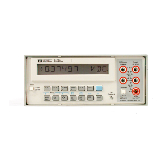
The 3478A is a full 6 digit multimeter capable of reading signals from 0.1µV to 300V
peak. The meter is quite flexible in resolution and scaling modes, but also has a lot of
advanced features for communications and programming that we will not cover here.
Display:
The display will indicate the number and range of the reading begin taken. It also has a
number of small indicators along the bottom of the screen to indicate particular modes.
Much of the displayed modes are self explanatory.
Control Buttons:
There are two rows of function buttons located under the display. These buttons control
what is being measured and how it is measured.
The first control to note is the "cal enable" switch to the right. This should NEVER be
turned to the cal position (vertical)
The second thing to note is that some buttons are dual function. Those with dual
functions are labeled by blue lettering above the button. Pressing the blue button places
the keyboard into "shift" mode, indicated by the word 'shift' on the display. IN this
mode the buttons perform the blue functions.
Advertisement
Table of Contents

Related Manuals for HP 3478A


Summary of Contents for HP 3478A
- Page 1 The 3478A is a full 6 digit multimeter capable of reading signals from 0.1µV to 300V peak. The meter is quite flexible in resolution and scaling modes, but also has a lot of advanced features for communications and programming that we will not cover here.
- Page 2 Function selections: The function selections are controlled from the upper row of buttons and are as follows (left to right) DC Volts AC volts 2 wire resistance 4 wire resistance DC amps AC amps Below this row is a second row of buttons. The first is the auto range switch. When the instrument is turned on initially it will be in auto range mode.
- Page 3 There are 5 connectors used for measurements. The middle connection on the right is the normal common connection for voltage and current readings. The upper connecton on the right is the normal positive connection for ac and dc readings. The lower connection on the right side is for current readings.
Need help?
Do you have a question about the 3478A and is the answer not in the manual?
Questions and answers