Table of Contents
Advertisement
Quick Links
Advertisement
Table of Contents

Related Manuals for Advantech POC-S196


Summary of Contents for Advantech POC-S196
- Page 1 User Manual POC-S196 19” Slim Point-of-Care Terminal...
- Page 2 Note! A NOTE provides additional information intended to avoid inconve- niences during operation. Part No. 2008019600 Edition 1 Printed in Taiwan May 2008 POC-S196 User Manual...
-
Page 3: Safety Instructions
Repair of the device may only be carried out by trained service personnel. It is rec- ommended that a service contract be obtained with Advantech and also that all repairs be carried out by them. Failure to do so may result in the incorrect functioning of the device. - Page 4 Maintenance: To properly maintain and clean the surfaces, use only the approved products or clean with a dry applicator. Caution! When servicing the device, always use replacement parts that meet Advantech standards. Advantech Medical cannot warrant or endorse the safe performance of third-party replacement parts for use with our medical device.
- Page 5 If interference is occur- ring, the user is encouraged to try to correct the interference by one or more of the following measures: Reorient or relocate the receiving antenna. POC-S196 User Manual...
- Page 6 Otherwise the correct functioning of the device may be compromised. Additional Information and Assistance Contact your distributor, sales representative, or Advantech's customer service cen- ter for technical support if you need additional assistance. Please have the following information ready before you call:...
- Page 7 Distributed in Europe by: Advantech Europe GmbH Kolberger Straße 7 D-40599 Düsseldorf, Germany Tel: 49-211-97477350 Fax: 49-211-97477300 Visit the Advantech websites at www.advantech.com or www.advantech.com.tw if you need more information. POC-S196 User Manual...
- Page 8 POC-S196 User Manual viii...
-
Page 9: Table Of Contents
Introduction ....................2 Specifications .................... 2 Table 1.1: Touchscreen Specification ......... 4 LCD Specifications..................5 Dimensions ....................5 Figure 1.1 Dimensions of the POC-S196 ........5 Chapter System Setup ........7 A Quick Tour of the POC-S196..............8 Figure 2.1 Front view of the Point-of-care terminal...... 8 Figure 2.2 Rear view of the Point-of-care terminal ...... - Page 10 Appendix A Description of Connectors....41 Description of Connectors............... 42 Figure A.1 POC-S196 motherboard top side view showing all local connectors..............42 Figure A.2 POC-S196 motherboard bottom side view showing all local connectors ............43 Table A.1: Description of Connector.......... 44...
-
Page 11: Chapter 1 General Information
Chapter General Information Sections include: ! Introduction ! Specifications ! LCD Specifications ! Dimensions... -
Page 12: Introduction
1000 Ethernet port, Single COM port, Quad USB 2.0 port and a 24-bit stereo audio controller. With a built-in 2.5” HDD drive, the POC-S196 is as slim and user-friendly as a notebook computer, and generates low audible noise. For system integrators, this silent, compact, mobile and highly integrated multimedia system lets you easily build a Point-of-Care Terminal into your applications. - Page 13 Altitude: Operational: 6,000 feet; Shipping: 40,000 feet Certifications: – EMC: CE, FCC approved – Safety: UL60601-1 and EN60601-1 approved This device bears the CE label in accordance with the provisions of the EMC Direc- tive 89/336/EMC and the Low Voltage Directive 73/23/EEC. POC-S196 User Manual...
-
Page 14: Table 1.1: Touchscreen Specification
During normal use, the POC-S196 may become soiled and should therefore, be cleaned regularly. Agents: Green tinctured soap and Enzymatic detergents Steps: Wipe the POC-S196 with a clean cloth that has been moistened in the cleaning solution. Prepare agent per manufacturer’s instructions or hospital protocol. -
Page 15: Lcd Specifications
Colors: 16.7 M (8 bits/color) Dot size (mm): 0.294 x 0.294 Viewing angle: 178° x 178° Luminance: 300 cd/m Contrast ratio: 1300 : 1 LCD MTBF: 50,000 hours Backlight lifetime: 50,000 hours Dimensions 471.5 110.9 Figure 1.1 Dimensions of the POC-S196 POC-S196 User Manual... - Page 16 POC-S196 User Manual...
-
Page 17: Chapter 2 System Setup
Chapter System Setup Sections include: ! A Quick Tour of the POC-S196 ! Installation Procedures ! Running the BIOS Setup Pro- gram ! Installing System Software ! Installing the Drivers... -
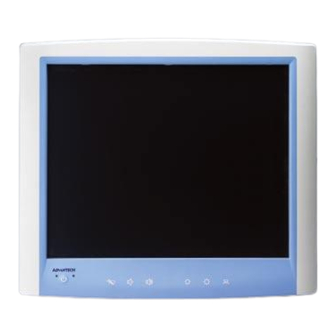
Page 18: A Quick Tour Of The Poc-S196
A Quick Tour of the POC-S196 Before you start to set up the POC-S196, take a moment to become familiar with the locations and purposes of the controls, drives, connections and ports, which are illus- trated in the figures below. -
Page 19: Figure 2.2 Rear View Of The Point-Of-Care Terminal
PC, as shown in Figure 2.2. (The I/O section includes various I/O ports, including serial ports, DVI port, Ethernet port, USB ports, DC power adapter jack, and so on.) Figure 2.2 Rear view of the Point-of-care terminal POC-S196 User Manual... -
Page 20: Installation Procedures
Installation Procedures 2.2.1 Connecting the Power Cord The POC-S196 can only be powered by a DC power adapter (SINPRO Model No MPU100-107). Always handle the power cords by holding the plug ends only. Follow these procedures in order: Connect the male end of the power adapter to the DC jack of the panel PC. (See Figure 2.3.) -
Page 21: Running The Bios Setup Program
Running the BIOS Setup Program The POC-S196 is likely to have been properly set up and configured by your dealer prior to delivery. It still may be necessary to use the BIOS (Basic Input-Output Sys- tem) setup program to change system configuration information, such as the current date and time or type of hard drive. -
Page 22: Installing The Drivers
Figure 2.4 The file directory on the "Drivers and Utilities" CD-ROM Note! The drivers and utilities used for the POC-S196 panel PCs are subject to change without notice. If in doubt, check Advantech's website or con- tact our application engineers for the latest information regarding drivers and utilities. -
Page 23: Chapter 3 Chipset And Graphics Setup
Chapter Chipset and Graphics Setup Sections include: ! Introduction ! Installation of Chipset Driver... -
Page 24: Introduction
3.1.1 Chipset The POC-S196 uses a Mobile Intel® 945GME Express chipset for its graphic control- ler. It supports an SDVO device, and CRT monitors. The Mobile Intel® 945GM Express Chipsets are designed for use with Intel’s next generation mobile platforms: Intel®... -
Page 25: Installation Of Chipset Driver
The CD-ROM drive is designated as “D” throughout this chapter. Note! <Enter> means pressing the “Enter” key on the keyboard. Note! Before installing the graphics driver of the POC-S196, please ensure you have installed the “Intel Chipset Software Installation Utility”. This can be found on the Utility CD-ROM. Note! Resolution of the window display is set at 640 x 480 before installation of the graphics driver. -
Page 26: Installation For Windows Xp
3.2.1 Installation for Windows XP Step1.1. Double Click “Setup.exe” in the D:\Driver\Chipset\ folder. The Install dialog will appear. Step 1.2. Click “Next” to continue. Step 1.3. Read the ‘License Agreement’ and click “Yes” to proceed. POC-S196 User Manual... - Page 27 Step 1.4. Read the ‘Readme’ file information and click “Next” to proceed. Step 1.5. When the ‘Installation is Complete’ message appears, click 'Finish' to restart your computer. POC-S196 User Manual...
- Page 28 Step 2.1. Double Click “Setup.exe” in the D:\Driver\GRAPHICS folder. The Install dialog will appear. Step 2.2. Click “Next” to continue. Step 2.3. Read the ‘License Agreement’ and click “Yes” to proceed. POC-S196 User Manual...
- Page 29 Read the ‘Readme’ file information and click “Next” to proceed. Step 2.5. When the ‘Click Next to continue’ message appears click “Next” to proceed. Step 2.6. When the ‘Setup Is Complete’ message appears click “Finish” to restart your computer. POC-S196 User Manual...
- Page 30 POC-S196 User Manual...
-
Page 31: Chapter 4 Audio Interface
Chapter Audio Interface Sections include: ! Introduction ! Installation of Audio Driver ! Further Information... -
Page 32: Introduction
Before installing the audio driver, please take note of the procedures detailed below. You must know which operating system you are using with your POC-S196, and then refer to the corresponding installation flow chart. Following the steps in the flow chart you can quickly and successfully complete the installation, even if you are not familiar with Windows installation instructions. -
Page 33: Installation For Windows 2000/Xp
Installation for Windows 2000/XP Step 1.1. Double Click “Setup.exe” in the D:\Driver\AUDIO folder. The Install dialog will appear. Step 1.2. Click “Next” to continue. The install program will install the driver and utilities. It will take some time to process. POC-S196 User Manual... -
Page 34: Further Information
When the ‘InstallShield Wizard Complete’ message appears click “Finish” to restart your computer. Further Information For further information about the audio interface installation on your POC-S196, including driver updates, troubleshooting guides and FAQ lists please visit the follow- ing web resources: Realtek website: www.realtek.com.tw... -
Page 35: Chapter 5 Pci Express Ethernet Interface
Chapter PCI Express Ethernet Interface Sections include: ! Introduction ! Installation of Ethernet Driver ! Further Information... -
Page 36: Introduction
Introduction The POC-S196 is equipped with a high performance PCIe Ethernet chipset, the Realtek RTL8111B which is fully compliant with IEEE 802.3 10/100/1000 Mbps stan- dards. The Ethernet port provides a standard RJ-45 jack. Installation of the Ethernet Driver 5.2.1 Installation for Windows XP Step 1.1. - Page 37 Step 1.3. Click “Install” to continue. The install program will install the driver. It will take some time to process. Step 1.4. When the ‘InstallShield Wizard Complete’ message appears click “Finish” to finish the install program. POC-S196 User Manual...
-
Page 38: Further Information
Further Information For further information about the installation on your POC-S196, including driver updates, troubleshooting guides and FAQ lists please visit the following web resources: Realtek website: www.realtek.com.tw Advantech websites: www.advantech.com www.advantech.com.tw POC-S196 User Manual... -
Page 39: Chapter 6 Touch Panel Interface
Chapter Touch Panel Interface Sections include: ! Introduction ! Installation of Touch Panel Driver ! Further Information... -
Page 40: Introduction
Introduction The POC-S196 is supported with a system-integrated touch panel. The touch panel controller is controlled by the COM3 interface. Installation of Touch Panel Driver 6.2.1 Installation for Windows XP Step 1.1. Double click “Setup.exe” in the D:\Driver\TOUCHSCREEN folder. The Install dialog will appear. - Page 41 Step 1.3. Click “Next” to continue. Since the POC-S196’s touch controller is controlled by COM3, please do not select the ‘Install PS/2 interface driver’. Step 1.4. Click “Next” to continue. Please select “None” for ‘Do 4 point calibration’, the driver install program will do this four point calibration when the install is complete.
- Page 42 Step 1.5. Click “Next” to continue. Please select “Support Multi-Monitor System”. Step 1.6. Click “Next” to continue. If you want to change the driver destination folder, you can click the “Browse” button to change the folder. POC-S196 User Manual...
- Page 43 Step 1.7. Click “Next” to continue. Step 1.8. Click “Yes” to continue. The install program will search the touchscreen controller to find it on COM3. POC-S196 User Manual...
-
Page 44: Further Information
Touch the “X” once at each of the four corners when it appears on the panel. Touch each “X” icon until the icon stops blinking. Further Information For further information about the installation on your POC-S196, including driver updates, troubleshooting guides and FAQ lists please visit the following web resources: Advantech websites: www.advantech.com... -
Page 45: Utilities And Hot Fixes
Chapter Utilities and Hot Fixes Sections include: ! Introduction ! Wakeup by External USB Device at S3 Resume (Wakeup) ! Window Audio Volume Applica- tion... -
Page 46: Introduction
Click “OK” to close the window following successful installation. Window Audio Volume Application On the front panel of the POC-S196 system, there are two buttons to control the speaker volume. This speaker volume is adjustable by pressing the button and it does not require any special software utility. -
Page 47: Operation Information
Chapter Operation Information Sections include: ! Plug in the Power Adapter ! Thermal Information ! Disconnect the Power ! General Safety Guide... -
Page 48: Plug In The Power Adapter
Thermal Information When using the POC-S196 system, it is normal for the rear metal heatsink to get warm. The rear metal heatsink of the POC-S196 case functions as a cooling surface that transfers heat from inside the computer to the cooler air outside. Do not block this heatsink with any soft material. -
Page 49: General Safety Guide
The power cord or plug becomes frayed or otherwise damaged You spill something into the case Your computer has been dropped or the case has been otherwise damaged You suspect that your computer needs service or repair You want to clean the case POC-S196 User Manual... - Page 50 POC-S196 User Manual...
-
Page 51: Appendix A Description Of Connectors
Appendix Description of Connectors... -
Page 52: Description Of Connectors
Description of Connectors Figure A.1 POC-S196 motherboard top side view showing all local connectors POC-S196 User Manual... -
Page 53: Connectors
Figure A.2 POC-S196 motherboard bottom side view showing all local connectors POC-S196 User Manual... -
Page 54: Table A.1: Description Of Connector
PATA Connector USB Header USB Card Reader COM4 Header SATA Power Connector 0 GPIO Header SATA Connector Channel 0 COM Port Pin 9 configuration SATA Connector Channel 2 COM1 RS232/422/485 Selection Jumper (Default: RS232) Clear CMOS button POC-S196 User Manual... -
Page 55: Appendix B Windows Display Hot Key Function
Appendix Windows Display Hot Key Function... -
Page 56: Windows Display Hot Key Function
Hot Key Display Device Ctrl+Alt+F1 External CRT Monitor Ctrl+Alt+F3 Internal LCD Panel Ctrl+Alt+F4 External DVI Monitor The display content will be switched to the dedicated display device indicated. POC-S196 User Manual... - Page 57 POC-S196 User Manual...
- Page 58 No part of this publication may be reproduced in any form or by any means, electronic, photocopying, recording or otherwise, without prior written permis- sion of the publisher. All brand and product names are trademarks or registered trademarks of their respective companies. © Advantech Co., Ltd. 2008...
Need help?
Do you have a question about the POC-S196 and is the answer not in the manual?
Questions and answers