Table of Contents
Advertisement
Quick Links
Advertisement
Table of Contents

Related Manuals for Advantech POC-155


Summary of Contents for Advantech POC-155
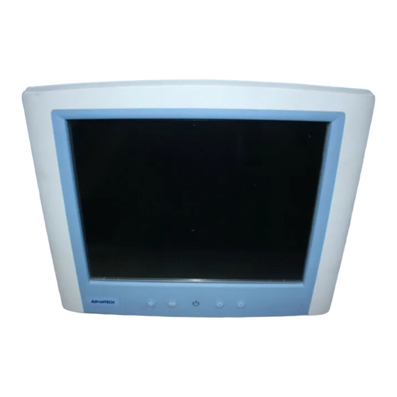
- Page 1 POC-155 Point-of-Care Terminal with 15" TFT LCD User Manual...
- Page 2 SMI is a trademark of Silicon Motion, Inc. Creative is a trademark of Creative Technology LTD. All other product names or trademarks are properties of their respective owners. This manual is for the POC-175. Part No. 2006015500 1st Edition, Printed in Taiwan Sep 2006 POC-155 User Manual...
- Page 3 FCC Class B This equipment has been tested and found to comply with the limits for a Class B digital device, pursuant to Part 15 of the FCC Rules. These limits are designed to provide reasonable protection against harm- ful interference when the equipment is operated in a residential environ- ment.
- Page 4 Packing List Before installing your Point of Care Terminal, ensure that the following materials have been received: • POC-155 series Point of Care Terminal • User manual • Accessories for POC-155 – Y-shaped adapter for PS/2 mouse and keyboard – Power cord (1.8 m) - USA type (UK, German types are available on request) –...
- Page 5 2. Use a 3 V @ 195 mA lithium battery (Model No. BR2032) 3. Packing: please carry the unit with both hands, handle with care 4. Our European representative: Advantech Europe GmbH Kolberger Straße 7 D-40599 Düsseldorf, Germany Tel: 49-211-97477350 Fax: 49-211-97477300 5.
- Page 6 ENVIRONMENT WHERE THE STORAGE TEMPERATURE IS BELOW -20° C (-4° F) OR ABOVE 60° C (140° F). THIS MAY DAMAGE THE EQUIPMENT. If your computer is losing time or the BIOS configuration resets to defaults, the battery has no power. POC-155 User Manual...
- Page 7 Caution 1. Do not replace the battery yourself. Please contact a qualified technician or your retailer. 2.The computer is provided with a battery-powered real-time clock circuit. There is a danger of explosion if the battery is incorrectly replaced. Replace only with same or equivalent type recommended by the manufacturer.
- Page 8 The sound pressure level at the operator's position according to IEC 704-1:1982 is no more than 70dB (A). DISCLAIMER This set of instructions is given according to IEC 704-1. Advantech disclaims all responsibil- ity for the accuracy of any statements contained herein POC-155 User Manual...
-
Page 9: Table Of Contents
Cleaning/Disinfecting............5 LCD Specifications ............6 Dimensions................ 7 Chapter 2 System Setup..........10 A Quick Tour of the POC-155 ........10 Installation Procedures ............ 13 2.2.1 Connecting the power cord ......... 13 2.2.2 Connecting the keyboard and mouse ......14 2.2.3... - Page 10 Disassembling the Panel PC..........71 Installing the 2.5" Hard Disk Drive (HDD) ....72 Installing the Central Processing Unit (CPU) ....73 Appendix D Programing the Watchdog Timer....76 Appendix E VESA Mounting ..........80 Install VESA Mounting........... 80 POC-155 User Manual...
- Page 11 General Information This chapter gives an overview of the POC-155. Sections include: • Introduction • Specifications • Cleaning/Disinfecting • LCD Specifications • Dimensions...
-
Page 12: Chapter 1 General Information
Ethernet controller, multiple COM port interfaces and 18-bit stereo audio controller. With a built-in CD-ROM drive and mini PCI expansion slot, the POC-155 is as compact and user-friendly as a notebook computer. This simple, complete and highly integrated multimedia system lets sys- tem integrators easily build a Point of Care Terminal into their applica- tions. -
Page 13: Flat Panel Interface
• CPU: Socket 479 Intel® Pentium® Mobile up to 2.0 GHz • BIOS: Award 512 KB Flash BIOS, supports Plug & Play, APM • Chipset: Intel® 915GM GMCH, 82801FBM (ICH6-M) • Front side Bus: FSB 533/400 MHz • RAM: 240 pins DDR2 DIMM slots x 2, supports unbuffered 400/533 MHz DDR2 SDRAM (Non ECC), capacity maximum to 2 GB •... -
Page 14: Ethernet Interface
1.2.7 Touchscreen (optional) Type Analog Resistive Resolution Continuous Light Transmission Controller RS-232 interface (uses COM4) Power Consumption +5 V @ 200 mA Software Driver Supports Windows 2000,Windows XP Durability (touches in a lifetime) 30 million Table 1.1:Touchscreen specification POC-155 User Manual... -
Page 15: Environment
– This device bears the CE label in accordance with the provisions of the EMC Directive 89/336/EMC. 1.3 Cleaning/Disinfecting During normal use of the POC-155 may become soiled and should, there- fore, be cleaned regularly. Agents: Green tinctured soap and Enzymatic detergents. -
Page 16: Lcd Specifications
Cautions Do not immerse or rinse the POC-155 and its periph- erals. If you accidentally spill liquid on the device, dis- connect the unit from the power source. Contact your Biomed regarding the continued safety of the unit before placing it back in operation. -
Page 17: Dimensions
1.5 Dimensions Figure 1.1: Dimensions of the POC-155 Chapter 1... - Page 18 POC-155 User Manual...
- Page 19 System Setup This chapter gives hardware and sys- tem software installation information. Sections include: • A Quick Tour of the POC-155 • Installation Procedures • Running the BIOS Setup Program • Installing System Software • Installing the Drivers...
-
Page 20: Chapter 2 System Setup
Chapter 2 System Setup 2.1 A Quick Tour of the POC-155 Before you start to set up the POC-155, take a moment to become famil- iar with the locations and purposes of the controls, drives, connections and ports, which are illustrated in the figures below. - Page 21 When you look at the left side of the panel PC, you will see the CD-ROM drive, two USB 2.0 ports and two IEEE1394a ports, as shown in Figure 2- IEEE 1394a IEEE 1394a USB 2.0 USB 2.0 Figure 2.2: Left side view of the Point of Care Terminal When you turn the Point of Care Terminal around and look at its rear cover, you will find the PCI expansion slot located on the left side.
- Page 22 USB ports, the microphone jack, and so on). Figure 2.3: Functional Earth Ground Connector Isolated RS-232 COM port (COM1 /COM2/COM3) PS/2 Mouse/Keyboard Port IEEE-1394a Port Parallel Port Line-out/Line-in/MIC-in Port (From left to right) D-sub VGA port USB 2.0 Ports RJ-45 Gigabit LAN Port POC-155 User Manual...
-
Page 23: Installation Procedures
2.2 Installation Procedures 2.2.1 Connecting the power cord Be sure to always handle the power cords by holding the plug ends only. Connect the female end of the power cord to the AC inlet of the panel PC. (See Figure 2-5.) Connect the 3-pin male plug of the power cord to an electrical out- let. -
Page 24: Connecting The Keyboard And Mouse
2.2.2 Connecting the keyboard and mouse Connect the Y-shaped adapter to the PS/2 mouse and keyboard port on the I/O section of the POC-155. (See Figure 2-6.) Connect the PS/2 mouse and keyboard to the Y-shaped adapter. If you use a serial mouse, you can connect the mouse to any COM port in the I/O section. -
Page 25: Running The Bios Setup Program
2.3 Running the BIOS Setup Program Your POC-155 is likely to have been properly set up and configured by your dealer prior to delivery. You may still find it necessary to use the BIOS (Basic Input-Output System) setup program to change system con- figuration information, such as the current date and time or your type of hard drive. -
Page 26: Installing The Drivers
The standard procedures for installing the SVGA, audio, touchscreen, and Ethernet drivers are described in Chapters 3, 4, 5, and 6 respectively. The utility directory includes multimedia programs. Refer to the README.TXT file inside the VGA folders for more detailed informa- tion. POC-155 User Manual... - Page 27 CD-ROM is: Figure 2.7: The file directory on “Drivers and Utilities” CD-ROM Note The drivers and utilities used for the POC-155 panel PCs are subject to change without notice. If in doubt, check Advantech's website or contact our application engineers for the latest information regarding drivers and utilities.
- Page 28 POC-155 User Manual...
- Page 29 Graphic Chipset Setup This chapter gives details of graphics chipset setup. Sections include: • Introduction • Installation of Graphic Driver • Further information...
-
Page 30: Chapter 3 Graphic Chipset Setup
Chapter 3 Graphic Chipset Setup 3.1 Introduction The POC-155 has an onboard VGA interface. The specifications and fea- tures are described as follows: 3.1.1 Chipset The POC-155 uses Mobile Intel® 915GM Express chipset for its graphic controller. It supports SDVO device, and CRT monitors. The Mobile Intel®... -
Page 31: Installation Of Graphic Driver
Note2 <Enter> means pressing the “Enter” key on the key- board. Note3 Before you install the graphic driver of POC-155, please ensure you have installed the “Intel Chipset Software Installation Utility”. You can find this driver in the Utility CD-ROM. -
Page 32: Installation For Windows Xp
3.2.1 Installation for Windows XP Click the 'Start' button in the task bar, click 'Run' and then select 'infinst_autol.exe' from the drive directory “D:/Chipsetsoftware/” where the driver files are stored. The Install dialog will appear. Click 'Next' to continue. POC-155 User Manual... - Page 33 Read the License Agreement and click ‘Yes’ to proceed. Chapter 3...
- Page 34 When the 'Setup COMPLETE' message appears click 'Finish' to restart your computer. POC-155 User Manual...
- Page 35 Click the 'Start' button in the task bar, click 'Run' and then select ‘Setup.exe’ from the drive directory “D:/VGA/” where the driver files are stored. The Install dialog will appear. Click 'Next' to continue. Chapter 3...
- Page 36 Read the License Agreement and click ‘Yes’ to proceed. POC-155 User Manual...
- Page 37 When the 'Setup COMPLETE' message appears click 'Finish' to restart your computer. Chapter 3...
-
Page 38: Further Information
3.3 Further information For further information about the VGA installation in your POC-155, included driver updates, troubleshooting guides and FAQ lists please visit the following web resources. Intel website: www.intel.com.tw Advantech websites: www.advantech.com www.advantech.com.tw POC-155 User Manual... - Page 39 Audio Interface This chapter gives details of audio interface setup. Sections include: • Introduction • Installation of Audio Driver • Further information...
-
Page 40: Chapter 4 Audio Interface
Before installing the audio driver, please take note of the procedures detailed below. You must know which operating system you are using in your POC-155, and then refer to the corresponding installation flow chart. Just follow the steps in the flow chart. You can quickly and suc- cessfully complete the installation, even though you are not familiar with instructions for Windows. -
Page 41: Installation For Windows 2000/Xp
4.2.1 Installation for Windows 2000/XP Click the 'Start' button in the task bar, click 'Run' and then select 'infinst_autol.exe' from the drive directory “D:/Audio/” where the driver files are stored. The Install dialog will appear. Click 'Next' to continue. Chapter 4... -
Page 42: Further Information
When the 'Setup COMPLETE' message appears click 'Finish' to restart your computer. 4.3 Further information For further information about the audio interface installation in your POC-155, included driver updates, troubleshooting guides and FAQ lists please visit the following web resources. Realtek website: www.realtek.com.tw Advantech websites: www.advantech.com... - Page 43 Touchscreen Interface This chapter gives details of touch- screen interface setup. Sections include: • Introduction • Installation of Touchscreen Drivers • Further information...
-
Page 44: Chapter 5 Touchscreen Interface
Chapter 5 Touchscreen Interface 5.1 Introduction 5.1.1 General Information The POC-155's optional touchscreen incorporates advanced second-gen- eration 5-wire resistive technology. They allow 75% light transmission. The resistive and capacitive models have an antiglare surface. All models provide greatly enhanced visual resolution. They also have new improved scratch-resistant features. -
Page 45: Installation Of Touchscreen Drivers
– Mineral spirits – Foods and beverages 5.2 Installation of Touchscreen Drivers To facilitate installation of the touchscreen driver, you should read the instructions in this section carefully before you attempt installation. Impor- The following windows illustrations are examples tant only. - Page 46 Click 'Ok' to continue. Click 'Unzip' to continue. POC-155 User Manual...
- Page 47 Click 'Ok' to continue. Click 'Next' to continue. Chapter 5...
- Page 48 Read the License Agreement and click ‘Yes’ to proceed. Click 'Next' to continue. POC-155 User Manual...
- Page 49 Click 'Next' to continue. Chapter 5...
- Page 50 Click 'Next' to continue. POC-155 User Manual...
- Page 51 When the 'Setup COMPLETE' message appears click 'Finish'. And follow upthe on-screen instructions to complete touchscreen calibration procedures. Chapter 5...
-
Page 52: Further Information
5.3 Further information For further information about the Touchscreen installation in your POC- 155, included driver updates, troubleshooting guides and FAQ lists please visit the following web resources. Elo website: www.elotouch.com Advantech websites: www.advantech.com www.advantech.com.tw POC-155 User Manual... - Page 53 PCI Express Ethernet Interface This chapter gives details of Ethernet interface setup. Sections include: • Introduction • Installation of Ethernet Driver • Further information...
-
Page 54: Chapter 6 Pci Express Ethernet Interface
Chapter 6 PCI Express Ethernet Inter- face 6.1 Introduction The POC-155 is equipped with a high performance Marvell 88E805 PCIe Ethernet chipset 3 which is fully compliant with IEEE 802.3 10/100/1000 Mbps standards. The Ethernet port provides a standard RJ-45 jack. - Page 55 Click 'Next' to continue. When the 'Setup COMPLETE' message appears click 'Finish' to restart your computer. Chapter 6...
-
Page 56: Further Information
6.3 Further information For further information about the Ethernet installation in your POC-155, included driver updates, troubleshooting guides and FAQ lists please visit the following web resources. Marvell website: www.marvell.com Advantech websites: www.advantech.com www.advantech.com.tw POC-155 User Manual... - Page 57 Connector Pinouts This appendix gives details of connec- tor pinouts. Sections include: • ATX Power Connector • Inverter Power Connector • Internal Speaker Connector • Front Panel Control Connector (*Reserved) • IR Connector (*Reserved) • EIDE Hard Disk Drive Connector- (Secondary Master) •...
-
Page 58: Appendix A Connector Pinouts
Appendix A Connector Pinouts A.1 ATX Power Connector Figure A.1: POC-155 ATX power connector Table A.1: ATX power connector (CN37) Pin No. Signal Description 3.3V 3.3V 5 VSB 12 V 3.3V -12V PSON POC-155 User Manual... -
Page 59: Inverter Power Connector
A.2 Inverter Power Connector Figure A.2: POC-155 Inverter power connector Table A.2: Inverter power connector (CN3 Pin No. Signal Description +12 V ENABLE Brightness Adjustment Appendix A... -
Page 60: Internal Speaker Connector
A.3 Internal Speaker Connector Figure A.3: Table A.3: POC-155 Internal speaker connector(CN26) Pin No. Signal Description Speaker out_R- Speaker out_R+ Speaker out_L+ Speaker out_L- A.4 Front Panel Control Connector (*Reserved) Figure A.4: POC-155 Flat panel control connector POC-155 User Manual... -
Page 61: Ir Connector (*Reserved)
Pin No. Signal Description Power SW+ Power SW- Table A.5: Reset connector (J3) Pin No. Signal Description RESET SW A.5 IR Connector (*Reserved) Figure A.5: POC-155 IR connector Table A.6: IR connector (CN12) Pin No. Signal Description IR_IN IR_OUT Appendix A... -
Page 62: Eide Hard Disk Drive Connector (Primary/Master)
A.6 EIDE Hard Disk Drive Connector (Primary/Master) Figure A.6: POC-155 EIDE hard drive connector Table A.7: EIDE hard disk connector (CN10) Pin No. Signal Description IDE RESET# DATA7 DATA8 DATA6 DATA9 DATA5 DATA10 DATA4 DATA11 DATA3 DATA12 DATA2 POC-155 User Manual... - Page 63 DATA13 DATA1 DATA14 DATA0 DATA15 SIGNAL GND HDD DREQ IO WRITE IO READ HD READY CABLE SELECT HD ACK0# IRQ14 ADDR1 ADDR0 ADDR2 HDD SELECT 0# HDD SELECT 1# IDE ACTIVE 0# # Low active Appendix A...
-
Page 64: Cd-Rom Connector (Primary/Slave)
Pin No. Signal Description Audio_L Audio_R IDE RESET # DATA8 DATA7 DATA9 DATA6 DATA10 DATA5 DATA11 DATA4 DATA12 DATA3 DATA13 DATA2 DATA14 DATA1 DATA15 DATA0 HDD DREQ IO READ IO WRITE HD READY HD ACK0# IRQ15 ADDR1 ADDR0 POC-155 User Manual... -
Page 65: Cpu Fan Power Connector
ADDR2 HDD SELECT 0# HDD SELECT 1# Vcc (+5V) Vcc (+5V) A.8 CPU Fan Power Connector Figure A.7: POC-155 CPU fan connector Table A.9: CPU fan power connector (CN19) Pin No. Signal Description FAN_DET +12V Appendix A... -
Page 66: System Fan Power Connector
A.9 System Fan Power Connector Figure A.8: POC-155 System fan connector Table A.10: System fan power connector (CN39) Pin No. Signal Description FAN_DET +12V A.10 PCI Bus Expansion Connector (PCI1) Figure A.9: POC-155 PCI slot connector Note This PCI slot uses standard PCI Bus V2.2. If you wish to use this slot, you can connect the add-on cards directly without any issues. -
Page 67: Cpu Selection Switches
A.11 CPU Selection Switches Table A.11: CPU Selection Switch SW1 Pin No. Dothan Banias 533 Banias 400 (Default) Table A.12: CPU Selection Switch SW2 Pin No. Dothan Banias 533 Banias 400 (Default) Appendix A... -
Page 68: Com2
A.12 COM2 Figure A.10: POC-155 COM2 connector Table A.13: COM2 pin assignment Configure Signal Description Pin No. RS-232 RS-422 RS-485 DATA- DATA+ POC-155 User Manual... -
Page 69: Locating Connectors
R858 C703 R857 C704 C734 R929 R875 R542 R541 C757 R885 C758 R889 C571 C759 R891 CN16 CN14 R964 C481 CN33 CN15 CN20 CN31 CN27 CN28 CN29 CN41 Internal speaker Figure A.11: Locating connectors on the POC-155 motherboard Appendix A... - Page 70 POC-155 User Manual...
- Page 71 Jumper Setting and Connectors This appendix describes jumper set- tings. Sections include: • Jumpers and connectors • CPU Configuration • COM port Interface • Watchdog Timer Configuration...
-
Page 72: Appendix B Jumper Setting And Connectors
B.1.2 Jumpers and switches The motherboard of the Point of Care Terminal has a number of jumpers that allow you to configure your system to suit your applications. The table below lists the function of each of the board’s jumpers. POC-155 User Manual... -
Page 73: Locating Jumpers
CN26 R860 R858 C703 R857 C704 C734 R929 R875 R542 R541 C757 R885 C758 R889 C571 C759 R891 CN16 C481 CN14 R964 CN31 CN33 CN15 CN20 CN27 CN28 CN29 CN41 Figure B.2: Locating jumpers on the POC-155 motherboard Appendix B... -
Page 74: Cpu Configuration
Mobile or Celeron™ Mobile CPU. See Appendix C for detailed information. B.3 COM port Interface The Point of Care Terminal provides three serial ports (COM1/COM3: RS-232; COM2: RS-232/422/485 optional in one COM port connector). Figure B.3: COM port jumper POC-155 User Manual... -
Page 75: Com2 Output Type Setting (Jp9)
B.3.1 COM2 Output Type Setting (JP9) COM2 can be configured to operate in RS-232, RS-422, or RS-485 mode. This is done via JP9. JP9 is the 18 pins jumper close to the COM Port Connector. Figure B.4: COM2 port configuration Table B.2: COM2 Port Configuration (JP9) Pin No. - Page 76 Their selectable function is the same as the COM1/COM2 set. Table B.3: Serial port default settings Port No. IO Address Range Interrupt Request COM1 3F8 ~ 3FF IRQ4 COM2 2F8 ~ 2FF IRQ3 COM3 3E8 ~ 3EF IRQ10 POC-155 User Manual...
-
Page 77: Com1/Com2/Com3 Pin9 Output Type Setting (Jp4/ Jp6/Jp5)
B.3.2 COM1/COM2/COM3 Pin9 Output Type Setting (JP4/ JP6/JP5) Figure B.5: COM port Pin9 configuration Table B.4: COM Port Pin9 Output Type Configuration (JP5/JP6/JP7/JP8) Pin No. Open/Closed Function Description Pin3,4 Closed COM1/COM2/COM3 port Pin9 Ring (Default) Pin1,3 Closed COM1/COM2/COM3 port Pin9 output +5V * This function is for JP8 only. -
Page 78: Watchdog Timer Configuration
B.4 Watchdog Timer Configuration An onboard watchdog timer reduces the chance of disruptions which EMP (electromagnetic pulse) interference can cause. This is an invalu- able protective device for standalone or unmanned applications. (Refer to Appendix D.) POC-155 User Manual... - Page 79 Hardware Installation This appendix describes hardware installation. Sections include: • Overview of Hardware Installation and Upgrading • Disassembling the Panel PC • Installing the 2.5" Hard Disk Drive (HDD) • Installing the Central Processing Unit (CPU)
-
Page 80: Appendix C Hardware Installation
Terminal is high quality and reliable. However, it may contain few defective pixels which do not always illu- minate. With current technology, it is impossible to completely eliminate defective pixels. Advantech is actively working to improve this technology. Warning Do not remove the plastic rear cover until you have verified that no power is flowing within the panel PC. -
Page 81: Disassembling The Panel Pc
Care Terminal before you upgrade your system. All procedures are illus- trated in Figure C-1. Unscrew the screws that secure the plastic rear cover, and then remove the cover. Unscrew the screws that secure the metal fan cover. Figure C.1: Disassembling the plastic rear cover of the POC-155 Appendix C... -
Page 82: Installing The 2.5" Hard Disk Drive (Hdd)
(#1) from both sides of the HDD bracket. The HDD cable (1 x 44-pin to 1 x 44-pin) is next to the HDD bracket. Connect the HDD cable to the POC-155. Make sure that the red wire corresponds to Pin 1 on the connector (CN6), which is labeled on the board. -
Page 83: Installing The Central Processing Unit (Cpu)
C.4 Installing the Central Processing Unit (CPU) The Point of Care Terminal's central processing unit (CPU) can be upgraded to improve system performance. The Point of Care Terminal provides one 479-pin socket (Socket 479). The CPU must come with an attached heat sink and CPU fan to prevent overheating. - Page 84 Place the heat sink on top of the CPU and fasten it with the heat sink clip. Connect the CPU fan power cable to the 3-pin connector (FAN1). Put back the metal fan cover, and secure it with four screws. POC-155 User Manual...
- Page 85 Programing the Watch- dog Timer This appendix describes programming the watchdog timer.
-
Page 86: Appendix D Programing The Watchdog Timer
After data entry, your program must refresh the watchdog timer by rewriting the I/O port 443 (hex) while simultaneously setting it. When you want to disable the watchdog timer, your program should read I/O port 443 (hex). POC-155 User Manual... - Page 87 The following example shows how you might program the watchdog timer in BASIC: Figure D.1: Watchdog programming example in the BASIC Language Appendix D...
- Page 88 POC-155 User Manual...
- Page 89 VESA Mounting This appendix describes VESA mount- ing.
-
Page 90: Appendix E Vesa Mounting
The wall-mounting attachment is comprised of two parts: one back bracket, and one mounting bracket. Attach the back bracket to the rear cover of the POC-155, securing it in place with four of the Phillips-head screws provided. Attach the mounting bracket to a wall or other flat surface. The back bracket slides vertically from the top into the mounting bracket. - Page 91 Figure E.1: VESA mounting dimension diagram (75 x 75 mm, 100 x 100 mm ) Appendix E...
- Page 92 POC-155 User Manual...
Need help?
Do you have a question about the POC-155 and is the answer not in the manual?
Questions and answers