
Related Manuals for Honeywell SDC heating and district heating controller


Summary of Contents for Honeywell SDC heating and district heating controller
- Page 1 Smile SDC heating and district heating controller SERVICE MANUAL EN2H-0221GE51 R0808...
- Page 2 EN2H-0221GE51 R0808...
-
Page 3: Table Of Contents
SDC / DHC Contents Contents Software version ......................11 Safety instructions.......................11 Intended use .....................11 Requirements for start-up..................11 2.2.1 Power supply ..................12 2.2.2 Connection conditions ................12 2.2.3 Cable cross-sections ................12 2.2.4 Maximum cable lengths ................12 2.2.5 Cable installation ..................12 2.2.6 Grounding and zeroing .................13 Hot-water temperature greater than 60 °C ............13 Connection of accessory parts ................14 Maintenance and cleaning ................14... - Page 4 Contents SDC / DHC 5.1.2.9 Access to the technician / OEM area ........46 5.1.2.10 Heating curve ................47 Menu-selection level..................48 5.2.1 "Time - Date" menu ................54 5.2.2 "Timeprograms" menu ................55 5.2.2.1 Selection of the control circuit ..........56 5.2.2.2 Selection of the program ............56 5.2.2.3 Selection of day of the week and cycle ........56 5.2.2.4 Programming switching times and cycle temperatures ...57 5.2.3...
- Page 5 SDC / DHC Contents 5.4.7 "District hot water" menu (DIST.HEATING) ........104 5.4.8 "Return increase" menu (RETURN CONTR)........105 5.4.9 "Solar" menu (SOLAR) ...............106 5.4.10 "Solid" menu (SOLID FUEL)...............107 5.4.11 "Buffer" menu (BUFFER)..............108 5.4.12 "Total flow regulation" menu (MAIN SUPPLY)........109 5.4.13 "Cascading" menu (CASCADE) ............110 5.4.14 "Data bus"...
- Page 6 Contents SDC / DHC 6.8.8 System frost protection ...............124 6.8.9 Pump forced operation ...............127 Hydraulic Components....................128 Heat generator: Boiler ..................128 7.1.1 Heat generator start-up protection............128 7.1.2 Heat generator minimum temperature limit.........129 7.1.3 Maximum temperature limit heat generator ........130 7.1.4 Heating circuits minimum temperature limit ........130 7.1.5 Heat generator sensor control mode ..........130 7.1.6...
- Page 7 SDC / DHC Contents 7.2.7 Quick hot-water control...............152 7.2.8 Mode of operation of hot-water control mode "external operation" ...................154 7.2.9 Conditional parallel operation for mixed heating circuits.....155 7.2.10 Circulation pump control mode ............155 7.2.11 Switch-off of district heating control ............156 7.2.12 Return interval flushing ...............156 7.2.13 Heat meter for additional limitation according to the volume flow or thermal output ................156...
- Page 8 Contents SDC / DHC 7.3.4.3 Heating circuit room controller ..........171 7.3.4.4 Switch-on/switch-off optimisation ..........171 7.3.4.5 Room setpoint ramp..............175 7.3.4.6 Heating limit function.............175 7.3.4.7 Heating circuit room frost protection limit ......177 7.3.4.8 Mixed heating circuits cooling switch-over ......177 7.3.4.9 Heating circuit name .............180 7.3.4.10 Room thermostat function (maximum room temperature limit) ..............181 7.3.5...
- Page 9 SDC / DHC Contents 7.3.12.1 General description of cascading of control devices .....232 7.3.12.2 Function of the cascade parameters ........233 7.3.12.3 Mode of operation of cascade control ........234 7.3.13 Commissioning, maintenance and troubleshooting help ....237 7.3.13.1 Automatic set function............237 7.3.13.2 Emission measurement (not for DHC 43) ......238 7.3.13.3 Relay/function test..............239 Error messages....................243 7.4.1...
- Page 10 Contents SDC / DHC EN2H-0221GE51 R0808...
-
Page 11: Software Version
SDC / DHC Software version 1 Software version This documentation is valid for software version V 3.0 of your control device. The software version is displayed after switch-on for approx. 8 s. If you are using an older software version, please contact your heating technician. -
Page 12: Power Supply
Safety instructions SDC / DHC 2.2.1 Power supply Do not disconnect the controller from the mains supply! The battery for saving all individualised data is otherwise unnecessarily strained. The frost-protection function of the controller is deactivated. 2.2.2 Connection conditions All electrical connection work may only be carried out by qualified personnel! 2.2.3 Cable cross-sections... -
Page 13: Grounding And Zeroing
SDC / DHC Safety instructions 2.2.6 Grounding and zeroing Local regulations on the connection of equipment must be observed! Hot-water temperature greater than 60 °C ATTENTION Note that there is a danger of scalding at all hot-water draw- off points (kitchen, bathroom etc.) in the following cases. Add sufficient cold water in these cases. -
Page 14: Connection Of Accessory Parts
Safety instructions SDC / DHC Connection of accessory parts WARNING According to VDE 0730, a separator for each mains terminal is to be provided in the voltage supply to the control equipment. Observe the local regulations regarding grounding and zeroing. As soon as the mains voltage is applied to terminals 21, 22, 2, 6, 12 and 18, headers X3 and X4 can also carry mains voltage. -
Page 15: Safety Precautions For Emc-Compliant Installation
SDC / DHC Safety instructions Safety precautions for EMC-compliant installation Mains lines and sensor/data bus lines must be installed separate from each other. A minimum of 2 cm space must be present between the lines. It is permissible to cross lines. ç... - Page 16 Safety instructions SDC / DHC When installing control or wall devices, a minimum spacing of 40 cm to other electrical equipment with electromagnetic emissions, e.g. relays, motors, transformers, dimmers, microwave ovens and televisions, audio speakers, computers, cordless telephones etc., is to be ensured. ç...
- Page 17 SDC / DHC Safety instructions The mains connection of the heating system (boiler – panel – control equipment) must be designed as a separate circuit. Neither fluorescent lamps nor any machines which are potential sources of interference may be connected/connectable. ç...
- Page 18 Safety instructions SDC / DHC The earth connection of the cable shielding must occur on one side at the protective conductor connection, e.g. at the cladding plate of the heat generator, protective conductor terminal etc. Multiple earth connections of a single cable are not permissible (buzzing loop).
- Page 19 SDC / DHC Safety instructions With star-topology data bus systems, double earth connections may not be made. The earth connection must be made on one side of the star! Shielding Two-lead data bus line Distributor terminal Branch box The outside sensor may not be installed near transmitters or receivers (e.g.
-
Page 20: Overview
Overview SDC / DHC 3 Overview The modular SDC / DHC control device is available in an installable switch cabinet version and a surface-mounted wall version with the following equipment features: Type – – – – SDC 3-10 – – –... -
Page 21: Abbreviations
SDC / DHC Abbreviations 4 Abbreviations The following abbreviations are used in this documentation/in the display of the control device: Lowering operation BS 2 Buffer sensor 2 (bottom) Outside sensor Buffer loading pump Outside sensor 2 Return bypass pump Flue gas sensor Return pump Outside temperature SD I... -
Page 22: Operation
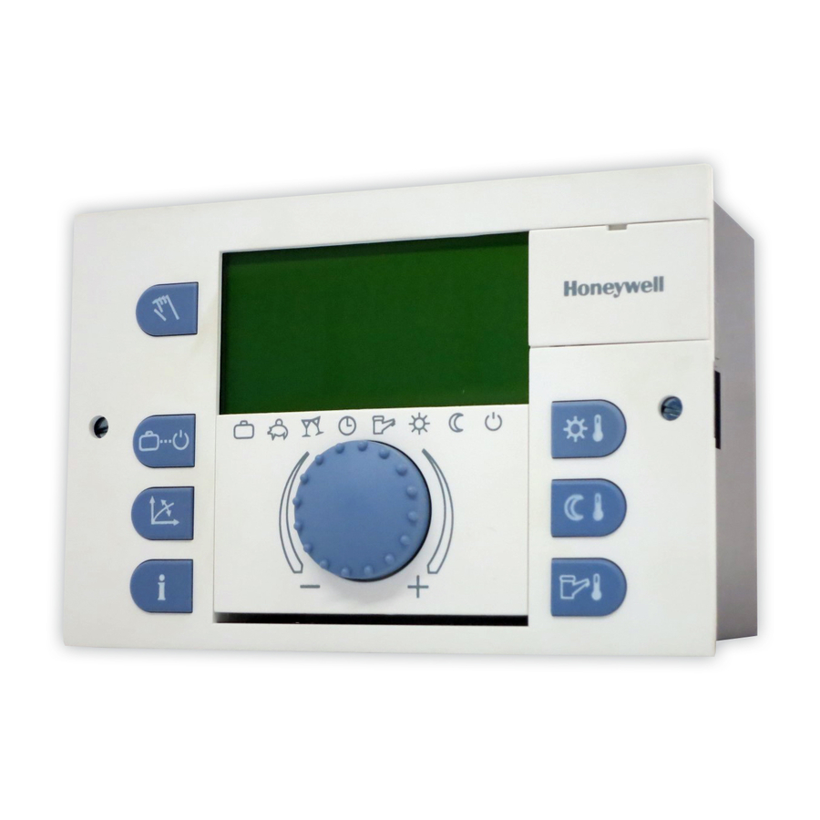
Operation SDC / DHC 5 Operation Display and operating elements 1 "Manual mode" / "Emission measurement" button (not on district heating controllers) 2 "Operating modes" button (basic display) 3 "Switching time programs" / "Holiday programs" button 4 "System information" button 5 Display 6 Cover clip for service socket 7 "Daytime room temperature"... -
Page 23: Display (Basic Display)
SDC / DHC Operation 5.1.1 Display (basic display) Day of the week / Date Operating mode symbols Time Heat generator temperature Active operating mode The illumination of the display is switched on by pressing any button or using the input button î... -
Page 24: Operating Elements
Operation SDC / DHC 5.1.2 Operating elements 5.1.2.1 Input button (press / turn) By pressing once, you can: ð • Confirm input / values By pressing and holding (approx. 3 s), you can: • Switch to the menu-selection level • Move up one menu level By turning the input button î... -
Page 25: Night-Time Room Temperature" Button
SDC / DHC Operation 5.1.2.3 "Night-time room temperature" button Sets the lowered room temperature in automatic mode between ¦ the heating cycles and in the ABSENT and RED. HEATING operating modes. In operating mode 1, the set value for all heating circuits is the same. -
Page 26: Operating Mode" Button (Basic Display)
Operation SDC / DHC Setting range 5 °C (hot-water economy temperature) ... Maximum hot-water heater temperature limit (service setting) One-time hot-water Pressing and holding (approx. 3 s) the § button brings you to circuit loading the reload function, where the reload time can be set in minutes. With a reload time of 0 minutes, loading is started once and the hot-water tank is loaded to the daytime setpoint. - Page 27 SDC / DHC Operation Overview of the operating modes Symbol Operating mode Display Setting ABSENT P1 (P2, P3)*, return ç date PARTY P1 (P2, P3)*, è party end time AUTOMATIC P1 (P2, P3)* é SUMMER P1(P2, P3)* ê HEATING ë RED.
- Page 28 Operation SDC / DHC The selected operating mode appears in plain text, whereby a marking at the bottom edge of the display points to the respective operating mode symbol at the same time. In operating mode 1, the set value for all heating circuits is the same. In operating mode 2, the set value applies for the respective heating circuit.
- Page 29 SDC / DHC Operation Cancellation An active absence program can be cancelled in case of early return. ► Press button. ► Turn input button î and switch to automatic operation. The active absence program has been cancelled. Factory setting P1 as from activation Setting range P1 (P2, P3) / 0.5 to 24 h to the current time P1 (P2, P3)
- Page 30 Operation SDC / DHC Cancellation An active party program can be cancelled early. ► Press button. î ► Turn input button and switch to automatic mode. The active party program has been cancelled. P1 as from activation Factory setting Setting range P1 (P2, P3) / 0.5 to 24 h to the current time P1 P1 (P2, P3) Program-controlled resumption of heating operation.
- Page 31 SDC / DHC Operation Disabling / enabling default program P2 to P3 Disabling "System Parameters" menu, program parameter = P1. All heating circuits and the hot-water circuit solely refer to the default / individually programmed switching times in the program P1 parameter.
- Page 32 Operation SDC / DHC Enabling "System Parameters" menu, program parameter = P1 to P3 (see 5.2.2.1 Selection of the control circuit, pg. 56 and 5.2.3.2 Time program, pg. 73). Manual summer operation appears in the basic display with the Display information SUMMER.
-
Page 33: Switching Time Programs / Holiday Programs" Button
SDC / DHC Operation NOTE The RED. HEATING operating mode remains active until another operating mode is activated. Activated continuous lowering operation appears in the basic Display display with the information RED. HEATING. In standby mode, the entire system is switched off and protected from frost (all frost-protection functions active). - Page 34 Operation SDC / DHC 5.1.2.6.1 Holiday mode In holiday mode, the heating circuits can be switched off and protected from frost or operated based on the settings for the RED. HEATING operating mode for the duration of the holiday based on the presetting ("Direct circuit"...
-
Page 35: System Information" Button
SDC / DHC Operation Control during At outside temperatures below the frost-protection limit (see holidays 5.2.3 "System Parameters" menu, pg. 72) the heating circuits are controlled as follows: • Without wall devices: Based on a lowered room temperature specification of 3 °C. •... - Page 36 Operation SDC / DHC Operating overview Press button Turn input button to the left Turn input button to the right Average/current outside temperature value Program/operating mode Outside temperature direct heating circuit/pump status min. to max. (0:00 to 24:00 hours) Program/operating mode Heat generator temperature mixed heating circuit 1/pump status setpoint/actual value...
- Page 37 SDC / DHC Operation Setting time for ¤ If the button is pressed and held for approx. 3 s, the INFO automatic return TIME parameter appears. With this parameter, the time it takes for automatic return to the basic display can be specified. Setting range No return.
- Page 38 Operation SDC / DHC Information Display Condition Remarks Return Setpoint/Actual Return sensor Connection of return sensor temperature value connected and one of to associated variable input the functions for return 1 or 2, VI can no longer be increase is active called up Flow sensor of Setpoint/Actual...
- Page 39 SDC / DHC Operation Information Display Condition Remarks Mixed heating Setpoint/Actual Mixed heating circuit 2 circuit 2 flow value specified temperature Mixed heating Actual value Return temperature with circuit 2 return return maximum limit temperature Direct heating Setpoint/Actual Direct heating circuit Setpoint inquiry without room circuit room value...
- Page 40 Operation SDC / DHC Information Display Condition Remarks Buffer tank Setpoint/Actual VO1/2 configured as Connection of PF1 to temperature at value buffer tank loading associated variable input 1 pump or 2, VI can no longer be called up Buffer tank Setpoint/Actual VO1/2 configured as Connection of PF2 to...
- Page 41 SDC / DHC Operation Information Display Condition Remarks MC1 actuator Mixed heating circuit 1 Mixed heating circuit 1 operating status specified opens, closes or does not move Mixed heating Mixed heating circuit 2 Heating program: Holiday, circuit 2 operating specified Absent Til, Party Til, Auto, status Summer, Heating, Red.
- Page 42 Operation SDC / DHC Information Display Condition Remarks Function and Outputs specified Solar (SOP), circulation status of direct (CIR), electric heating rod based on function heating circuit (ELH), feeder (CHP), boiler pump circuit (KKP1, KKP2), fault message (SMA), return (RLP), buffer (PLP), solid fuel (FSP), heating circuit (HKP), constant (KP), timer (CLOCK)
- Page 43 SDC / DHC Operation Information Display Condition Remarks Heat generator Multi-stage heat Information on the number switch-ons stage generator specified of heat generator switch-ons (burner start-ups) of the second stage. Heat generator Multi-stage heat Information on the number operating hours generator specified of heat generator operating stage 2...
-
Page 44: Manual Mode" / "Emission Measurement" Button
Operation SDC / DHC 5.1.2.8 "Manual mode" / "Emission measurement" button 5.1.2.8.1 Manual mode If this button is pressed and held longer than 5 s in the basic display, the controller is switched to manual mode. In this operating mode, the required heat generator temperature is î... - Page 45 SDC / DHC Operation 5.1.2.8.2 Emission measurement (not with district heating controllers) ATTENTION Emission measurements may only be carried out by the chimney sweep. Pressing the button controls the heat generator for a duration of 20 min based on the set maximum temperature limit. The remaining time is displayed and counted down.
-
Page 46: Access To The Technician / Oem Area
Operation SDC / DHC 5.1.2.9 Access to the technician / OEM area Entering a technician or OEM code enables additional setting 1234. options in the parameter menu. The technician code is: For access to the OEM area, please ask your field-service contact partner. -
Page 47: Heating Curve
SDC / DHC Operation 5.1.2.10 Heating curve Determines the heating curve for the heating circuits. The heating curve describes the relationship of the flow temperature change to the outside temperature change. With a larger heating surface, such as with floor heaters, the heating curve has a less extreme slope than with a smaller heating surface (e.g. -
Page 48: Menu-Selection Level
Operation SDC / DHC Factory setting Direct heating circuit (HC) = 1,5 Mixed heating circuit 1 (MC-1) Mixed heating circuit 2 (MC-2) Boiler / flow temperature [°C] Outside temperature [°C] [°C] room Menu-selection level The control device contains a menu-selection level that is structured differently, depending on the respective device version. - Page 49 SDC / DHC Operation EN2H-0221GE51 R0808...
- Page 50 Operation SDC / DHC EN2H-0221GE51 R0808...
- Page 51 SDC / DHC Operation EN2H-0221GE51 R0808...
- Page 52 Operation SDC / DHC EN2H-0221GE51 R0808...
- Page 53 SDC / DHC Operation EN2H-0221GE51 R0808...
-
Page 54: Time - Date" Menu
Operation SDC / DHC 5.2.1 "Time - Date" menu The following current calendar values can be specified in this menu: • Time • Year • Day - Month • Time change mode (summer / winter time) NOTE All listed daytime values are set at the factory and generally do not need to be updated. -
Page 55: Timeprograms" Menu
SDC / DHC Operation 5.2.2 "Timeprograms" menu Individualised switching time programs for heating and hot-water operation can be created in this menu. Here, the factory-set default programs P1 (and, if enabled, P2 and P3 as well) of each heating circuit and the hot-water circuit are overwritten by individualised switching times and temperature specifications. -
Page 56: Selection Of The Control Circuit
Operation SDC / DHC 5.2.2.1 Selection of the control circuit After accessing the "Timeprograms" menu, the desired control î circuits can be selected with the input button in the following sequence: • Direct heating circuit (HC) • Mixed heating circuit 1 (MC-1) •... -
Page 57: Programming Switching Times And Cycle Temperatures
SDC / DHC Operation 5.2.2.4 Programming switching times and cycle temperatures 5.2.2.4.1 Switch-on time The switch-on time is the start of heating or, with enabled switch- on optimisation, the start of assignment. After selecting the day of the week and the corresponding cycle, the respective switch-on time appears flashing and can be set î... - Page 58 Operation SDC / DHC NOTE The switch-off time cannot be set higher than the switch-on time of a subsequent cycle. If the switch-on time is changed, the corresponding time bar display is adjusted to the right-hand side. If the switch-off time is made equal to the switch-on time, the corresponding cycle is deleted.
- Page 59 SDC / DHC Operation Switching time programming (programs P2 and P3 disabled) Upon accessing the menu-selection level, the "Timeprograms" menu always appears first. Enabling of programs P2 and P3 in the "System Parameters" menu (see 5.2 Menu-selection level, pg. 48 ). Select Default Copy...
- Page 60 Operation SDC / DHC Default switching time program (P1) for heating and hot water Uniform, continuous heating and hot-water operation on all days of the week Default program P1 Heating circuit Heating operation from Heat generator heating Mo to Su 6:00 22:00 circuit...
- Page 61 SDC / DHC Operation Switching time programming (program P2 and P3 enabled) Upon accessing the menu-selection level, the "Timeprograms" menu always appears first. Enabling of programs P2 and P3 in the "System Parameters" menu (see 5.2 Menu-selection level, pg. 48 ). Select Default Copy...
- Page 62 Operation SDC / DHC Default program P1 Heating circuit Heating operation from Heat generator heat- Mo to Su 6:00 22:00 ing circuit Hot-water circuit Mo to Su 5:00 22:00 Mixed heating Mo to Su 6:00 22:00 circuit 1 / 2 Default program P2 Heating circuit Heating operation...
- Page 63 SDC / DHC Operation 5.2.2.4.3.1 Copying switching time programs (days) Block programming enables the switching times and cycle temperatures of any day of the week to be copied 1 – To any days within the week (Mo, Tu, We, ..., Su) 2 –...
- Page 64 Operation SDC / DHC 5.2.2.4.3.2 Copying switching time programs (heating circuits) Block programming also enables the copying of all switching times and temperature specifications of a heating circuit to another heating circuit. Calling up the copy function (heating circuits) See flowcharts on pg. 65 Source circuit ►...
- Page 65 SDC / DHC Operation Block programming The copy function enables a source day to be copied to any target days or to all days of the week (week programming). All cycles of the source day are copied. Individual heating cycles cannot be copied.
- Page 66 Operation SDC / DHC Copy day Select Copy source day: from Mo ... Su Example: Monday Source day Select Copy first target day: 1 target day or Example: Tuesday 1-7 (Mo ... Su) or 1-5 (Mo ... Fr) or Copy source day 6-7 (Sa ...
- Page 67 SDC / DHC Operation Copying heating circuits NOTE Heating circuits cannot be copied to hot-water circuits since they have different cycle temperatures: If a heating circuit is selected as the source circuit, the hot-water circuit can no longer be called up as the target circuit.
- Page 68 Operation SDC / DHC Direct heating circuit MC-1 Mixed heating circuit 1 MC-2 Mixed heating circuit 2 Hot-water heating circuit Program selection for source and target circuits are skipped if programs P2 and P3 are disabled in the "System Parameter" menu. 5.2.2.4.4 Reloading default programs See flowchart on pg.
- Page 69 SDC / DHC Operation ATTENTION With the setting value ALL, all heating circuits and the hot- water circuit are overwritten with their default switching times with regard to the selected program. When overwriting occurs, individually created switching time programs are permanently lost and must be recreated from scratch.
- Page 70 Operation SDC / DHC Reloading default programs Switching time programs P2 and P3 disabled Direct heating circuit MC-1 Mixed heating circuit 1 MC-2 Mixed heating circuit 2 Hot-water heating circuit EN2H-0221GE51 R0808...
- Page 71 SDC / DHC Operation Reloading default programs Switching time programs P2 and P3 enabled Direct heating circuit MC-1 Mixed heating circuit 1 MC-2 Mixed heating circuit 2 Hot-water heating circuit EN2H-0221GE51 R0808...
-
Page 72: System Parameters" Menu
Operation SDC / DHC 5.2.3 "System Parameters" menu The system parameters refer to general limiting parameters and specification values within the heating system. Access See 5.2 Menu-selection level, pg. 48 Returning Returning to the basic display takes place by pressing the button or automatically after the set information time (see 5.1.2.7 "System information"... -
Page 73: Time Program
SDC / DHC Operation 5.2.3.2 Time program This parameter specifies enabling of the switching time programs for program selection and for individualised switching time programming. In the state of delivery, only one switching time program is enabled. This achieves simplification of operation with a large portion of applications for which only one switching time program is used. -
Page 74: Operating Mode
Operation SDC / DHC 5.2.3.3 Operating mode Two operating modes can be selected. They determine whether the operating mode, the daytime temperature and the night-time temperature apply for all heating circuits or can be specified individually for each heating circuit. Setting range 1, 2 Set values... - Page 75 SDC / DHC Operation 5.2.3.3.2 Individualised night-time room temperature for each heating circuit Setting ¦ ► Press button. ► Select desired heating circuit (HC, MC-1 or MC-2) by turning î the input button î ► Confirm selected circuit by pressing the input button ►...
-
Page 76: Parameter Reset
Operation SDC / DHC Quick increase in outside temperature If the averaged outside temperature is below the set value and the current outside temperature is 2 K above the set value, heating operation is interrupted. Slow increase in outside temperature Deactivation is also initiated when the averaged and current outside temperature exceeds the set value. -
Page 77: Complete Reset
SDC / DHC Operation ATTENTION A reset should only be carried out if all individually entered values are to be replaced by the values specified at the factory. Setting ► When the PARAM. RESET display flashes, press the input button î... -
Page 78: Night-Time Hot-Water Temperature
Operation SDC / DHC 5.2.4.1 Night-time hot-water temperature This parameter specifies the temperature in the hot-water generator between the operational-readiness times in automatic mode. 40 °C Factory setting Setting range 5 °C to set normal hot-water temperature value NOTE If a hot-water thermostat (see parameter 05 = transducer for hot- water circuit) is used to detect the hot-water temperature, this parameter is skipped. -
Page 79: Reduced Operation
SDC / DHC Operation 5.2.5.1 Reduced operation During reduced operation, you can select between two operating modes. Factory setting Setting range ECO, RED Set values RED (lowering operation) The heating circuit pump of the direct heating circuit continues functioning during reduced operation (see 5.2.3.2 Time program, pg. -
Page 80: Heating System
Operation SDC / DHC 5.2.5.2 Heating system This parameter refers to the type of the heating system (floor, radiator or convector heating) and can be matched to the exponent of the respective heat distributor. Using its progressive characteristics, the set value determines the curve characteristics of the heating curve of the direct heating circuit and compensates for the losses in output in the low-temperature range with it. -
Page 81: Parameter Settings
SDC / DHC Operation Logical error These error messages evaluate the control result to be expected. They appear depending on the type and allocation with fault code messages 50 to 60 and index 0, 1 or 2. Bus error messages These error messages refer to address faults such as double issuance or non-recognition of address settings on the data bus. - Page 82 Operation SDC / DHC Para- Designation Setting range / Setting values Factory Setting meter setting Mixed heating No function circuit 1 output Direct heating circuit controlled by weather conditions Mixed heating circuit controlled by weather conditions Constant regulator Fixed-value regulator Return maintenance Mixed heating circuit as continuous hot-water...
- Page 83 SDC / DHC Operation Para- Designation Setting range / Setting values Factory Setting meter setting Variable output 1 No function Circulating pump Electrical heating circuit Bypass pump Feeder pump Boiler circuit pump 1 Boiler circuit pump 2 Group error message Solar charging pump Buffer charging pump Solid fuel charging pump...
- Page 84 Operation SDC / DHC Para- Designation Setting range / Setting values Factory Setting meter setting Variable input 1 No function Outside sensor 2 Heat generator sensor 2 Tank sensor 2 Buffer sensor 2 Request contact External error message input Return maximum limit of mixed heating circuit 1 Return maximum limit of mixed heating circuit 2...
-
Page 85: System Parameters" Menu (System)
SDC / DHC Operation Para- Designation Setting range / Setting values Factory Setting meter setting Variable input 2 For setting values, see parameter 08; does not include setting value 16 (exhaust gas sensor), however Variable input 3 For setting values, see parameter 08;... - Page 86 Operation SDC / DHC Para- Designation Setting range / Setting values Factory Setting meter setting Time Time program Only one switching time program program enabled P1 to Three switching time programs enabled Operat- Operating mode Common adjustment for all heating circuits mode Separate adjustment for the individual heating...
- Page 87 SDC / DHC Operation Para- Designation Setting range / Setting values Factory Setting meter setting Automatic exit No automatic exit time 0,5 ... Automatic jump back to 5 min the basic display occurs after the set time Anti-blocking Anti-blocking protection protection active Anti-blocking protection...
- Page 88 Operation SDC / DHC Para- Designation Setting range / Setting values Factory Setting meter setting Adjustment of the –10 ... 10 s real time clock (RTC) Locking code for OFF, 0000 ... 9999 operating level Cooling switch-on 2 ... 10 K temperature Error memory 2 OFF, ON...
-
Page 89: Hot-Water Circuit" Menu (Dhw)
SDC / DHC Operation 5.4.3 "Hot-water circuit" menu (DHW) This menu contains all parameters required to program the hot-water circuit, except the switch time programs. Para- Designation Setting range / Setting values Factory Setting meter setting Hot water at night 10°C to normal hot-water water temperature... - Page 90 Operation SDC / DHC Para- Designation Setting range / Setting values Factory Setting meter setting Hot-water circuit Parallel operation operating mode Priority operation Conditional priority Parallel operation based on weather conditions Priority operation with intermediate heating Priority isolating circuit External operation Conditional parallel operation for mixed heating circuit (DHC...
- Page 91 SDC / DHC Operation Para- Designation Setting range / Setting values Factory Setting meter setting Circulation pump AUTO Active hot-water circuit AUTO switching time time program program P1, direct heating circuit P2, direct heating circuit P3, direct heating circuit P1, mixed heating circuit 1 P2, mixed heating circuit 1...
-
Page 92: Direct Heating Circuit" Menu (Unmixed Circ)
Operation SDC / DHC Para- Designation Setting range / Setting values Factory Setting meter setting Behaviour of heat AUTO Setpoint at heat gen- AUTO generator during erator depending on follow-up time demand Heat generator off during follow-up time of solar charging pump 5.4.4 "Direct heating circuit"... - Page 93 SDC / DHC Operation Para- Designation Setting range / Setting values Factory Setting meter setting Room connection Display of heat (in conjunction generator temperature, with room sensor) room sensor off, operation active Display of room temperature, room sensor active, operation active Display of room temperature, room sensor active, operation...
- Page 94 Operation SDC / DHC Para- Designation Setting range / Setting values Factory Setting meter setting Minimum 10°C to setting value of temperature limit parameter 13 Maximum Setting value of parameter 12 to temperature limit Setting value of parameter 30 in "Heat generator"...
-
Page 95: Mixed Heating Circuit 1 / 2" (Mix.valve - 1 / Mix.valve - 2) Menus
SDC / DHC Operation Para- Designation Setting range / Setting values Factory Setting meter setting Pre-heat time at 0 ... 30 h 0°C Lowering ramp 0 ... 500 % Heat- Heating circuit 00000 ... ZZZZZ – name circuit name 5.4.5 "Mixed heating circuit 1 / 2"... - Page 96 Operation SDC / DHC Para- Designation Setting range / Setting values Factory Setting meter setting Room connection Display of heat (in conjunction generator temperature, with room sensor) room sensor off, operation active Display of room temperature, room sensor active, operation active Display of room temperature, room...
- Page 97 SDC / DHC Operation Para- Designation Setting range / Setting values Factory Setting meter setting Constant tem- 10 ... 95°C perature setpoint (only if output was set to constant regulator) Minimum 10°C to setting value of temperature limit parameter 13 Maximum Setting value of parameter 12 to temperature limit...
- Page 98 Operation SDC / DHC Para- Designation Setting range / Setting values Factory Setting meter setting Room control T 5 ... 240 min (SDW 30 only) Holiday operating STBY Standby STBY mode Lowering operation Room setpoint OFF, 0.5 ... 60 K/h ramp Cooling OFF, 18 to 24...
-
Page 99: Heat Generator" Menu
SDC / DHC Operation Para- Designation Setting range / Setting values Factory Setting meter setting Heat- Heating circuit 00000 ... ZZZZZ – name circuit name * OEM 5.4.6 "Heat generator" menu (HEAT GENER. The parameters in this menu refer to the type of the respective heat generator and the associated specific control functions. - Page 100 Operation SDC / DHC Para- Designation Setting range / Setting values Factory Setting meter setting Limit mode Minimum limit based on minimum limit (not request if parameter 01 = Limited minimum limit OFF) Unlimited minimum limit Sensor operating Burner switch-off in case mode of defect External burner switch-...
- Page 101 SDC / DHC Operation Para- Designation Setting range / Setting values Factory Setting meter setting Lead time of boiler 0 ... 10 min circuit pump or parallel heat generator enable (only with appropriate configuration in the "Hydraulics" menu) Follow-up time of 0 ...
- Page 102 Operation SDC / DHC Para- Designation Setting range / Setting values Factory Setting meter setting Modulation of 0.1 ... 50 %/K proportional range Modulation of 1 ... 600 s sampling time T 1 ... 600 s / °C Modulation of adjustment time T Modulation of 5 ...
- Page 103 SDC / DHC Operation Para- Designation Setting range / Setting values Factory Setting meter setting Heat generator forced discharge Discharge to process water tank Discharge to heating circuits Discharge to buffer tank OEM maximum Setting value of parameter 03 to limit 130 °C Full-load...
-
Page 104: District Hot Water" Menu (Dist.heating)
Operation SDC / DHC * OEM 5.4.7 "District hot water" menu (DIST.HEATING) The parameters in this menu refer to the type of the respective district hot-water station and the associated specific control functions. Para- Designation Setting range / Setting values Factory Setting meter... -
Page 105: Return Increase" Menu (Return Contr)
SDC / DHC Operation Para- Designation Setting range / Setting values Factory Setting meter setting Return limit of Temperature district heating (parameters 12 through valve 15 are not displayed) Volume flow and temperature (parameters 12 through 14 are not displayed) Heat output and temperature (parameters 13 through 15 are not... -
Page 106: Solar" Menu (Solar)
Operation SDC / DHC 5.4.9 "Solar" menu (SOLAR) The parameters in this menu refer to special settings with regard to the solar applications. Enabling occurs only with corresponding activation in the "Hydraulics" menu. Para- Designation Setting range / Setting values Factory Setting meter... -
Page 107: Solid" Menu (Solid Fuel)
SDC / DHC Operation Para- Designation Setting range / Setting values Factory Setting meter setting Reset heat SET by pressing the input button – balance Volume flow 0 ... 30 L/min or L/pulse Density of medium 0.8 ... 1.2 kg/L 1.05 Heat capacity of 2 ... -
Page 108: Buffer" Menu (Buffer)
Operation SDC / DHC 5.4.11 "Buffer" menu (BUFFER) The parameters in this menu refer to special settings with regard to solids regulation. Enabling occurs only with corresponding activation in the "Hydraulics" menu. Para- Designation Setting range / Setting values Factory Setting meter setting... -
Page 109: Total Flow Regulation" Menu (Main Supply)
SDC / DHC Operation Para- Designation Setting range / Setting values Factory Setting meter setting Buffer operating Heating circuit mode charge regulation and hot-water circuit Heating circuit charge regulation without hot-water circuit Heating circuit and hot-water circuit discharge regulation Heating circuit discharge regulation without hot-water circuit... -
Page 110: Cascading" Menu (Cascade)
Operation SDC / DHC 5.4.13 "Cascading" menu (CASCADE) The parameters in this menu refer solely to the parameters that are associated with the cascading of multiple heat generators. This selection is only available if multiple heat generators exist in the control system. Para- Designation Setting range / Setting values... -
Page 111: Data Bus" Menu (Bus)
SDC / DHC Operation 5.4.14 "Data bus" menu (BUS) The parameters in this menu refer solely to the parameters that are associated with the data bus. Para- Designation Setting range / Setting values Factory Setting meter setting Central device 10, 20, 30, 40, 50 address Bus authorisation Expanded access... -
Page 112: Error Messages" Menu (Alarm)
Operation SDC / DHC Para- Designation Setting range / Setting values Factory Setting meter setting Mixer motor 2 test STOP-OPEN-CLOS STOP Storage charging OFF-ON-OFF pump test Variable output 1 OFF-ON-OFF test Variable output 2 OFF-ON-OFF test System Display of sensor value by –... -
Page 113: Error Messages 2" Menu (Alarm 2)
SDC / DHC Operation 5.4.17 "Error messages 2" menu (ALARM 2) Only in conjunction with heat generator interface Error messages triggered by an automatic stoker are displayed in this menu. The fault memory can hold max. 20 messages, which can be displayed individually. For this purpose, parameter 28 in the "System parameters"... -
Page 114: Control Functions
Control Functions SDC / DHC Para- Designation Setting range / Setting values Factory Setting meter setting Collector flow –5 ... +5 K sensor Buffer sensor of –5 ... +5 K collector Sensor of variable –5 ... +5 K input 1 Sensor of variable –5 ... - Page 115 SDC / DHC Control Functions Only those inputs and outputs that are actually present on the controller are available for setting in the "Hydraulics" menu. The function of the corresponding output is determined by the setting of the hydraulic parameter. Example: Parameter 05 defines the function assignment of the output for the direct heating circuit pump (DHCP).
-
Page 116: Connection And Settings Table
Control Functions SDC / DHC 6.1.1 Connection and settings table Function Adjustable Inputs Comment at output Fixed Optional assign (VI 1/2) ment DHW loading Fixed sensor input Direct heating circuit DKP, MK-1, controlled by weather MK-2 conditions Mixed heating circuit MK-1, MK-2 VF1, Fixed sensor input for respective controlled by weather... -
Page 117: Switching Time Program Enabling
SDC / DHC Control Functions Function Adjustable Inputs Comment at output Fixed Optional assign (VI 1/2) ment Buffer loading pump VA1, VA2 PF1 (19) Fixed assignment to VI if PLP is (SDC 8-21, SDC 9-21, set to PF. Otherwise, PF1 can SDC 12-31, be adjusted at free VI (activation DHC 43-2) -
Page 118: Suppressing The Cycle Temperature On Time Program Level
Control Functions SDC / DHC Suppressing the cycle temperature on time program level When programming switching times, the specialist can set a system parameter to suppress the respective room or DHW temperature for the cycle. Function Setting "ON" causes control of the respective circuit to be based on the cycle temperatures stored in the switching cycles. -
Page 119: Switching From Sdc To Dhc
SDC / DHC Control Functions Switching from SDC to DHC Language selection occurs after the controller is started. You can then select the controller type: • SDC (heating controller) • DHC (district heating controller) "SDC - DHC" appears on the top line. The selection option "SDC" or "DHC"... -
Page 120: General Functions And Their Operation
Control Functions SDC / DHC General functions and their operation 6.8.1 Outside temperature sensing 6.8.1.1 Building type Function This parameter takes into account the relevant building type by means of various calculation methods for the determination of the outside temperature mean value according to the setting. The mean value is obtained over a period of 2 hours. -
Page 121: Heating Circuit Outside Temperature Assignment
SDC / DHC Control Functions 6.8.2 Heating circuit outside temperature assignment Function active only when using a second outside sensor! NOTE Function If in the central device a second outdoor sensor (AF2) was connected to a variable input and registered, the heating circuit can be assigned either to the outside sensor 1, 2 or to the mean value of both sensors. -
Page 122: Outside Temperature Disable
Control Functions SDC / DHC 6.8.4 Outside temperature disable Function The purpose of outside temperature disable is to prevent the heat generator from starting up above a defined outside temperature. If several heat generators are controlled though one device (automatic stoker, 2-stage), all stages of the device will be disabled with outside temperature disable. -
Page 123: Summer Switch-Off
SDC / DHC Control Functions The display for the heating curve adjustment occurs in combination, i.e. the design temperature (bottom right) and the slope (bottom left) are displayed and set in one display. Both flash during adjustment. The parameter (display above) is still HEATING CURVE. The jump occurs via the "Direct Heating Circuit"... -
Page 124: System Frost Protection
Control Functions SDC / DHC Cancelling switch-off The switch-off is cancelled when the current outside temperature drops below the set value by more than 1 K The summer switch-off function is cancelled: • in case of an outside sensor defect •... - Page 125 SDC / DHC Control Functions Operation with room temperature sensing As long as the room temperature is above the set room setpoint, the heating circuit pumps are running if outside temperatures are below the set freezing limit. If the room temperature drops below the set room setpoint, heating is resumed.
- Page 126 Control Functions SDC / DHC • With the frost protection setting "cycle operation", there is no continuous demand for the heat generator, in contrast to continuous operation. • With system frost protection active, the heating circuit pumps are switched on and the mixed heating circuit valves are closed.
-
Page 127: Pump Forced Operation
SDC / DHC Control Functions 6.8.9 Pump forced operation Function With this function activated, all the pumps are switched on every day for approx. 20 seconds to protect against blocking owing to corrosion in case of long switch-off periods (> 24 h) and the mixed heating circuit is opened temporarily during this period. -
Page 128: Hydraulic Components
Hydraulic Components SDC / DHC 7 Hydraulic Components Heat generator: Boiler 7.1.1 Heat generator start-up protection The start-up protection function prevents condensate building up when heating up while cold. Function There are three different modes of start-up protection that can be set: Unlimited start-up protection When the temperature in the heat generator drops to 2 K below... -
Page 129: Heat Generator Minimum Temperature Limit
SDC / DHC Hydraulic Components Separate start-up protection for heat generator and heating circuits This function allows separation of the temperatures for switching on the burner and switching off the heating circuit when the boiler temperature falls below the boiler minimum temperature limit. See also 5.2.4 "DHW"... -
Page 130: Maximum Temperature Limit Heat Generator
Hydraulic Components SDC / DHC The boiler temperature is maintained according to the set minimum temperature, independent of demands or deactivating control modes. See also 5.2.4 "DHW" menu, pg. 77 7.1.3 Maximum temperature limit heat generator Function In order to protect the heat generator against overheating, the controller is equipped with an electronic maximum temperature limit. -
Page 131: Minimum Burner Runtime
SDC / DHC Hydraulic Components burner switch-off or enabling in case of the interruption of the heat generator sensor. ATTENTION Only Ag (hard silver), Au (gold) or Ni (nickel) are to be used for the contacts. In case of a sensor short-circuit a relevant fault message appears and the burner is blocked. - Page 132 Hydraulic Components SDC / DHC Switching differential I controls the heat generator capacity Switching differential I required according to load and demand by switching on and off the stage required for the actual heat demand within the set range. Switching on and off is initiated symmetrically to the setpoint within half of the absolute value of the switching differential.
- Page 133 SDC / DHC Hydraulic Components Combined operation for 2-stage heat generators • As long as just one stage can meet the heat demand (stage II inactive), stage I is switched according to switching differential I. • As soon as stage 2 is needed to meet the heat demand, switching differential I takes over the switching on and off of stage II and switching differential II takes over the switching of stage I.
- Page 134 Hydraulic Components SDC / DHC Enabling of stage II (full load stage) is controlled not only by the Time delay stage II switching differentials but also by a time delay. In this way, stage II remains disabled for the set delay so that stage I will be active longer.
- Page 135 SDC / DHC Hydraulic Components fulfilled. Only when the outside temperature drops to the outside temperature disable level minus 2 K is the heat generator enabled again. If several heat generators are controlled though one device (condensing burners, 2-stage burners), all stages of the device will be disabled.
-
Page 136: Operation For Modulating Burners
Hydraulic Components SDC / DHC 7.1.8 Operation for modulating burners Modulating burners are controlled in a way similar to mixed heating circuit control, through a PI control algorithm, since in this case an actuator integrated in the burner regulates the air/fuel ratio according to the heating power. -
Page 137: Modulation Of P Part (Xp)
SDC / DHC Hydraulic Components Activation of The modulating burner stage is activated when the heat generator modulation temperature has dropped below the set nominal temperature by more than 1 K. The burner is enabled through the burner relay. As soon as the heat generator temperature crosses the switch-off level the burner is deactivated, in contrast to the mixed heating circuit parameters. -
Page 138: Modulation Of Integral Action Time Tn
Hydraulic Components SDC / DHC 7.1.11 Modulation of integral action time Tn The integral part (= adjustment time) determines the dynamic behaviour of the controller and thus the time required by the controller to adjust for the actual control deviation. The adjustment time is independent of the amount of deviation. -
Page 139: Modulation Of Start Power
SDC / DHC Hydraulic Components 7.1.14 Modulation of start power The start power parameter determines a percentage setting for part of the modulation runtime during the start-up phase. With a setting of 0% the actuator valve remains always closed. As soon as the set start time has expired, the modulation switches to its normal control characteristics defined by the modulation parameters. -
Page 140: Opentherm
Hydraulic Components SDC / DHC 7.1.15 OpenTherm • OpenTherm is the plug & play bus system! • OpenTherm has developed into a standard in heating technology. Many gas condensing boilers today feature an OpenTherm connection or manufacturers offer an optional OpenTherm interface. -
Page 141: Use Of Boiler Sensor 2
SDC / DHC Hydraulic Components 7.1.16 Use of boiler sensor 2 Function Two single-stage heat generators For sensing of the temperature in the second heat generator with double boilers or two single-stage heat generators (see "Heat Generator" menu, parameter 1 boiler type = 3) Two measuring points in the combustion chamber In order to reduce standby losses by increasing the burner runtimes. -
Page 142: Exhaust Gas Temperature Monitoring
Hydraulic Components SDC / DHC Discharge to heating circuits Any excess heat is dissipated into the heating circuits. The set maximum temperature is not exceeded here. The intended room temperature may be exceeded for short periods. If the respective circuits are equipped with room stations, the thermostat function should be activated. -
Page 143: Burner Counter Mode
SDC / DHC Hydraulic Components When the temperature limit is exceeded the heat generator is disabled and inhibited permanently. It can only be unlocked by a reset in the "Fault Messages" menu. With the parameter set accordingly, the allowable temperature Flue gas temperature limit for the flue gas, according to specifications of the heat limit... -
Page 144: Heat Generation, Heat Exchanger, District Heating
Hydraulic Components SDC / DHC Returning The operating ours and start-ups can be reset separately for stage 1 and stage 2 via two parameters in the "Heat Generator" menu. Heat generation, heat exchanger, district heating Function The heat exchanger control assures that the right flow temperature is provided for all heating demands. -
Page 145: On/Off Operation Of The District Heating Valve
SDC / DHC Hydraulic Components 7.2.1 On/Off operation of the district heating valve To always ensure a minimum flow so that the heat meter can work precisely, pure on/off switching is provided in low load mode. Code 03 is suitable for this function as shown in the following diagram. - Page 146 Hydraulic Components SDC / DHC temperature according to the required setpoint within its limits. The "Proportional Range", "Adjustment Time" and "Motor Runtime" control parameters can be set in parameters 04 and 05. Para- Designation Range Presetti Step Unit meter S gain 0,1 ...
-
Page 147: District Heating Return Temperature Limit
SDC / DHC Hydraulic Components 7.2.3 District heating return temperature limit Many district heating companies require min. volume flows in their networks. This can be achieved through a high temperature differential between the flow and return. Example 1 (factory setting) e Example 4 Return temperature limit Starting points of the... - Page 148 Hydraulic Components SDC / DHC By means of district heating return temperature limitation the required temperature difference is assured. The maximum limit can either be a fixed value limitation or a flexible limitation according to the outside temperature. A fixed value limit of e.g. 50°C means that the district heating return temperature will not exceed this value over the entire outside temperature range.
-
Page 149: Return Temperature Limit For Hot-Water Loading
SDC / DHC Hydraulic Components Besides return temperature limitation either volume flow limit or thermal output limit can also be set for this controller. The selection of these functions is described below in parameter 11. Para- Designation Range Pre- Step Unit meter setting... -
Page 150: Hot-Water Pre-Regulator With District Heating Systems
Hydraulic Components SDC / DHC 7.2.5 Hot-water pre-regulator with district heating systems The hot-water pre-control function is necessary for the controlled filling of hot water storage tanks with layered loading from the district heating network. Generally, such loading is carried out through a separate heat exchanger. -
Page 151: Mode Of Operation: Hot-Water Pre-Control
SDC / DHC Hydraulic Components The boiler parallel shift of the tank loading pump (parameter) acts on the mixed heating circuit demand. The boiler parallel shift of mixed heating circuits acts on the heat generator, provided the tank loading pump control mode has not been set to "external storage tank". -
Page 152: Quick Hot-Water Control
Hydraulic Components SDC / DHC Legend: = Actual temperature at flow sensor "hot-water pre- HWPC setpoin control" = Hot-water setpoint temperature setpoin = Value of parameter 09 (hot-water loading temperature 09 HW offset) = Switching difference hot water Both pumps (tank loading pump and hot-water pre-control) switch off after completion of a hot-water circuit loading, taking into account their extended running times. - Page 153 SDC / DHC Hydraulic Components Activation ► Set "quick hot-water control" in the "Hydraulics" menu, parameters 03 and 04 (MC-1/MC-2), set value 39. The tank loading pump is operated via the tank loading pump output on the controller. The mixed heating circuit pump output switches together with the tank loading pump.
-
Page 154: Mode Of Operation Of Hot-Water Control Mode "External Operation
Hydraulic Components SDC / DHC Set value • Offset 0 - 100% • Default value 0%: Represents the valve start-up value (degree of opening) in %. It functions as an offset to the current valve position (0% means no accessing of the valve) •... -
Page 155: Conditional Parallel Operation For Mixed Heating Circuits
SDC / DHC Hydraulic Components 7.2.9 Conditional parallel operation for mixed heating circuits This function is only realised for district heating controllers. Additional setting in the "Hot Water" menu, parameter 07 ("Hot Water Circuit" control mode) = 8 (priority with enabling of mixed heating circuit control operation) Function Function as for hot-water priority operation (setting 2), with the... -
Page 156: Switch-Off Of District Heating Control
Hydraulic Components SDC / DHC 7.2.11 Switch-off of district heating control "District Heating" menu, parameter 01: Setting range is extended Operation to OFF, –10 ... +50. Function Setting OFF means district heating is deactivated. District heating valve permanently in STOP position when deactivated. -
Page 157: Charging Pump (Chp)
SDC / DHC Hydraulic Components The pulses for the amount of heat flowing through are counted, e.g. 5 pulses within a minute. Through calibration via parameter 12, the actual thermal output in kW is calculated. 7.2.14 Charging pump (CHP) NOTE This function is only active if the charging pump function was assigned to one of the outputs "direct heating circuit pump", "variable output 1"or "variable output 2"... -
Page 158: Primary Pump
Hydraulic Components SDC / DHC 7.2.15 Primary pump NOTE Function only active if the PRIMARY PUMP function was assigned to one of the outputs variable output 1 or variable output 2 in the "Hydraulics" menu. Function The primary pump is the functional equivalent of a loading pump. It is only active when heating demand to the heat generator is present. -
Page 159: Return Increase
SDC / DHC Hydraulic Components The pre-running time determines the switch-on delay of the Boiler circuit pump pre- burner and thus the pre-running time of the respective shut-off running time device used (motor valve, motor throttle) to ensure trouble-free circulation within the heat generator when switching on the burner. -
Page 160: Bypass Pump (Rbp)
Hydraulic Components SDC / DHC 7.2.17.1 Bypass pump (RBP) The simplest way of controlling the return flow temperature is by Function means of a bypass pump. When the return temperature in the heat generator drops below the set boiler return minimum temperature limit, flow mixing is initiated by switching on a bypass pump parallel to the heat generator. -
Page 161: Indirect Return Increase
SDC / DHC Hydraulic Components 7.2.17.3 Indirect return increase Indirect return increase is realised by means of the mixed heating Function circuit valves in the heating circuits. It only works for systems without a bypass pump and without controlled flow mixing. When this function is active, two values are calculated independently for regulating each mixed heating circuit. -
Page 162: Heating Curve Setting (Heating Curve)
Hydraulic Components SDC / DHC Differences that can be balanced by installing a wall device (see available accessories) may occur between the measured room temperature in the inhabited area and the desired room temperature. 7.3.1.2 Heating curve setting (heating curve) Press and hold the input button for 3 seconds to access the î... - Page 163 SDC / DHC Hydraulic Components ATTENTION To measure the room temperature, the heating circuit of the most occupied room is to be used. Radiator thermostat valves are used together with correctly designed radiators to control the external heat gain and should hence be almost completely open.
-
Page 164: Reduced Operation
Hydraulic Components SDC / DHC 7.3.1.3 Reduced operation See 5.2.5.1 Reduced operation, Pg. 79 7.3.1.4 Heating system See 5.2.5.2 Heating system, Pg. 80 7.3.1.5 Heating circuit temperature limit NOTE This function is not active if the heating circuit control is used as constant control (CC). -
Page 165: Heating Circuit Temperature Offset
SDC / DHC Hydraulic Components 7.3.1.6 Heating circuit temperature offset Function For special applications this function offers the possibility to admit the heating curve of the direct heating circuit with a constant offset value. The demand value plus the offset value is transmitted to the heat generator. - Page 166 Hydraulic Components SDC / DHC If another controller (addr. 20 ... 50) is connected to the direct heating circuit pump while the screed function is active, the screed function is cancelled automatically for the direct heating circuit pump. All other heating circuits except for the direct heating circuit at addr.
- Page 167 SDC / DHC Hydraulic Components Step 1 Function heating acc. to DIN 4725 Part 4 (setting 1) • Constant heating at 25°C on the start day and for the following three days. • Subsequently for another four days with the set maximum flow temperature with a maximum limit of 55°C.
-
Page 168: Heating Circuit Constant Temperature Control
Hydraulic Components SDC / DHC On the start day, heating to 25°C is carried out until midnight. The first day of floor covering heating starts at midnight of the following day. VLSoll [˚C] 9 10 11 12 13 14 15 16 17 18 19 20 21 22 23 24 25 26 Maximum temperature setting = 40°C. -
Page 169: Consideration Of The Room Temperature/Room Influence
SDC / DHC Hydraulic Components 7.3.4 Consideration of the room temperature/room influence 7.3.4.1 Heating circuit room connection Function This function determines the enabling of the room sensor in conjunction with a wall device/room sensor with the direct heating circuit and all parameters affected by the room temperature sensing depending on the application. -
Page 170: Heating Circuit Room Factor
Hydraulic Components SDC / DHC At this setting the room sensor is only used as a display device Room sensor off, without influencing the room temperature-related functions. The operation active operation of the wall device is possible without restrictions. All system layouts that exclude room influence while the display of Application the actual room temperature is still required (in contrast to setting OFF). -
Page 171: Heating Circuit Room Controller
SDC / DHC Hydraulic Components High settings lead to a quicker adjustment of the control deviation, while they reduce the stability of the control circuit and can lead with excessively high setpoints to the oscillating of the control variable (room temperature). 7.3.4.3 Heating circuit room controller With this setting the heating circuit concerned can be controlled... - Page 172 Hydraulic Components SDC / DHC Parameter settings for the switch-on optimisation in the HC, MC-1 and MC-2 menu Para Designation Setting range/Setting values Factory meter setting Room connection (in Display of heat generator conjunction with room temperature, room sensor off, sensor) operation active Display of room temperature, room...
- Page 173 SDC / DHC Hydraulic Components Activation of switch- ► Set Parameter 26 room setpoint ramp to OFF. on optimisation ► Set parameter 41 switch-on optimisation to 1 = adaptation off or with connected room sensor to 2 = adaptation on. NOTE If parameter 41 switch-on optimisation is set to 1, parameters 42 min.
- Page 174 Hydraulic Components SDC / DHC Parameter 46 pre-heating time at 0°C By setting the quick heat-up time at an outside temperature of 0°C, the heat-up speed affected. This value is included in the calculation of the pre-heating time. Pre-heating time = pre-heating time 0°C/20°C x (room setpoint – outside temperature) Parameter 47 lowering ramp This parameter setting specifies how fast the temperature is...
-
Page 175: Room Setpoint Ramp
SDC / DHC Hydraulic Components Calculation by the 21°C parameter 45 without controller based on the room sensor outside temperature Pre-heat time at 0°C 7.3.4.5 Room setpoint ramp Setting range OFF, 0.5 ... 60 K/h Function This function is only active in conjunction with an "RC" (room controller) function. - Page 176 Hydraulic Components SDC / DHC Switch-on: Flow setpoint < (current room setpoint + heating limit setting + 2 K) Example: Room setpoint = 22°C, heating limit setting = 2 K Switch-off at flow setpoint 24°C (22°C + 2 K) Switch-on at flow setpoint 26°C (22°C + 2 K + 2 K) Boundary conditions The SUMMER SWITCH-OFF function ("System Parameters"...
-
Page 177: Heating Circuit Room Frost Protection Limit
SDC / DHC Hydraulic Components 7.3.4.7 Heating circuit room frost protection limit Function This function determines the room temperature of the corresponding heating circuit during switch-off mode with frost protection active • during holiday mode • in automatic mode between the heating cycles with active ECO function (see parameter 1 - Reduced mode). - Page 178 Hydraulic Components SDC / DHC of room setpoint, thermostat function, room controller setpoint etc.). Switch-over from heating mode to cooling mode: If the outside temperature is greater than summer switch-off (see "System Parameters", summer parameter) and the switch-on temperature for cooling, the cooling function is active. If the outside temperature is lower than the summer switch-off and the cooling switch-on temperature of cooling –1 K, the cooling function is not active.
- Page 179 SDC / DHC Hydraulic Components Humidistatic switch-off: To prevent excessive humidity build-up in the room, a humidistat can be connected to a variable input. Cooling without humidistatic switch-off: Cooling para. 28 on / Output cooling System DCP or temp. para. 25 O1 or switch-on temp.
-
Page 180: Heating Circuit Name
Hydraulic Components SDC / DHC ► Ensure that the cooling circuits to be cooled are decoupled hydraulically from the actual heating system during active cooling. • Configured cooling is only active in automatic mode • When setting ECO mode, cooling does not take place during a lowering phase •... -
Page 181: Room Thermostat Function (Maximum Room Temperature Limit)
SDC / DHC Hydraulic Components The display of the unique heating circuit name appears • in the menu selection • in the parameter tree • on the information level 7.3.4.10 Room thermostat function (maximum room temperature limit) This function determines a room temperature-related limit with Function adjustable switching differential. - Page 182 Hydraulic Components SDC / DHC Special mixing circuit functions (district heating control devices only) By setting an additional return sensor in the mixed heating circuit, Return limit the return temperature can be limited using this function. This is a maximum temperature limit. With some applications, an excessively high return temperature causes problems (e.g.
- Page 183 SDC / DHC Hydraulic Components 7.3.4.10.1.2 Integral action time Tn The integral part (adjustment time) determines the dynamic behaviour of the controller and thus the time required by the controller to adjust for the actual control deviation. The adjustment time is independent of the amount of deviation. Example: With a sudden flow temperature control deviation of 10 K (e.g.
- Page 184 Hydraulic Components SDC / DHC Application Adjustment time Floor heating and other static heating surfaces 10 - 30 min. Radiator heating 6 -10 min. Convector heating 3 - 6 min. 7.3.4.10.1.3 Sample time Ta The sample time is a controller-internal value which defines the time interval between two subsequent actuator pulses in the presence of a control deviation.
- Page 185 SDC / DHC Hydraulic Components Example Coaction of P-part, I-part, adjustment time and sample time OPEN position g Actuator pulse with control deviation X = 25% Actuator behaviour with h P-part control deviation 50% adjustment time T = 7 min. Actuator behaviour with I-part control deviation 25 %...
- Page 186 Hydraulic Components SDC / DHC Jump response to various control deviations (open control circuit, actuator removed) Adjustment time T = 7 min. Sample time T = 20 sec. Mixed heating circuit runtime = 2 min. The P-pulse that brings the mixed heating circuit to the new position and is proportional to the control deviation is followed by additional actuation pulses if the control deviation is not yet remedied (I-part).
-
Page 187: Hot-Water Production
SDC / DHC Hydraulic Components 7.3.5 Hot-water production 7.3.5.1 Hot-water tank loading (SLP) The output controls a hot-water circuit loading pump during the Function respective operational-readiness times upon demand. The hot-water daytime temperature provides for the desired hot Hot-water circuit - water temperature during hot-water circuit operational-readiness daytime times in automatic mode and in the PARTY and HEATING control... - Page 188 Hydraulic Components SDC / DHC Hot-water economy temperature is the setpoint for the hot-water Hot-water circuit - night- tank between the active operating mode times in automatic mode. time If a hot-water thermostat is used to determine the water heater temperature, the parameter for the setting of the economy temperature is skipped.
- Page 189 SDC / DHC Hydraulic Components ATTENTION Hot water maximum temperature limit is a function protecting the tank and terminates hot water loading. If overshooting occurs, the tank loading pump switches off immediately. In this case it cannot be ensured that the set extended running time is adhered to.
- Page 190 Hydraulic Components SDC / DHC NOTE In this control mode, the loading temperature offset for the tank is to be selected so that the heat generator does not switch off before the heating circuits are enabled. A parallel shift of at least 10 K should be set so that this function can operate correctly.
- Page 191 SDC / DHC Hydraulic Components With discharge protection activated and a hot-water demand present, the hot-water loading pump enabled only when the temperature in the heat generator rises by more than 5 K above the current temperature in the hot-water tank. This measure prevents any rear tank discharge through the heat generator.
- Page 192 Hydraulic Components SDC / DHC NOTE Excessively long extended running times unnecessarily interrupt heating and increase the temperature in the hot-water tank. Depending on the parameter setting, a setpoint present in the system may or may not be forwarded to the heat generator during the extended running time The boiler is operated according to the following rules during a tank pump extended running time:...
- Page 193 SDC / DHC Hydraulic Components For hot-water loading without heating (tank priority), the number of heat generators is limited by the setting in the quick hot-water connection parameter. With parallel operation (heating circuit and hot-water demand simultaneously), there is no stage number limitation. With active hot-water loading, reversion of stages occurs under consideration of the configured switch-off delay.
-
Page 194: Circulation Pump (Cir.)
Hydraulic Components SDC / DHC Tank parallel operation (combined operation: hot-water loading/heating) 1min 1min WEZ1 WEZ2 WEZ3 WEZ4 WEZ5 2min 2min 2min 2min • Connection up to the stage of parameter 09 with minimum delay for hot-water loading • In case of further need via heating, further connection with configured delay of parameter 02 •... - Page 195 SDC / DHC Hydraulic Components switch-on and switch-off times. The hot-water circulation pump is in operation during the heating or hot-water cycles of the selected circuit and program. If operation of the time programs P2 and P3 were not enabled NOTE (see "System Parameters"...
-
Page 196: Solar/Solid Fuel/Buffer
Hydraulic Components SDC / DHC 7.3.6 Solar/Solid fuel/Buffer 7.3.6.1 Solar function Function The solar function makes it possible to combine solar power systems with heating and hot-water production systems in order to support the economy of the system. The solar loading pump can be controlled according to various switching conditions. - Page 197 SDC / DHC Hydraulic Components If the temperature in the solar tank (hot-water tank or buffer tank) Solar tank maximum exceeds the set value, an active forced switch-on of the solar temperature limit loading pump (see description for collector maximum temperature limit) is interrupted.
- Page 198 Hydraulic Components SDC / DHC Solar priority/parallel switch-over (only with solar control Parallel switch-over mode = priority mode) Operation in hot-water priority mode If the actual hot-water temperature undershoots the hot-water setpoint by the set amount, solar priority mode is cancelled until the hot-water setpoint has been reached.
-
Page 199: Buffer Tank Function
SDC / DHC Hydraulic Components (only if heat balancing is activated) Volume flow This set value allows choosing between volume flow computed in • litres/minute for calculating the flow volume or • litres/pulse when using the pulse input corresponding to the respective pumping capacity of the solar loading pump. - Page 200 Hydraulic Components SDC / DHC For stratified discharge, an optional second buffer tank sensor (PF2) can be connected to a variable input (VI1 to VI3). The heat generator temperature is supplied by the temperature measuring device of the heat generator. Function Buffer or energy tanks are used for storing energy that is available without control (e.g.
- Page 201 SDC / DHC Hydraulic Components Control mode 1 – Loading control for heating circuit and hot-water demand System hydraulics BR 1 Heat generator Hot-water tank Buffer tank Heating circuit and hot-water controls send their demand values to buffer control. Buffer control demand additional energy from the heat generator via the buffer loading pump.
- Page 202 Hydraulic Components SDC / DHC Heating circuit controls send their demand value to buffer control. Hot-water and buffer controls demand energy from the heat generator when required. With hot-water priority activated, this function acts on the buffer loading pump and not on the heating circuits. See the table below for detailed correlations.
- Page 203 SDC / DHC Hydraulic Components Control mode 4 – Discharge control for heating circuit demand System hydraulics Buffer tank Hot-water tank Heat generator As control mode 3, except that the demand from hot-water control are sent directly to the heat generator. An active hot-water priority only acts on the heating circuits when there is no buffer discharge in progress.
- Page 204 Hydraulic Components SDC / DHC Heating circuit controls send their demand value to buffer control. Hot-water and buffer controls demand energy from the heat generator when required. The buffer loading pump output is ON during buffer discharge and hot-water loading. Any active hot-water priority is not effective here.
- Page 205 SDC / DHC Hydraulic Components See the table below for detailed correlations: Buffer control mode Buffer demand from HC/HW HC/HW – Heat generator BUFFER BUFFER/ BUFFER BUFFER/ BUFFER/ HC/HW demand from Buffer control mode Load Load Dis- Dis- Load Dis- charge 1 charge 1 charge 2...
- Page 206 Hydraulic Components SDC / DHC Buffer control mode Buffer loading pump – – – – function if heat generator is not available and buffer start-up protection is active Buffer loading pump – – – – function if heat generator is not available and buffer start-up protection is not active...
- Page 207 SDC / DHC Hydraulic Components Loading control The supply of energy from a controlled heat generator to the heating circuits is realised through loading the buffer. The buffer control ensures that the buffer is supplied with sufficient energy from the heat generator, via the buffer loading pump. With buffer discharge controls, it must be ensured that the residual energy from the buffer can be transported to the heating circuits if a controlled heat generator is not available.
- Page 208 Hydraulic Components SDC / DHC Discharge control 2 The heating circuits are always supplied with energy from the heat generator. As long as the buffer contains sufficient energy, the heat generator will be heated via the buffer loading pump instead of the burner. If the energy in the buffer is not sufficient, the burner will be started.
- Page 209 SDC / DHC Hydraulic Components To ensure an adequate control reserve for all consumers Buffer temperature connected to the buffer tank, the demand value sent to the heat offset of heat generator generator can be raised by an additional temperature offset. If the buffer tank temperature rises above the current demand Buffer switching value by the set amount, the buffer loading pump is switched off.
- Page 210 Hydraulic Components SDC / DHC Whenever the buffer tank is not being loaded by the heat Buffer siphon function generator (buffer setpoint reached) the differential between the heat generator temperature and the buffer tank temperature is measured continuously if configured to do so. The buffer loading pump is switched on as soon as the temperature differential rises above the set extended running switch-on differential.
- Page 211 SDC / DHC Hydraulic Components Depending on the activated buffer control mode, activated tank discharge protection must act on the buffer instead of the heat generator. The required conditions can be seen in the following table. Buffer control mode Tank discharge Buffer Heat Heat...
-
Page 212: Solid Fuel Function
Hydraulic Components SDC / DHC 7.3.6.3 Solid fuel function This function can only be called up, if a configurable switching NOTE output was occupied with a solid fuel loading pump. The following sensors can be used for control: • SFS for the solid fuel boiler sensor The connection occurs automatically depending on the assignment of the output to VI1 or VI2. -
Page 213: Tank Loading Switch-Over
SDC / DHC Hydraulic Components If the temperature in the solid fuel boiler rises above the set Solid-fuel boiler maximum temperature limit, the solid-fuel loading pump is forced maximum temperature to switch on. The excess heat is then dissipated into the limit preselected circuits (see "Buffer Tank"... - Page 214 Hydraulic Components SDC / DHC to support heating during periods when less solar power is available. To ensure that the solar tank in priority operation (temperature sensing by the sensor of the solar loading switch-over, usually hot-water tank) can be loaded, checks are performed at regular intervals to determine whether sufficient solar power is available (meaning the solar panel temperature is sufficiently high for loading and the set switch-over temperature can be reached).
-
Page 215: Hydraulic Buffer Relief (Hbr)
SDC / DHC Hydraulic Components 7.3.8 Hydraulic buffer relief (HBR) KSPF Buffer tank Function Using a 3-way switching valve (output active), hydraulic buffer relief (HBR) causes temporary intake into the upper region of the buffer tank, if that region has not reached its setpoint temperature yet, so that connected heating or hot water circuits receive priority supply of energy. -
Page 216: Easy Enabling And Disabling Of A Heating Pump
Hydraulic Components SDC / DHC If the output is deactivated (de-energised), the buffer is loaded Hydraulic function (valve position A–AB, discharge deactivated). If the output is activated (energised), only the top region of the buffer is loaded (valve position B–AB, discharge activated) Switching SDHPE: 5 K (fixed) differential:... -
Page 217: Other System Components
SDC / DHC Hydraulic Components 7.3.10 Other system components 7.3.10.1 Global fault message input Function Activating this function causes the corresponding input to act as a switching contact. With the contact closed (short-circuited), the fault message input is treated as an additional fault in the control system. -
Page 218: External Switching Modem
Hydraulic Components SDC / DHC 7.3.10.4 External switching modem Function Only activated if setting 11 (external switching modem) was selected for parameter 08, 09 or 10 (variable inputs) in the "Hydraulics" menu. This configuration allows switching between control modes via the telephone using a switching modem to be provided by the user (for holiday homes etc.). -
Page 219: External Information
SDC / DHC Hydraulic Components In case of simultaneous access to a heating circuit, the following rules apply: • If multiple variable inputs are configured to the same heating circuit, the priority is as follows: variable input 1, variable input 2, variable input 3. - Page 220 Hydraulic Components SDC / DHC ATTENTION No global controller function for data bus system with several central devices. Control modes and switching time settings are not effective when the demand contact is activated. The respective heating circuit only responds to requests from the demand contact. The control modes manual, emission measurement with safety temperature limiter check and screed function are of higher priority.
-
Page 221: Bus Communication
SDC / DHC Hydraulic Components 7.3.11 Bus communication 7.3.11.1 Bus address of central device Function Control devices SDC and DHC 43 can be connected via a data bus. This makes it possible • to control additional heating circuits by adding up to four additional central devices. -
Page 222: Control Functions Via The Data Bus
Hydraulic Components SDC / DHC Note that bus addresses can only be issued once. Duplicated addresses cause problems on the data bus. 7.3.11.2 Control functions via the data bus 7.3.11.2.1 Boiler start-up protection If the selected heat generator operates with boiler start-up protection, it signals the status of start-up protection to all the corresponding heating circuits. - Page 223 SDC / DHC Hydraulic Components 7.3.11.2.6 Room temperature transmission The wall devices send their current room temperature to the assigned heating circuit at regular intervals. 7.3.11.2.7 Fault messages/Status indications Fault messages and status indications are sent from the central device to the associated wall units and displayed there. 7.3.11.2.8 Examples with multiple control devices Example 1...
- Page 224 Hydraulic Components SDC / DHC The following components are connected to the first controller with bus address 10: • Outside sensor • Stages 1 and 2 of the burner • Boiler sensor • Tank sensor • Tank loading pump • Mixed heating circuit pump, mixed heating circuit open/closed and flow sensor of heating circuit 1 •...
- Page 225 SDC / DHC Hydraulic Components 7.3.11.2.9 Correction of the heat generator after the total flow temperature Total flow sensor The sensor connected to variable input 1 (2, 3) measures the total flow temperature in thermohydraulic distributors or in the common flow.
- Page 226 Hydraulic Components SDC / DHC Example Initial values: • P-part = 0.5%/K • Sample time = 20 sec. • Adjustment time = 600 sec. • Total flow setpoint (w) = 68°C • Total flow actual value (x) = 53°C SVLF setpoint SVLF actual EN2H-0221GE51 R0808...
-
Page 227: Operation Of Wall Devices
SDC / DHC Hydraulic Components 7.3.11.3 Operation of wall devices 7.3.11.3.1 Operation of digital wall device SDW 30 Function A digital wall device SDW 30 can be connected to the control device. With a digital wall device, remote control for a central device (e.g. from a living room) is possible in addition to the room temperature detection. - Page 228 Hydraulic Components SDC / DHC ATTENTION Double assignments of bus addresses are not permissible and inevitably lead to errors in data transmission and thus to faulty control behaviour of the heating system. Changing bus addresses A bus address can be changed at a later time using the following procedure: •...
- Page 229 SDC / DHC Hydraulic Components Address CU address Assignment CU 3 – Direct heating circuit CU 3 – Mixed heating circuit 1 CU 3 – Mixed heating circuit 2 CU 4 – Direct heating circuit CU 4 – Mixed heating circuit 1 CU 4 –...
- Page 230 Hydraulic Components SDC / DHC Room setpoint The input button can be used to modify the room temperature set at the central device by +/-6 K referenced to the central position. correction Turn clockwise: Temperature increase Turn anti-clockwise: Temperature decrease Display The indicator display is comprised of three LEDs.
- Page 231 SDC / DHC Hydraulic Components 7.3.11.3.3 Operation with NTC 20K room temperature sensor Instead of the RFF, an NTC 20 room sensor can be connected to a sensor input (VI1-VI3) Configuration is carried out in the "Hydraulics" menu, parameter Function 08, 09 or 10.
-
Page 232: Cascading Of Heat Generators In The Bus System
Hydraulic Components SDC / DHC Extended access authorisation This authorisation status allows access to all heating circuits and to the hot-water circuit and their parameters and switching times within the respective central device Landlord status Application NOTE Once a wall device is connected and registered via the data bus to the central device, the central device automatically switches to remote operating mode! This is necessary to ensure clear operation of the system with connected wall devices. -
Page 233: Function Of The Cascade Parameters
SDC / DHC Hydraulic Components 7.3.12.2 Function of the cascade parameters Each heat generator has its own switching differential. The Switching differential cascade switching differential must be set in such a way that it is always larger than the switching differential of any individual heat generator. -
Page 234: Mode Of Operation Of Cascade Control
Hydraulic Components SDC / DHC 7.3.12.3 Mode of operation of cascade control 7.3.12.3.1 Switch-on characteristics The switch-on characteristics of the boiler stages are determined by the set switching differential and the dynamic switch-on delay. The stage number is incremented only when the following criteria are fulfilled: <... - Page 235 SDC / DHC Hydraulic Components 7.3.12.3.3 Control characteristics • The heat generator that was switched on last adjusts the system to the set nominal temperature. • All other heat generators operate at the set maximum temperature (base load). • The boiler stage number can be reduced as soon as the adjusting stage has withdrawn its demand to the heat generator and the boiler temperature has risen above the setpoint temperature plus the set switching differential.
-
Page 236: Specifications
Hydraulic Components SDC / DHC Grouping for base and peak loads (ANF118-V2.2 specifications) High quality, expensive condensing boilers are used for the base load, especially with gas systems. During cold months, low- temperature boilers are used for covering peak loads. It is necessary that an activated stage reversal only affect the base load boiler here. -
Page 237: Commissioning, Maintenance And Troubleshooting Help
SDC / DHC Hydraulic Components This function works as described under "Safety temperature Safety temperature limiter check", with the following extension: limiter As soon as a safety temperature limiter function is detected within the BUS system, all consumers (heating circuits) are disabled. Configuration of cascade control occurs in the central device with Emergency mode the bus address 10. -
Page 238: Emission Measurement (Not For Dhc 43)
Hydraulic Components SDC / DHC Manual call-up Manual call-up of the AUTO SET function is always possible. The call-up is activated by pressing the input button during the version display until the AUTO SET function is shown in the display. The basic display is activated after the function has been carried out. -
Page 239: Relay/Function Test
SDC / DHC Hydraulic Components Cancellation Emission measurement can be terminated at any moment in advance with the key. Safety check Safety temperature limiter check may be performed only by the technician Function By keeping the input button î pressed during an emission measurement, the integrated heat generator maximum temperature limit is bypassed and the heat generator remains in operation continuously until the safety temperature limiter (STL) is... - Page 240 Hydraulic Components SDC / DHC Single-stage heat generator ("Heat Generator" menu, parameter 1 = 1) Switching sequence: OFF, ON, OFF ... 2-stage heat generator ("Heat Generator" menu, parameter 1 = 2) Switching sequence: OFF, STAGE 1, STAGE 1+2, STAGE 1, OFF ... 2x single-stage heat generators ("Heat Generator"...
- Page 241 SDC / DHC Hydraulic Components Mixed heating circuit actuator test Mixer motor: Switching sequence STOP, OPEN, STOP, CLOSED, STOP ... Function For easier diagnosis by the technician, a test run that detects implausibilities in the system has been implemented. The jump occurs via an additional item in the relay test. The test run is started by pressing the input button.
- Page 242 Hydraulic Components SDC / DHC Bus test The system configuration is conveyed via the SMILE BUS. Display occurs using an overview representation for a central device. The following are displayed: • Central devices in the system network • Wall devices that are directly assigned to the corresponding central device Display Bottom right:...
-
Page 243: Error Messages
SDC / DHC Hydraulic Components Error messages ATTENTION Inform the heating technician whenever any fault messages are output. The control device contains substantial error-notification logic. The error messages appear in continuous alteration with the basic display. Multiple errors that occur at the same time appear one after another in the order in which they occurred. - Page 244 Hydraulic Components SDC / DHC Fault messages Fault status Designation Fault type Fault object Remark code System Outside sensor Interruption 10-0 System Outside sensor Short-circuit 10-1 System Boiler sensor Interruption 11-0 System Boiler sensor Short-circuit 11-1 System Flow sensor 1 Interruption 12-0 MCP = off,...
- Page 245 SDC / DHC Hydraulic Components Fault messages Fault status Designation Fault type Fault object Remark code (RSC/RS) System Room sensor Short-circuit 20-1 (RSC/RS) System Burner 1 No switch-off 30-2 System Burner 1 No switch-on 30-3 System Burner 2 No switch-off 31-2 System Burner 2...
- Page 246 Hydraulic Components SDC / DHC Fault messages Fault status Designation Fault type Fault object Remark code System Fault Blocking EnXX Automatic stoker fault Fault message log The control device has a fault message log in which a maximum of five fault messages can be saved. The fault messages are displayed with the date, time and fault type (fault number);...
- Page 247 SDC / DHC Hydraulic Components Additional fault processing: Faults appear in the basic display of the controller. System faults appear on the information level with the corresponding information value. Faults may be copied to the fault message log (see below for description). If configured accordingly, faults activate a fault message output to the connection of an optical or acoustic transducer and are forwarded to the corresponding gateways.
-
Page 248: Basic Display/Fault Stack Fault Messages
Hydraulic Components SDC / DHC The last (most recent) fault message is in first position; the previous fault messages are shifted down by a position with each new fault message. The fifth fault message is deleted when a new fault message appears. Operating Key/Menu Parameter... -
Page 249: Sensor Calibration
SDC / DHC Hydraulic Components 7.4.1.1 Sensor calibration Function If the measured values of the connected sensors do not match the actual temperatures, a comparison of the sensor values is possible in the "Sensor Comparison" menu. In this menu, all sensors connected to the device can be corrected by ±5 K based on the factory calibration value. -
Page 250: Technical Data
Technical data SDC / DHC 8 Technical data General Mains connection 230 V +6 % / –10 % voltage Rated frequency 50 ... 60 Hz max. 5.8 VA Power consumption Pre-fuse max. 6.3 A slow-blowing Contact load of the 2 (2) A output relays Bus interface For the connection of external devices (wall device, PC, modem... -
Page 251: Installation Recommendations
SDC / DHC Technical data 8.1.1 Installation recommendations Mains voltage lines (mains connection, burners, pumps, servo motors): Diameter 1.5 mm Max. permissible length No limit for installation in buildings. Safety low-voltage lines (sensors, ext. switches upon demand via switching contact, modem connection lines, analog signal lines etc.) Diameter 0.5 mm... -
Page 252: Pt 1000
Technical data SDC / DHC 8.2.2 PT 1000 For variable input 1 (VI-1) (setting of exhaust gas sensor), collector flow sensor (SPFS) °C Ω °C Ω °C Ω °C Ω 1000.00 1308.93 1535.75 2048.76 1039.02 1327.99 1573.15 2120.19 1077.93 1347.02 1610.43 2191.15 1093.46... -
Page 253: Digital Inputs
SDC / DHC Technical data Digital inputs Designation Brief description Input type Measurement range Impulse metering unit Extra-low voltage ≤ 10 Hz Burner stage 1 operating 230 V OFF, ON hour counter Burner stage 2 operating 230 V OFF, ON hour counter EN2H-0221GE51 R0808... -
Page 254: Log
SDC / DHC 9 Log Weekly switching program Object: Set by: Cont. circuit Time Setpoint Opt. Cont. circuit Time Setpoint Opt. Cont. circuit Time Setpoint Opt. Cont. circuit Time Setpoint Opt. Fri (5) Cont. circuit Time Setpoint Opt. Sat (6) Cont. -
Page 255: Index
SDC / DHC Index Index Conditional priority 189 Constant temperature control 168 Cooling switch-over 177 Boiler circuit pump 158 Cycle operation 125 Boiler circuit pump extended running time Boiler circuit pump pre-running time 159 Boiler sensor 2 141 Delay, enabling, full load in cascade Boiler temperature offset 191 operation 235 Buffer... - Page 256 Index SDC / DHC Fault 126 Maximum temperature limit 130 Legionella protection 188 Loading enabling 191 Minimum temperature limit 129 Loading pump extended running 191 Reset 135 Sensor control mode 130 Menu Start-up protection 128 Direct Heating Circuit 172, 180 Heating circuit bus authorisation 231 Mixed Heating Circuit 180 Heating circuit name 180...
- Page 257 SDC / DHC Index Return interval 156 Function 212 Return temperature 147, 149 Solid fuel Room connection 169 Minimum temperature 212 Room factor 170 Solid fuel Room frost protection limit 177 Maximum temperature 213 Room influence 169 Room sensor 169, 170 Solid fuel Room setpoint ramp 175 Switch-on differential 213...
- Page 258 Manufactured for and on behalf of the Environmental and Combustion Controls Division of Honeywell Technologies Sàrl, Ecublens, Route du Bois 37, Switzerland by its Authorized Representative: Automation and Control Solutions Honeywell House Arlington Business Park Bracknell, Berks, RG12 1EB Phone (44) 1344 656000 (44) 1344 656644 http://honeywell.com/uk...
Need help?
Do you have a question about the SDC heating and district heating controller and is the answer not in the manual?
Questions and answers