
Related Manuals for Campbell CR510


Summary of Contents for Campbell CR510
- Page 1 CR510 DATALOGGER OPERATOR'S MANUAL REVISION: 2/03 COPYRIGHT (c) 1986-2003 CAMPBELL SCIENTIFIC, INC.
- Page 2 This is a blank page.
- Page 3 WARRANTY AND ASSISTANCE The CR510 DATALOGGER is warranted by CAMPBELL SCIENTIFIC, INC. to be free from defects in materials and workmanship under normal use and service for thirty-six (36) months from date of shipment unless specified otherwise. Batteries have no warranty. CAMPBELL SCIENTIFIC, INC.'s obligation under this warranty is limited to repairing or replacing (at CAMPBELL SCIENTIFIC, INC.'s option) defective...
- Page 4 This is a blank page.
-
Page 5: Table Of Contents
12 V, Power Ground (G), and Earth Terminals ..............OV-2 OV1.7 5 V Output ........................... OV-2 OV1.8 Serial I/O ..........................OV-2 OV1.9 Connecting Power to the CR510..................OV-2 OV2. MEMORY AND PROGRAMMING CONCEPTS OV2.1 Internal Memory ........................OV-3 OV2.2 Program Tables, Execution Interval and Output Intervals ..........OV-5 OV2.3... -
Page 6: Internal Data Storage
Printer Output Formats......................4-3 Storage Module ........................4-4 ∗9 Mode -- SM192/716 Storage Module Commands............. 4-5 TELECOMMUNICATIONS Telecommunications Commands ..................5-1 Remote Programming of the CR510..................5-4 9-PIN SERIAL INPUT/OUTPUT Pin Description ........................6-1 Enabling and Addressing Peripherals ..................6-2 Ring Interrupts........................6-3 Interrupts During Data Transfer ..................... -
Page 7: Processing Instructions
Protection from the Environment ..................14-1 14.2 Power Requirements......................14-1 14.3 Campbell Scientific Power Supplies..................14-2 14.4 Solar Panels ..........................14-5 14.5 Direct Battery Connection to the CR510 Terminal Strip............14-5 14.6 Vehicle Power Supply Connections ..................14-5 14.7 Grounding ..........................14-6 14.8 Terminal Strip........................14-7 14.9 Use of Digital I/O Ports for Switching Relays ................14-7 14.10... -
Page 8: Appendix B. Additional Telecommunications Information
Remote Datalogger Programming ..................E-3 MODBUS ON THE CR10 AND CR510 Terminology..........................F-1 Communications and Compatibility..................F-1 More on Modbus ........................F-2 TD OPERATING SYSTEM ADDENDUM FOR CR510, CR10X, AND CR23X MANUALS LIST OF TABLES .......................... LT-1 LIST OF FIGURES... - Page 9 The CR510 is programmed in the same way as the CR500 and executes existing CR500 programs. The CR510 has a clock and memory backed by an internal battery. This keeps the time and data while the CR510 is not connected to external power.
- Page 10 This is a blank page.
- Page 11 1. Storing Data - Data are stored in Final 5. Floating Point Format - The computations Storage only by Output Processing performed in the CR510 use floating point Instructions and only when the Output Flag arithmetic. CSI's 4 byte floating point (Flag 0) is set.
- Page 12 CAUTIONARY NOTES 1. Damage will occur to the analog input 5. Voltage pulses can be counted by CR510 circuitry if voltages in excess of ±16 V are Pulse Counters configured for High applied for a sustained period. Voltages in Frequency Pulses. However, when the excess of ±5 V will cause errors and...
-
Page 13: Ov1. Physical Description
CR510 measurement procedures. The Prompt Sheet is an abbreviated description of the programming instructions. Once familiar with the CR510, it is possible to program it using only the Prompt Sheet as a reference, consulting the manual if further detail is needed. -
Page 14: Ov1.2 Excitation Outputs
The terminals labeled P1, P2, and P3 are the OV1.8 SERIAL I/O pulse counter inputs for the CR510. P1 and P2 are programmable for high frequency pulse, low The 9 pin serial I/O port contains lines for serial... -
Page 15: Ov2. Memory And Programming Concepts Ov2.1 Internal Memory
Instructions and most of the Output OV2.1 INTERNAL MEMORY Processing Instructions maintain intermediate results in Intermediate The standard CR510 has 128 K of Flash Storage. Intermediate storage is Electrically Erasable Programmable Read Only automatically accessed by the instructions Memory (EEPROM) and 128 K Static Random and cannot be accessed by the user. - Page 16 Total 128 Kbytes Total 128 Kbytes The Operating System is loaded into Flash Memory at the factory. System Operating System Memory is used while the CR510 is System Memory running calculations, buffering data and (96 Kbytes) (4096 Bytes) for general operating tasks.
-
Page 17: Ov2.2 Program Tables, Execution Interval And Output Intervals
Subroutines, called from Tables 1 and 2, are INTERVAL AND OUTPUT INTERVALS entered in Subroutine Table 3. The size of The CR510 must be programmed before it will program memory can be fixed or automatically make any measurements. A program consists allocated by the CR510 (Section 1.5). -
Page 18: Ov2.3 Cr510 Instruction Types
Section 10) perform numerical operations than the time required to process the table, an on values located in Input Storage and execution interval overrun occurs; the CR510 store the results back in Input Storage. finishes processing the table and waits for the... -
Page 19: Input/Output Instructions
CR510 OVERVIEW INPUT/OUTPUT INSTRUCTIONS Specify the conversion of a sensor signal to a data value and store it in Input Storage. Programmable entries specify: (1) the measurement type (2) the number of channels to measure (3) the input voltage range... -
Page 20: Ov3. Communicating With Cr510
In some cases, the exact action of a CR510 has powered up, the display is key depends on the mode the CR510 is in and meaningless until " " is pressed to enter a is described with the mode in the manual. -
Page 21: Ov3.2 Using Computer With Datalogger Support Software
Change the sign of a number or index an input location to loop counter with the SC32A is used to connect the serial I/O port of the CR510 to the 9 pin port of the SC32A Enter the decimal point labeled "Datalogger". Connect the Clear the rightmost digit keyed into "Terminal/Printer"... -
Page 22: Ov4.1 Programming Sequence
Instructions are identified by an instruction number. Each instruction has a number of 1. Enter the execution interval. In most cases, parameters that give the CR510 the information the execution interval is determined by the it needs to execute the instruction. -
Page 23: Ov4.3 Entering A Program
CR510 OVERVIEW OV4.3 ENTERING A PROGRAM OV5. PROGRAMMING EXAMPLES Programs are entered into the CR510 in one of The following examples stress direct interaction three ways: with the CR510 using the CR10KD. At the beginning of each example is an EDLOG listing 1. -
Page 24: Ov5.1 Sample Program 1
CR10KD). 00:00 Enter mode. 01:0000 Enter Program Table 1. In order to ensure that there is no active program in the CR510, we will load an empty 01:0.0000 Advance to execution program using the *D Mode: interval (In seconds) 01:5... - Page 25 Input Storage. program, log data. No data are being saved. The next step is to have The CR510 is now programmed to measure the the CR510 send each internal temperature every 5 seconds and send reading to Final Storage.
-
Page 26: Ov5.2 Editing An Existing Program
03:10 Set Output Flag 0 The CR510 is programmed to measure the datalogger internal temperature every sixty seconds. The If Time instruction sets the Output Flag high at the beginning of every hour. Next, the Output Instructions for time and average are added. -
Page 27: Ov5.3 Setting The Datalogger Time
CR510 OVERVIEW Instruction # Parameter (Loc.:Entry) (Par.#:Entry) Description 07: P73 Maximize instruction 01:1 One repetition 02:10 Output time of daily maximum in hours and minutes 03:2 Data source is Input Storage Location 1. 08: P74 Minimize instruction 01:1 One repetition... -
Page 28: Ov6. Data Retrieval Options
They are written over by new data (Section 2.1) office/lab where the data is transferred to the computer. In the latter case, a "fresh" Memory is reallocated or the CR510 is reset storage device is usually left in the field (Section 1.5) when the full one is taken so that data collection can continue uninterrupted. - Page 29 2. THE DSP4 HEADS UP DISPLAY ALLOWS THE USER TO VIEW DATA IN INPUT STORAGE. ALSO BUFFERS FINAL STORAGE DATA AND WRITES IT TO PRINTER OR STORAGE MODULE. 3. ALL CAMPBELL SCIENTIFIC RS-232 INTERFACES HAVE A FEMALE 25 PIN RS-232 CONNECTOR. FIGURE OV6.1-1. Data Retrieval Hardware Options...
-
Page 30: Ov7. Specifications
NUMBER OF CHANNELS: 2 differential or 4 INPUT FREQUENCY RANGE: EMI and ESD PROTECTION single-ended, individually configured. Signal peak-to-peak Min. The CR510 is encased in metal and incorporates EMI RANGE AND RESOLUTION: Min. Max. Pulse w. Freq. filtering on all inputs and outputs. Gas discharge Full Scale Resolution (µV) -
Page 31: Functional Modes
1 second. With the execution interval set at 0.125 seconds, and a one second lag between samples The sample rate for a CR510 measurement is once every 10 minutes, 8 measurements out of the rate at which the measurement instruction 4800 (.17%) are missed: an acceptable statistical... - Page 32 "F5= 4 List", it is likely that that interrupt it. version of EDLOG does not support the 4 mode. Please contact Campbell Scientific for While subroutine 98 is being executed as a details of an upgrade. result of port 2 going high, that port interrupt is disabled (i.e., the subroutine must be completed...
- Page 33 4 assignments. Once the EDLOG created program has been a program that was downloaded has since sent to the CR510, it can be saved in the Flash been hand edited. memory program storage area using the D Mode (Section 1.8).
-
Page 34: Setting And Displaying The Clock - 5 Mode
SECTION 1. FUNCTIONAL MODES modes will return to the mode without TABLE 1.2-1. Sequence of Time recompiling. Parameters in 5 Mode Display When the 0 or B Mode is used to compile, all ID:DATA Description output ports and flags are set low, the timer is reset, and data values contained in Input and :HH:MM:SS Display current time... -
Page 35: Compiling And Logging Data - ∗0 Mode
FLAGS and the Program is recompiled with the 0 If D is keyed while the CR510 is displaying a Mode. The same is true when the location value, the current status of the user flags programs are compiled with B or D. - Page 36 SECTION 1. FUNCTIONAL MODES memory is then displayed in K bytes. The size histograms, etc. Intermediate Storage is not accessible by the user. of memory can be displayed in the B mode. Each Input or Intermediate Storage location Input Storage is used to store the results of requires 4 bytes of memory.
-
Page 37: Cr510 Memory
Total 128 Kbytes Total 128 Kbytes The Operating System is loaded into Flash Memory at the factory. System Operating System Memory is used while the CR510 is System Memory running for calculations, buffering data (96 Kbytes) (4096 Bytes) and general operating tasks. - Page 38 Changing the size of program memory results in all data being erased. Enter 0 and the CR510 will assign the exact number needed. Entering 0 will also result in the CR510 erasing all data whenever the program is changed and compiled.
-
Page 39: Memory Testing And System Status - B
SECTION 1. FUNCTIONAL MODES After repartitioning memory, the program must be takes place; if the CR510 is turned off in the recompiled. Compiling erases Intermediate middle of a reset, it will perform the reset the next time it is powered up. -
Page 40: C Mode Entries
SECTION 1. FUNCTIONAL MODES TABLE 1.6-1. Description of B Mode Data Keyboard Display Entry ID: Data Description of Data 01: XXXXX Program memory Signature. The value is dependent upon the programming entered and memory allotment. If the program has not been previously compiled, it will be compiled and run. 02: XXXXX Operating System (OS) Signature 03: XXXXX... -
Page 41: C Mode -- Security
"locks" the functions secured at that level. The password When " D" is keyed in, the CR510 will display must subsequently be entered to temporarily "13:00". A command (Table 1.8-1) is entered unlock security through that level. Passwords by keying the command number and "A". - Page 42 "B" backs up to the next CR510 powers-up, the Storage Module program older program. While scrolling, at any time 8 will be loaded into the CR510 and become the typing in a number (xxA) will cause a save or a active program.) retrieve operation.
-
Page 43: Setting Duplex
13:00 timer, and intermediate storage locations. 09:0x Clears intermediate storage only (leaves If x=0 the CR510 is set for full duplex. Input Storage, Flags/Ports, and User Timer If x=1 the CR510 is set for half duplex. as is). You may now change the option: Doesn’t clear anything. - Page 44 SECTION 1. FUNCTIONAL MODES This is a blank page. 1-14...
-
Page 45: Final Storage Areas, Output Arrays, And Memory Pointers
SECTION 2. INTERNAL DATA STORAGE Final Storage Area 1 is the default storage area 2.1 FINAL STORAGE AREAS, OUTPUT and the only one used if the operator does not ARRAYS, AND MEMORY POINTERS specifically allocate memory to Area 2. Final Storage is the memory where final processed data are stored. -
Page 46: Output Array Id
Final Storage IF THE STORAGE MODULE IS CONNECTED TO THE CR510. If the Storage Module is not connected, the CR510 does not transmit the data nor does it advance the SPTR to the new DSP location. It saves the data until the Storage Module is FIGURE 2.1-2. -
Page 47: Data Output Format And Range Limits
Array, enter a location number that positions the above, the computations performed in the Display Pointer (DPTR) behind the desired data CR510 are done in floating point arithmetic. In and press the "A" key. If the location number Input and Intermediate Storage, the numbers... - Page 48 SECTION 2. INTERNAL DATA STORAGE another memory location may be entered, TABLE 2.3-1. 7 Mode Command Summary followed by the "A" key to jump to the start of the Output Array equal to or just ahead of the Action location entered. Whenever a location number is displayed by using the "#"...
-
Page 49: Instruction Set Basics
Instructions are identified by a number. There are a fixed number of parameters associated with each instruction to give the CR510 the information required to execute the instruction. The set of instructions available in the CR510 is determined by the CR510 Operating System. -
Page 50: Voltage Range And Overrange Detection
Loop Index, allows the increment step to be Voltages greater than 16 volts may permanently changed. See Instructions 87 and 90, Section damage the CR510. 12, for more details. NOTE: Voltages in excess of 5.5 volts To index an input location (4 digit integer), C or applied to a control port can cause the "-"... -
Page 51: Use Of Flags: Output And Program Control
Storage, and Flag 9 disables intermediate processing. Flags 1-8 may be used as desired Each group of Output Processing Instructions in programming the CR510. Flags 0 and 9 are creating an Output Array is preceded by a automatically set low at the beginning of each Program Control Instruction that sets the Output execution of the program table. -
Page 52: Program Control Logical Constructions
SECTION 3. INSTRUCTION SET BASICS TABLE 3.7-2. Example of the Use of Flag 9 1: If time is (P92) Minutes (Seconds --) into a Interval (same units as above) Set Ouptut Flag High (Flag 0) 2: If (X!F) (P89) X Loc [ Wind_spd ] <... -
Page 53: If Then/Else Execution Sequence
SECTION 3. INSTRUCTION SET BASICS 3.8.1 IF THEN/ELSE COMPARISONS Program Control Instructions can be used for If then/else comparisons. When Command 30 (Then do) is used with Instructions 83 or 88-92, the If Instruction is followed immediately by instructions to execute if the comparison is true. The Else Instruction (94) is optional and is followed by the instructions to execute if the comparison is false. - Page 54 SECTION 3. INSTRUCTION SET BASICS ;Logical OR construction example: ;CASE Logic construction example: 11: If (X!F) (P89) 18: CASE (P93) X Loc [ DO_ppm ] Case Loc [ Reading ] < 19: If Case Location < F (P83) Then Do Then Do 12: Do (P86) Set Port 1 High...
-
Page 55: Instruction Memory And Execution Time
SECTION 3. INSTRUCTION SET BASICS Any number of groups of nested instructions may be used in any of the three Programming Tables. The number of groups is only restricted by the program memory available. 3.9 INSTRUCTION MEMORY AND EXECUTION TIME Each instruction requires program memory and uses varying numbers of Input, Intermediate, and Final Storage locations. - Page 56 SECTION 3. INSTRUCTION SET BASICS...
-
Page 57: Processing Instruction Memory And Execution Times
SECTION 3. INSTRUCTION SET BASICS TABLE 3.9-2. Processing Instruction Memory and Execution Times R = No. of Reps. INPUT MEMORY PROG. INSTRUCTION LOC. INTER. LOC. BYTES EXECUTION TIME (ms) 30 Z=F 1.0 + 0.2 exponent 31 Z=X 32 Z=Z+1 33 Z=X+Y 34 Z=X+F 35 Z=X-Y 36 Z=X Y... -
Page 58: Output Instruction Memory And Execution Times
SECTION 3. INSTRUCTION SET BASICS TABLE 3.9-3. Output Instruction Memory and Execution Times R = No. of Reps. INTER. MEM. FINAL PROG. EXECUTION TIME (ms) INSTRUCTION LOC. VALUES BYTES FLAG 0 LOW FLAG 0 HIGH 69 WIND VECTOR 2+9R (2, 3, or 4)R Options 00, 01, 02 4.0 + 17.4R 3.3 + 70.7R... -
Page 59: Error Codes
9.6 volts and displays a double dash (--) if cannot match with an END instruction. the CR510 is currently in a low voltage shut down. Below approximately 8.5 volts the Run time errors are detected while the program CR510 will not communicate with the CR10KD is running. - Page 60 SECTION 3. INSTRUCTION SET BASICS Compile EXIT LOOP without LOOP Compile IF CASE without BEGIN CASE Compile IF and/or LOOP nested too deep Run Time SUBROUTINES nested too deep Compile Instruction 3 and interrupt subroutine use same port Editor Instruction does not exist Editor Incorrect execution interval...
-
Page 61: On-Line Data Transfer - Instruction 96
External data storage devices are used to provide a data transfer medium that the user can carry from the test site to the lab and to supplement the internal storage capacity of the CR510, allowing longer periods between visits to the site. The standard data storage peripheral for the CR510 is the Storage Module (Section 4.4). -
Page 62: Mode Entries
CR510 will not advance the SPTR (Section 2.1) and the Storage Module If the CR510 is using the 9-pin connector for drops out of the queue until the next time other I/O tasks when Instruction 96 is executed, Instruction 96 is executed. -
Page 63: Manually Initiated Data Output - 8 Mode
8 Mode. This process requires that the user have access to the required to initiate a 8 data dump. CR510 through a terminal or the CR10KD. The 8 Mode allows the user to retrieve a specific 4.3 PRINTER OUTPUT FORMATS... -
Page 64: Storage Module
Modules, and 3) transfer of data backed RAM. Backup is provided by an internal from a Module that is left with the CR510 to a lithium battery. The RAM is internal on the Module that is hand carried to the site for data SM192/716 and on a PCMCIA card in the CSM1. -
Page 65: Mode -- Sm192/716 Storage Module Commands
The user connects the SM Module is connected, and it is not full, address 1 to the CR510 with the SC90 on the line and will address that Storage Module regardless of waits for the LED to light. When the light goes the address that is assigned to the Module. -
Page 66: Commands For Storage Module
SECTION 4. EXTERNAL STORAGE PERIPHERALS TABLE 4.5-1. 9 Commands for Storage Module COMMAND DISPLAY DESCRIPTION 01: 0000 RESET, enter 248 to erase all data and programs. While erasing, the SM checks memory. The number of good chips is then 01: XX displayed (6 for SM192, 22 SM716). -
Page 67: Telecommunications Commands
SECTION 5. TELECOMMUNICATIONS Telecommunications is used to retrieve data from Final Storage directly to a computer/terminal and to program the CR510. Any user communication with the CR510 that makes use of a computer or terminal instead of the CR10KD is through Telecommunications. - Page 68 SECTION 5. TELECOMMUNICATIONS 4. An illegal character increments a counter After the CR510 answers a ring, or completes a and zeros the command buffer, returning a command, it waits about 40 seconds (127 seconds in the Remote Keyboard State) for a valid character to arrive.
- Page 69 [loc. no.]I Display/change value at Input Storage location. CR510 sends the value stored at the location. A new value and CR may then be sent. CR510 sends checksum. If no new value is sent (CR only), the location value will remain the same.
-
Page 70: Remote Programming Of The Cr510
CURRENT INFORMATION - In response to the K command, the CR510 sends datalogger time, user flag status, the data at the input locations requested in the J command, and Final Storage Data if requested by the J command. Used in the Monitor Mode and with Heads Up Display. -
Page 71: Pin Description
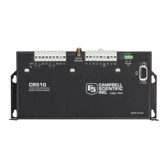
SECTION 6. 9-PIN SERIAL INPUT/OUTPUT 6.1 PIN DESCRIPTION All external communication peripherals connect to the CR510 through the 9-pin subminiature D- type socket connector located on the front of the Terminal Strip (Figure 6.1-1). Table 6.1-1 shows the I/O pin configuration, and gives a brief description of the function of each pin. -
Page 72: Enabling And Addressing Peripherals
CR510 (Section 6.6). 6.3) to come from a modem if the device raises the CR510's Ring line, and holds it high until the Up to 16 SDs may be addressed by the CR510. CR510 raises the ME line. Only one modem/ Unlike an enabled peripheral, the CR510 terminal may be connected to the CR510. -
Page 73: Ring Interrupts
A modem which raises the Ring line will interrupt execution continues. As the 9-pin connector and gain control of the CR510. A ring from a becomes available, each device in the queue will modem aborts data transfer to pin-enabled and get its turn until the queue is empty. -
Page 74: Modem/Terminal Peripherals
6.5 MODEM/TERMINAL PERIPHERALS SD is enabled by an address synchronously The CR510 considers any device with an clocked from the CR510. Up to 16 SDs may be asynchronous serial communications port which addressed by the CR510, requiring only three raises the Ring line (and holds it high until the pins of the 9-pin connector. -
Page 75: Modem/Terminal And Computer Requirements
SDs must drop the Ring line in this state. This transmitted first and is always logic high. Each state is not used by SDs. The CR510 must bit transmitted is stable on the rising edge of force the SDs back to the reset state from State CLK/HS. -
Page 76: Sc32A Pin Description
SECTION 6. 9-PIN SERIAL INPUT/OUTPUT satisfy hardware handshake requirements of TABLE 6.7-1. SC32A Pin Description the computer/terminal. PIN = Pin number Table 6.7-2 lists the most common RS232 Signal Out of the SC32A to a peripheral configuration for Data Terminal Equipment. Signal Into the SC32A from peripheral 25-PIN FEMALE PORT: TABLE 6.7-2. - Page 77 0 to make the parity of the character from such a modem, especially when implemented correct. The CR510 ignores the 8th bit of a by computer software. character that is received, and transmits the 8th To overcome the limitations of half duplex, bit as a binary 0.
- Page 78 If you are using a computer to communicate with the datalogger, communication software If the CR510 is connected to the SC32A RS232 must be used to enable the serial port and to interface and a modem/terminal, and an " " is make the computer function as a terminal.
-
Page 79: Single-Ended Voltage 107 Temperature Probe
SECTION 7. MEASUREMENT PROGRAMMING EXAMPLES This section gives some examples of Input Programming for common sensors used with the CR510. These examples detail only the connections, Input, Program Control, and Processing Instructions necessary to perform measurements and store the data in engineering units in Input Storage. Output Processing Instructions are omitted (see Section 8 for some processing and program control examples). -
Page 80: Typical Connection For Active Sensor With External Battery
Ground at the LI-6262 is 0.065 V higher than ground Instruction 4 is used to measure relative at the CR510. The LI-6262 can be programmed to humidity. It provides an excitation voltage to output a linear voltage (0 to 100 mV) that is power the RH sensor. -
Page 81: Anemometer With Photochopper Output
Do (P86) window chopper wheel. The photochopper 1: 41 Set Port 1 High circuitry is powered from the CR510 12 V supply; AC power or back-up batteries should be used to Excitation with Delay (P22) compensate for the increased current drain. -
Page 82: Tipping Bucket Rain Gage With Long Leads
-10 to measured by the gage (assuming there were 40 C. The length of the cable from the CR510 counts in the long intervals). Output is desired to the PRT is 500 feet. -
Page 83: Wiring Diagram For Prt In 4 Wire Half Bridge
If the actual resistances were the nominal fixed resistor will limit the error due to its change values, the CR510 would not over range with V in resistance with temperature to less than = 2.2 V. To allow for the tolerances in the actual resistances, it is decided to set V equal to 2.1... -
Page 84: Ohm Prt In 3 Wire Half Bridge
The 3 wire half bridge compensates for lead wire resistance by assuming that the resistance of wire A is the same as the resistance of wire B. The maximum difference expected in wire CR510 FIGURE 7.7-1. 3 Wire Half Bridge Used to Measure 100 ohm PRT... -
Page 85: Ohm Prt In 4 Wire Full Bridge
SECTION 7. MEASUREMENT PROGRAMMING EXAMPLES CR510 FIGURE 7.8-1. Full Bridge Schematic for 100 ohm PRT PROGRAM The resistance of the PRT (R ) is calculated with the Bridge Transform Instruction 59: 3W Half Bridge (P7) Reps X'/(1-X') 25 mV 60 Hz Rejection... -
Page 86: Pressure Transducer - 4 Wire Full Bridge
25 mV input range. The sensor is The relationship between temperature and PRT calibrated by connecting it to the CR510 and using resistance is slightly nonlinear one. Instruction Instruction 6, an excitation voltage of 2500 mV, a... -
Page 87: Lysimeter - 6 Wire Full Bridge
31,416 cm , so 1 cm of rainfall or evaporation cell than at the CR510 due to voltage drop in the results in a 31.416 kg change in mass. The load cable. The 6 wire full bridge (Instruction 9) avoids cell can measure ±113.6 kg, a 227 kg range. -
Page 88: Wire Full Bridge Connection For Load Cell
1 mm voltage at the CR510 multiplied by the ratio of the diurnal change in the recorded water content that load cell resistance, R... -
Page 89: Gypsum Soil Moisture Block
Mode) is 109. The offset needed to give the desired initial value of 375 mm is 266. However, it The Campbell Scientific 227 Soil Moisture Block is decided to add this offset in a separate uses a Delmhorst gypsum block with a 1 kohm instruction so the result of Instruction 9 can be bridge completion resistor. -
Page 90: Nonlinear Thermistor In Half Bridge
SECTION 7. MEASUREMENT PROGRAMMING EXAMPLES CR510 FIGURE 7.11-1. 6 227 Gypsum Blocks Connected to the CR510 PROGRAM temperature of four 101 Probes (used with the CR21 but usually not the CR510). Instruction 4, Excite, AC Half Bridge (P5) Delay, and Measure, is used because the high... -
Page 91: Water Level - Geokon'svibrating Wire Pressure Sensor
"plucking" and X Loc [ Temp_C_1 ] "pickup" coils and inducing the same frequency F(X) Loc [ Temp_C_1 ] on the lines to the CR510. Instruction 28 then 4: -53.784 accurately measures how much time it takes to 5: 147.97 receive a user specified number of cycles. -
Page 92: Calibration Data For Sensor 3998
SECTION 7. MEASUREMENT PROGRAMMING EXAMPLES FIGURE 7.13-1. A Vibrating Wire Sensor The following calculations are based on using a = P + C ), where Geokon model 4500 Vibrating Wire sensor. An individual multiplier and offset must be = Pressure corrected for temperature, C calculated for each sensor used in a system. - Page 93 Distance is computed by execution following a program compilation. subtracting the Reading from the Offset as shown in Figure 7.13-2. The example assumes the sensor has been connected as shown here. CR510 & AVW1 FIGURE 7.13-2. Well Monitoring Example 7-15...
-
Page 94: Hook Up To Avw1
12 V or 5 V FIGURE 7.13-3. Hook up to AVW1 PROGRAM Polynomial (P55) Reps X Loc [ Temp AVW1 & CR510 USED TO MEASURE 1 F(X) Loc [ Temp GEOKON VIBRATING WIRE SENSOR. 4: -104.78 5: 378.11 * Table 1 Program 6: -611.59... -
Page 95: To 20 Ma Sensor Using Curs100 Terminal Input Module
Z=X+Y (P33) analog input 1. The CURS100 TIM and dew X Loc [ Temp_Comp ] point sensor are wired to the CR510 terminal Y Loc [ Pressure ] strip panel as shown in Figure 7.14-1. Z Loc [ Pressure ] PROGRAM IF (X<=>F) (P89) -
Page 96: Wiring Diagram For Curs100 Terminal Input Module And 4 To 20 Ma Sensor
SECTION 7. MEASUREMENT PROGRAMMING EXAMPLES CR510 CR10X 4 to 20 mA 0.01% Sensor CURS100 FIGURE 7.14-1 Wiring Diagram for CURS100 Terminal Input Module and 4 to 20 mA Sensor. 7-18... -
Page 97: Computation Of Running Average
Block Move (P54) In this example, each time a new measurement No. of Values is made (in this case the CR510 internal First Source Loc [ Temp_i_8 ] Source Step temperature) an average is computed for the 10 most recent samples. -
Page 98: Rainfall Intensity
SECTION 8. PROCESSING AND PROGRAM CONTROL EXAMPLES In the above example, all samples for the Real Time (P77) average are stored in input locations. This is 1: 0110 Day,Hour/Minute necessary when an average must be output with each new sample. In most cases, Sample (P70) averages are desired less frequently than Reps... -
Page 99: Sub 1 Minute Output Interval Synched To Real Time
“-” or “C” while entering the first parameter in Instruction 92. If a counter, CR510 incremented within the program, was used to determine when to set the Output Flag, output would depend on the number of times the table was executed. -
Page 100: Converting 0-360 Wind Direction Output To 0-540 For Strip Chart
0-360 degree input to 0-540. (If you have a 0-540 pot, it can be used with the Z=X (P31) CR510 since the Wind Vector Instruction, 69, 1: 10 X Loc [ 0_540_WD ] will work with this output.) -
Page 101: Use Of 2 Final Storage Areas - Saving Data Prior To Event
SECTION 8. PROCESSING AND PROGRAM CONTROL EXAMPLES End (P95) PROGRAM End (P95) Table 1 Program Execution Interval (seconds) End (P95) Full Bridge (P6) INPUT LOCATIONS Reps ±7.5 mV 60 Hz Rejection Range 2 0_360_WD DIFF Channel 6 0_540_out Excite all reps w/Exchan 1 10 0_540_WD 5: 2500 mV Excitation... -
Page 102: Logarithmic Sampling Using Loops
SECTION 8. PROCESSING AND PROGRAM CONTROL EXAMPLES If Flag/Port (P91) means the instructions in the loop, in this case Do if Flag 1 is High measure and output water level, are executed Then Do every 10 seconds for 10 minutes. Serial Out (P96) The drawdown portion of the test is completed All Data to other FS Area... - Page 103 SECTION 8. PROCESSING AND PROGRAM CONTROL EXAMPLES ;Loop 2, Output every 30 seconds for 20 minutes. If Flag/Port (P91) Do if Flag 1 is Low Beginning of Loop (P87) Exit Loop if True Delay Loop Count End (P95) Table 3 Subroutines Do (P86) Call Subroutine 1 Beginning of Subroutine (P85)
- Page 104 SECTION 8. PROCESSING AND PROGRAM CONTROL EXAMPLES This is a blank page.
-
Page 105: Input/Output Instructions
Both the high and low maximum of 250 kHz. The count is incremented inputs must be within ±2.5 V of the CR510's when input voltage changes from below 1.5 ground (see Common Mode Range in Section... - Page 106 5.6 VDC. and ground (G). When the switch is open, the CR510 pulls the pulse input to 5 volts. When the When this happens, the excess voltage is switch is closed, the pulse input is at ground. The shunted to the CR510 5 VDC supply, with the count is incremented when the switch opens.
-
Page 107: Pulse Count Configuration Codes
SECTION 9. INPUT/OUTPUT INSTRUCTIONS Every 0.125 seconds, the CR510 processor NOTE: All pulse count instructions must be transfers the values from the 8 (or 16) bit pulse kept in the same table. If the Pulse Count counters into 16 bit accumulators (max count is... - Page 108 SECTION 9. INPUT/OUTPUT INSTRUCTIONS PARAM. DATA Input location number NUMBER TYPE DESCRIPTION for first measurement Multiplier Repetitions Offset Range code (Table 9-1) Single-ended channel Input locations altered: 1 number for first measurement *** 6 FULL BRIDGE WITH SINGLE *** Excitation channel DIFFERENTIAL MEASUREMENT number Delay in hundredths of...
- Page 109 SECTION 9. INPUT/OUTPUT INSTRUCTIONS resulting value, which is the ratio of the voltage PARAM. DATA across the sensor to the voltage across the NUMBER TYPE DESCRIPTION reference resistor. A 1 before the excitation Repetitions channel number (1X) causes the channel to be Range code (Table 9-1) incremented with each repetition.
-
Page 110: Excitation/Integration Codes
This instruction reads the battery voltage and *Code (See Table) writes it to an input location. The units for Input location for first battery voltage are volts. At approximately 9.6 measurement V the CR510 suspends measurements. Multiplier Offset PARAM. DATA NUMBER... - Page 111 *** 17 INTERNAL TEMPERATURE *** Curve Fit Error -- FUNCTION Range (%RH) Error (%RH) This instruction measures the temperature (°C) 10 - 100 of a thermistor on the CR510 analog board. 15 - 94 PARAM. DATA PARAM. DATA NUMBER TYPE...
-
Page 112: Port Configuration Option Codes
Toggle port (SRAM) into an input location. The signature is Pulse duration 1 ms a result of the CR510 PROM, the size of SRAM, Pulse duration 10 ms and the entries in the 1, 2, 3, 4, A, and C Pulse duration 100 ms Modes. - Page 113 INPUT LOCATION TO *** 24 CALIBRATION *** STORE RESULT Input locations altered: 1 FUNCTION Put the CR510’s 19 calibration values into input *** 26 TIMER *** locations. If C (--) is keyed before entering the input location, then the automatic calibrations FUNCTION are simply displayed, not measured.
-
Page 114: Input Frequency Codes
1x Output frequency in kHz automatically. 2. Entering " 6" after changing the program where x is range code compiles the programs, but does NOT reset * AC voltage; must be centered around CR510 the timer. ground. PARAM. DATA ** Consult Campbell Scientific if higher NUM. - Page 115 SECTION 9. INPUT/OUTPUT INSTRUCTIONS PARAM. DATA Enhanced Parameter 6 NUMBER TYPE DESCRIPTION Enhanced Parameter 7 Enhanced Parameter 8 Repetitions Hit C (--) to Enhanced Parameter 9 skip repeat of Enhanced Parameter 10 excitation Enhanced Parameter 11 Single-ended channel Enhanced Parameter 12 for first measurement Enhanced Parameter 13 Excitation Channel...
- Page 116 (see Appendix C). For example, address ‘A’ elapsed time is equal to or greater than that would be entered as 65, and address ‘z’ would given by the sensor, the CR510 will get the data be entered as 122. from the SDI-12 sensor. In the following execution of the instruction, the CR510 will PARAMETER 2.
- Page 117 The SDI-12 data line is attached to Control Port telecommunications with the SDI-12 recorder 2 and Instruction 106 must be the first CR510 (at the asterisk ' ' prompt). Enter 'pX' at instruction in Subroutine 98 located in Table 3. An SDI-12 recorder addresses the SDI-12...
- Page 118 PARAMETER 1. ADDRESS The second technique transfers measurement Enter the address for the CR510 acting as an values previously obtained by instructions in SDI-12 sensor (0-9, †10-126 decimal value for Table 1 or Table 2. Subroutine 98 contains only ASCII character, see Appendix E).
- Page 119 PARAM DATA NUMBER TYPE DESCRIPTION The sensor CR510 will return a set of input locations in response to the M or M1..M9 Input location number command sequence. The set of Locations returned is determined by Parameters 2 and 3 *** 130 Error Monitor *** of Instruction 106.
- Page 120 SECTION 9. INPUT/OUTPUT INSTRUCTIONS PARAM DATA *** 131 Enhanced Vibrating Wire NUMBER TYPE DESCRIPTION Measurement *** Repetitions (Index (- - ) FUNCTION to skip repeat of Excites a vibrating wire sensor with a swept excitation) frequency (from low frequency to high), then Single-ended channel measures the response period and calculates for first measurement...
- Page 121 SECTION 10. PROCESSING INSTRUCTIONS To facilitate cross referencing, parameter PARAM. DATA descriptions are keyed [ ] to the values given on NUMBER TYPE DESCRIPTION the PROMPT SHEET. These values are Destination input defined as follows: location [Z] = Destination input location for result Input locations altered: [X] = Input location of X [Y] = Input location of Y...
- Page 122 Dest. input for EXP(X) FUNCTION Divide X by Y and place the result in an input location. Division by 0 will cause the result to be Input locations altered: set to the maximum CR510 number (99999). *** 42 1/X *** PARAM. DATA NUMBER...
- Page 123 SECTION 10. PROCESSING INSTRUCTIONS PARAM. DATA *** 43 ABS(X) *** NUMBER TYPE DESCRIPTION FUNCTION Input location of X Take the absolute (ABS) value of X and place Fixed divisor the result in an input location. Dest. input loc. For X PARAM.
- Page 124 SECTION 10. PROCESSING INSTRUCTIONS Parameter 3 cannot be entered as an indexed PARAM. DATA location within a loop (Instruction 87). To use NUMBER TYPE DESCRIPTION Instruction 49 within a loop, enter Parameter 3 Swath [SWATH] as a fixed location and follow 49 with the Instruction 31 (Move Data).
- Page 125 *** 55 5TH ORDER POLYNOMIAL *** where X is the SVPW derived by Instruction 56. FUNCTION This relationship was derived by Campbell Evaluate a 5th order polynomial of the form Scientific from the equations for the SVPW and the SVPI given in Lowe's paper.
- Page 126 R which is equivalent to [X/(1-X)], where X is the value derived by the 01:-08: Depends upon preceding standard CR510 Bridge Measurement instruction. Following Instructions (with appropriate multiplier and Instruction 97 RF IDs offset, Section 13.5) and R represents the and Phone No.
-
Page 127: Quadrant That The Angle Falls In Is Defined By The Sign Of X And Y
SECTION 10. PROCESSING INSTRUCTIONS and 13 To END. Following Instruction 98 (255 character limit) Base 10 value of ASCII character (Appendix E) 00 TO END. Input locations altered: *** 65 BULK LOAD *** FUNCTION Instruction 65 inputs given values in up to eight Input Storage locations. - Page 128 SECTION 10. PROCESSING INSTRUCTIONS This is a blank page. 10-8...
-
Page 129: Output Processing Instructions
SECTION 11. OUTPUT PROCESSING INSTRUCTIONS Standard deviation of horizontal wind *** 69 WIND VECTOR *** fluctuations from sub-intervals is calculated as follows: FUNCTION Instruction 69 processes the primary variables of wind speed and direction from either polar ( )=[(( ...+( )/M] (wind speed and direction) or orthogonal (fixed East and North propellers) sensors. - Page 130 Resultant mean wind direction, u. Standard deviation of wind direction, ( u). Ue=( S Un=( S This standard deviation is calculated using Campbell Scientific's wind speed weighted or, in the case of orthogonal sensors: algorithm. Ue=( Ue Use of the Resultant mean horizontal wind...
- Page 131 SECTION 11. OUTPUT PROCESSING INSTRUCTIONS *** 71 AVERAGE *** *** 74 MINIMIZE *** FUNCTION FUNCTION This instruction stores the average value over Operating in the same manner as Program 73, the given output interval for each input location this instruction is used for storing the MINIMUM specified.
- Page 132 SECTION 11. OUTPUT PROCESSING INSTRUCTIONS while the bin select value was within a particular PARAM. DATA sub-range, the value output to Final Storage NUMBER TYPE DESCRIPTION must be divided by the fraction of time that the Repetitions bin select value was within that particular sub- range (i.e., a standard histogram of the bin Number of bins select value must also be output).
- Page 133 SECTION 11. OUTPUT PROCESSING INSTRUCTIONS PARAM. DATA Code Result NUMBER TYPE DESCRIPTION xxx1 SECONDS (with resolution of 0.125 sec.) Repetitions (number of xx1x HOUR-MINUTE sequential locations to xx2x HOUR-MINUTE, 2400 instead of 0000 sample) x1xx JULIAN DAY x2xx JULIAN DAY, previous day during first Starting input location no.
- Page 134 SECTION 11. OUTPUT PROCESSING INSTRUCTIONS PARAM. DATA NUMBER TYPE DESCRIPTION Repetitions Starting input location no. Outputs Generated: 1 per repetition 11-6...
-
Page 135: Program Control Instructions
NOTE: If Control Port 2 is used for pulse PARAM. DATA measurements or interrupt subroutines, the NUMBER TYPE DESCRIPTION CR510 will not go into the quiescent power Fixed value state (0.7 mA), if Control Ports 2 is high. Command PARAM. DATA *** 85 LABEL SUBROUTINE ***... - Page 136 If the input location is indexed, the When the loop is first entered, one pass through values from all input locations are added to the the loop is made, then the CR510 delays until same total. the next execution interval and makes the second pass through the loop.
-
Page 137: Comparison Codes
(Table 12-3) that they are within. The maximum nesting Fixed value level in the CR510 is 11 deep. This applies to If Command (Table 12-2) Then/Else comparisons and Loops or any combination thereof. An If Then/Else... - Page 138 SECTION 12. PROGRAM CONTROL INSTRUCTIONS *** 92 IF TIME *** *** 93 BEGIN CASE STATEMENT *** FUNCTION The value in the specified input location is The user specifies the number of minutes or compared against parameters in following If seconds into an interval, the duration of the Case instructions (83).
-
Page 139: Baud Rate Codes
Input Storage, in which case Instruction 96 76800 with checksum assumes Final Storage Area 1. PARAM. DATA If the CR510 is already communicating on the NUMBER TYPE DESCRIPTION 9-pin connector when Instruction 96 is executed, the output request is put in a queue Option Device and program execution continues. - Page 140 Once a successful call is made, the Failure TELECOMMUNICATIONS Input Location is reset to 0. Instruction 97 is used to have the CR510 initiate Be careful in calling P97 from a conditional telecommunications in response to certain statement or subroutine. Instruction 7 must be conditions.
- Page 141 ID# is not received by the CR510 Parameter 4: within the time allotted in parameter 3, the The CR510 will repeat the call at a fast interval datalogger hangs up and waits for the time for specified by Parameter 4 (in 1 sec. units).
-
Page 142: Option Code For Modem Type And Baud Rate
FUNCTION ID to send This instruction is used to transmit data from CR510 Final Storage via a GOES satellite to a *** 98 SEND CHARACTER *** central ground station. See the TGT1 manual for information on Instruction 120. Instruction 98 is used with Instruction 63 to send a character or string of characters (up to 15) to the printer. - Page 143 SECTION 12. PROGRAM CONTROL INSTRUCTIONS *** 121 ARGOS *** FUNCTION This instruction is used to transmit data from CR510 Final Storage via an ARGOS satellite. See the ARGOS Interface Notes for information on Instruction 121. *** 123 Automatic Programming of a TGT1 ***...
- Page 144 SECTION 12. PROGRAM CONTROL INSTRUCTIONS This is a blank page. 12-10...
-
Page 145: Fast And Slow Measurement Sequence
A/D conversion. There rate. The current drain on the CR510 batteries are two integration times which can be specified is lower when the fast integration time is used. -
Page 146: Single-Ended And Differential Voltage Measurements
CR510 ground, any difference in DIFFERENTIAL VOLTAGE ground potential between the sensor and the MEASUREMENTS CR510 will result in an error in the measurement. For example, if the measuring NOTE: Either the high or low side of a junction of a copper-constantan thermocouple,... -
Page 147: The Effect Of Sensor Lead Length On The Signal Settling Time
(explained good ground connection exists through the AC below). The CR510 allows a 450 µs settling wiring. If a CR510 is used to measure the time before initiating the measurement. In most output from a laboratory instrument (both... -
Page 148: Cr510 Measurements
(t/ ) are contained in The settling time constant, in seconds, and the the 450 µs CR510 input settling interval (t). The capacitance relationships are given in familiar exponential decay relationship is given Equations 13.3-3 through 13.3-5,... -
Page 149: Typical Resistive Half Bridge
FIGURE 13.3-2. Typical Resistive Half Bridge CR510 HI OR LO INPUT FIGURE 13.3-3. Source Resistance Model for Half Bridge Connected to the CR510 The source resistance for several Campbell DETERMINING SOURCE RESISTANCE Scientific sensors are given in column 3 of The source resistance used to estimate the Table 13.3-5. -
Page 150: Properties Of Three Belden Lead Wires Used By Campbell Scientific
SECTION 13. CR510 MEASUREMENTS FIGURE 13.3-4. Wire Manufacturers Capacitance Specifications, C CR510 FIGURE 13.3-5. Model 024A Wind Direction Sensor TABLE 13.3-2. Properties of Three Belden Lead Wires Used by Campbell Scientific Belden Wire # Conductors Insulation (ohms/1000ft.) (pfd/ft.) 8641 1 shld. pair... -
Page 151: Settling Error, In Degrees, For 024A Wind Direction Sensor Vs. Lead Length
SECTION 13. CR510 MEASUREMENTS CR510 FIGURE 13.3-6. Resistive Half Bridge Connected to Single-Ended CR510 Input , the source resistance, is not constant TABLE 13.3-3. Settling Error, in Degrees, for because R varies from 0 to 10 kohms over the 024A Wind Direction Sensor vs. Lead Length 0 to 360 degree wind direction range. -
Page 152: Measured Peak Excitation Transients For 1000 Foot Lengths Of Three Belden Lead Wires Used By Campbell Scientific
2) V ~ 2.5 µV, allowable measurement error independent from the signal leads. 3) t = 450 µs, CR510 input settling time The size of the peak transient is linearly related to the excitation voltage and increases as the 4) R... -
Page 153: Summary Of Input Settling Data For Campbell Scientific Resistive Sensors
8771 1-222 0-90 Estimated time constants are for 1000 foot lead lengths and include 3.3nfd CR510 input capacitance. ** Measured peak transients for 1000 foot lead lengths at corresponding excitation, V TABLE 13.3-6. Maximum Lead Length vs. Error for Campbell Scientific Resistive Sensors... -
Page 154: Source Resistances And Signal Levels For Ysi #44032 Thermistor
Converting the error to C gives approximately a 0.33= C error at 0 C, 5. Use the CR510 to measure the input 0.53 C error at 20 C, and a 0.66 C error at settling error associated with a given 40 C. -
Page 155: Half Bridge Configuration For Ysi #44032 Thermistor Connected To Cr510
SECTION 13. CR510 MEASUREMENTS FIGURE 13.3-7. Half Bridge Configuration for YSI #44032 Thermistor Connected to CR510 Showing: A) large source resistance, B) large source resistance at point P, and C) configuration optimized for input settling 13-11... -
Page 156: Bridge Resistance Measurements
SECTION 13. CR510 MEASUREMENTS CR510 FIGURE 13.3-8. Measuring Input Settling Error with the CR510 CR510 FIGURE 13.3-9. Incorrect Lead Wire Extension on Model 107 Temperature Sensor in the two measurements due to thermal emfs 13.4 BRIDGE RESISTANCE can then be accounted for in the processing of MEASUREMENTS the measurement instruction. - Page 157 SECTION 13. CR510 MEASUREMENTS integration as is normally the case (Section channel number (1X) causes the channel to be 13.2). The result stored is the voltage incremented with each repetition. measured. Instruction 8 does not have as good resolution or common mode rejection as the The output of Instruction 8 is simply the voltage ratiometric bridge measurement instructions.
-
Page 158: Comparison Of Bridge Measurement Instructions
SECTION 13. CR510 MEASUREMENTS FIGURE 13.4-2. Excitation and Measurement Sequence for 4 Wire Full Bridge TABLE 13.4-1. Comparison of Bridge Measurement Instructions Instr. # Circuit Description Instr. # Circuit Description DC Half Bridge The delay parameter 3 Wire Compensates for lead... -
Page 159: Calculating Resistance Values From Bridge Measurement
SECTION 13. CR510 MEASUREMENTS Calculating the actual resistance of a sensor multiplier and stores the result in the original which is one of the legs of a resistive bridge location. Instruction 42 computes the reciprocal usually requires the use of one or two Processing of a value in an input location. -
Page 160: Resistance Measurements Requiring Ac Excitation
247 conductivity probe) reverses because the soil and water provide an alternate excitation polarity to provide ion depolarization path for the excitation to return to CR510 and, in order to minimize the time excitation is ground, and can be represented by the model on, grounds the excitation as soon as the signal diagrammed in Figure 13.5-2. -
Page 161: Calibration Process
R is the resistance between the excited maintained over the -25 to +50 C operating electrode and CR510 earth ground. With R range of the CR510. Calibration is executed the network, the measured signal is: under four conditions: 1. - Page 162 If the measurements are that the instruction is executed. For example, being averaged, the effect of the overrun is consider a CR510 mounted under the dash of negligible. Program table overruns are an automobile, where temperature could easily indicated by the appearance of two decimals on change 50 degrees.
-
Page 163: Protection From The Environment
The CR510 operates at a nominal 12 VDC. board. Extra desiccant should also be placed in Below 9.6 or above 18 volts the CR510 does the enclosure to prevent corrosion. not operate properly. Campbell Scientific offers fiberglass enclosures The CR510 is diode protected against for housing a CR510 and peripherals. -
Page 164: Campbell Scientific Power Supplies
AC or DC power, limits (amp-hours) by the average system current current from the battery, and provides circuitry drain. The CR510 draws <1 mA in the to connect an external 12 volt battery. quiescent state, 13 mA while processing, and 46 mA during an analog measurement;... -
Page 165: Typical Alkaline Battery Service And Temperature
12 V is shorted to either of these, excessive connected to the PS12 at all times. The current will be drawn until the thermal fuse charging source powers the CR510 while float opens. charging the lead acid batteries. The internal... -
Page 166: Ps12La, Battery, And Ac Transformer Specifications
NULL MODEM PORTS External power sources must be disconnected The PS512M 12 Volt Lead Acid Power Supply from the CR510 and charging circuit in order to with Charging Regulator and Null Modem Ports measure the actual lead acid battery voltage. -
Page 167: Solar Panels
If a CR510 is to be powered from the 12 Volts of a motor vehicle, a second 12 V supply is also Guidelines are available from the Solarex required at the time of vehicle start-up. -
Page 168: Grounding
SECTION 14. INSTALLATION AND MAINTENANCE directed away from the CR510 through the 14.7 GROUNDING diodes. The fuse may be replaced by soldering 14.7.1 PROTECTION FROM LIGHTNING another 30 AWG wire to the soldering pads provided. Primary lightning strikes are those where lightning hits the datalogger or sensors directly. -
Page 169: Terminal Strip
The Terminal Strip carries two lines between through a grounding rod. A 12 AWG or larger the CR510 and each excitation port. One line is wire should be run between a Terminal Strip for excitation voltage, the other is for feedback power ground (G) terminal and the earth control of the voltage. -
Page 170: Relay Driver Circuit With Relay
SECTION 14. INSTALLATION AND MAINTENANCE CONTROL PORT FIGURE 14.9-1. Relay Driver Circuit with Relay CONTROL PORT FIGURE 14.9-2. Power Switching without Relay 14-8... -
Page 171: Maintenance
14.10.2 REPLACING THE INTERNAL BATTERY The CR510 contains a lithium coin cell battery that operates the clock and SRAM when the CR510 is not connected to an external power source. - Page 172 SECTION 14. INSTALLATION AND MAINTENANCE This is a blank page. 14-10...
-
Page 173: Glossary
When not used as a characters/sec. When communicating via a clock line, the CLK/HS (pin 7) line in the CR510 serial interface, the baud rate settings of two is primarily used to detect the presence or pieces of equipment must match each other. - Page 174 MODEM/TERMINAL: Any device which: 1) Program Table, the CR510 will prompt for the has the ability to raise the CR510's ring line or parameters by displaying the parameter number be used with the SC32A to raise the ring line in the ID Field of the display.
- Page 175 Final scaled to engineering units, and the reading Storage. Programming can be separated into 2 stored in Final Storage. The CR510 has the tables, each having its own user-entered ability to scan sensors at a rate exceeding the Execution Interval.
- Page 176 APPENDIX A. GLOSSARY This is a blank page.
-
Page 177: Telecommunications Command With Binary Responses
J command data in CSI's binary format if requested by or telecommunications is terminated. Currently the J command, and terminating in 7F 00 only the CR510 datalogger recognizes this bit. HEX and two signature bytes. The remaining bits are reserved. - Page 178 Multiply Bit Value by 0.5. The optional ports byte (currently on return if End of loop. requested by a CR510 J command) expresses the datalogger port status. The most significant Another method that can be used as an bit represents Port 8, and so on to the least estimate is to convert Data bytes 2 to 4 from a significant bit which represents Port 1.
-
Page 179: Final Storage Format
Data byte 1 = 44 HEX. B.2 FINAL STORAGE FORMAT Data byte 2 to 4 = D9 99 9A HEX (or 891290 CR510 data is formatted as either 2 byte LOW decimal). Resolution or 4 byte HI Resolution values. The... - Page 180 A,B = 0; C = 1 - Third byte of a 4 byte value. A = 0; remaining bits = 1 - First byte of a 2 byte "dummy" word. The CR510 always transmits a 0 for the 2nd byte, but the word can be decoded on the basis of the 1st byte only.
-
Page 181: Generation Of Signature
If the keyboard display is not being used, itself. By calculating the signature of the the CR510 will have already set the baud rate to received data and comparing it to the that of the device it is communicating with and will... - Page 182 If the signature is correct, LOAD PROGRAM FROM ASCII FILE ^D ^D can be sent to tell the CR510 to load the Command 2 sets up the CR510 to load a buffer into the editor and reset the signature.
-
Page 183: Ascii Table
APPENDIX C. ASCII TABLE American Standard Code for Information Interchange Decimal Values and Characters (X3.4-1968) Dec. Char. Dec. Char. Dec. Char. Dec. Char. CONTROL @ SPACE CONTROL A CONTROL B " CONTROL C CONTROL D CONTROL E CONTROL F & CONTROL G CONTROL H CONTROL I... - Page 184 This is a blank page.
-
Page 185: Introduction
Datalogger initiated communications, commonly referred to as “callback," is when the datalogger initiates a call back to a computer. A CR510 uses Instruction 97 to initiate a call. For complete information on Instruction 97 and its parameters, refer to section 12. -
Page 186: Pc208 Dos Computer Software And It's Computer Setup
APPENDIX D. DATALOGGER INITIATED COMMUNICATIONS 6: Do (P86) 15: Extended Parameters (P63) Set Port 1 Low Option Option Option 7: If time is (P92) Option Minutes (Seconds --) into a Option Interval (same units as above) Option Set Output Flag High Option Option 8: Real Time (P77) - Page 187 You may name the file anything you want, but it Telecommunications Program ver. 7.3 must have the extension of .SCR. The .SCR Copyright (C) 1986,1991 Campbell Scientific, Inc. file is the same for TELCOM or PC208E (Figure Executing script file "C:\PC208\CALLME12"...
- Page 188 APPENDIX D. DATALOGGER INITIATED COMMUNICATIONS This is a blank page.
-
Page 189: Introduction
Section E.2 covers programming requirements datalogger. This should not be confused with for the calling CR510. Section E.3 shows the the flag that the calling datalogger sets in the programming requirements for the remote remote datalogger (specified in Instruction 63). - Page 190 Instruction 63 is used to specify the dialing path datalogger at phone number '”539” every 2 and special options for Instruction 97. More minutes. The CR510 toggles Flag 1 in the than one Instruction 63 may be required. remote datalogger to trigger measuring and Instruction 68 may be used instead of data collection.
-
Page 191: Remote Datalogger Programming
2 minutes at using the RF to detect when the specified flag is set high. Path of “4 10F” (that is from the calling CR510 When the flag is set high, measurements and to RF ID# 4 to RF ID# 10 at the remote site). - Page 192 APPENDIX E. CALL ANOTHER DATALOGGER VIA PHONE OR RF Panel Temperature Loc : Temp 107 Probe IN Chan Excite all reps w/EXchan 1 Loc : Mult Offset Set low Flag 1 End Table 1...
-
Page 193: Terminology
Modbus communication capability is available as a Library Special on the CR10(X) and CR510 dataloggers. The implementation of MODBUS on the CR10(X) and CR510 allows input locations, ports, and flags to be read or to be set. Not supported are historical data retrieval, program downloads, setting the clock, and other functions of PC208. -
Page 194: F.3 More On Modbus
Coil 15 is the Most Significant Bit Following is a brief explanation of the modbus (MSB). The CR510’s C1 is on, C2, C5, and C6 functions supported and the strings that are are off. Flags 1,2,4,6, and 7 are high. - Page 195 APPENDIX F. MODBUS ON THE CR10(X) AND CR510 The register data is returned as two bytes per register and two registers per input location. Response for example 2: Slave address Function Byte Count Data Hi (Register 40009) Data Lo (Register 40009)
- Page 196 APPENDIX F. MODBUS ON THE CR10(X) AND CR510 This is a blank page.
- Page 197 APPENDIX G. TD OPERATING SYSTEM ADDENDUM FOR CR510, CR10X, AND CR23X MANUALS...
- Page 198 This is a blank page.
-
Page 199: Td Operating System Addendum For Cr510, Cr10X, And Cr23X Manuals
TD OPERATING SYSTEM ADDENDUM FOR CR510, CR10X, AND CR23X MANUALS REVISION: 1/03 COPYRIGHT 2002-2003 CAMPBELL SCIENTIFIC, INC. - Page 200 This is a blank page.
- Page 201 TABLE DATA ADDENDUM TD and PakBus Operating System Addendum for CR510, CR10X, and CR23X Manuals AD1 Major Differences Table Data (TD) operating systems have two major differences from the standard operating systems: First - the namesake - in the way data are stored internally and second, in the options available for transferring that data to external devices.
- Page 202 TABLE DATA ADDENDUM AD2 Overview of Data Storage Tables Within a data table, data is organized in records and fields. Each row in a table represents a record and each column represents a field. To understand the concept of tables it may be helpful to consider an example. A CR10-TD is to be used to monitor 3 thermocouples (TC).
- Page 203 TABLE DATA ADDENDDUM • Check the Maximum and Minimum Instructions (Instructions 73 and 74) as there is only one option to store time with the value. • Edit Input Location labels removing all spaces and special characters. Only letters, numbers, and the “_” characters are allowed.
- Page 204 Section 5 TD operating system is different than that of the standard operating systems. Campbell Scientific provides software for communications; a description of the protocol is beyond the scope of this addendum. Many of the peripherals discussed in section 6 are not supported by Section 6 the TD operating system.
- Page 205 TABLE DATA ADDENDDUM The TD operating system does not use the output Flag 0. Section 12 Commands dealing with it are not valid. Instruction 92 – There is no option for minutes, time is in seconds only. Instructions Not In TD OS: Instruction 96 –...
- Page 206 TABLE DATA ADDENDUM This is a blank page. AD-6...
- Page 207 MEASUREMENT AND CONTROL MODULE OVERVIEW While this section of the addendum references the CR10X, everything but the measurement instructions in the example programs applies to the other dataloggers as well. Table OV3.2-1 in the CR10X Manual is incorrect for the TD operating system. See Table OV4.1-1 below. The following sections OV4, OV5, and OV6 replace those in the CR10X Manual.
- Page 208 TD ADDENDUM—OVERVIEW TABLE OV4.2-2. Additional Keys Allowed in NOTE: The program must be executed for Telecommunications output to occur. Therefore, the interval specified with the Data Table Instruction is Action set must be evenly divisible by the execution Change Sign, Index (same as C) interval.
- Page 209 HELLO On power-up, the CR10X EDLOG is a prompting editor for writing and displays "HELLO" while it checks documenting programs for Campbell Scientific the memory (this display occurs CR10X dataloggers. Program files developed only with the CR10KD). with EDLOG can be downloaded directly to the after a few seconds delay CR10X using NetAdmin.
- Page 210 TD ADDENDUM—OVERVIEW (ID:Data) Explanation LOG 1 Exit Table 1, enter *0 Mode, compile table and begin logging. 06:0000 Enter *6 Mode (to view Input Storage). 01:21.234 Advance to first storage location. Panel temperature is 21.234°C (the display will show the actual temperature).
- Page 211 To make thermocouple measurements with the CR10X, The first example described program entry one purchase the Campbell Scientific Thermocouple keystroke at a time. This example does not Reference, Model CR10XCR (Section 13.4) and show the "A" key. Remember, "A" is used to make the reference temperature measurement enter and/or advance (i.e., between each line in...
- Page 212 TD ADDENDUM—OVERVIEW SAMPLE PROGRAM 2 Instruction # Parameter (Loc:Entry) (Par#:Entry) Description Enter Program Table 1 01:60 60 second (1 minute) execution interval Key "#D" repeatedly until 01:P00 Erase previous Program before continuing. is displayed 01:P17 Measure internal temperature 01:1 Store temp in Location 1 02:P14 Measure thermocouple temperature (differential) 01:1...
- Page 213 TD ADDENDUM—OVERVIEW The program to make the measurements and send the desired data to Final Storage has been entered. The program is complete. The clock must now be set so that the date and time tags are correct. (Here the example reverts back to the key by key format.) Display Explanation 00:21:32...
- Page 214 2. THE DSP4 HEADS UP DISPLAY ALLOWS THE USER TO VIEW DATA IN INPUT STORAGE. ALSO BUFFERS FINAL STORAGE DATA AND WRITES IT TO CASSETTE TAPE, PRINTER OR STORAGE MODULE. 3. ALL CAMPBELL SCIENTIFIC RS-232 INTERFACES HAVE A FEMALE 25 PIN RS-232 CONNECTOR. FIGURE OV6.1-1. Data Retrieval Hardware Options...
- Page 215 SECTION 1. FUNCTIONAL MODES Sections 1.5 and 1.8 are replaced by the following sections. 1.5 MEMORY ALLOCATION - ∗A Intermediate Storage is a scratch pad for Output Processing Instructions. It is used to 1.5.1 INTERNAL MEMORY store the results of intermediate calculations necessary for averages, standard deviations, When powered up with the keyboard display histograms, etc.
- Page 216 TD ADDENDUM SECTION 1. FUNCTIONAL MODES Flash Memory SRAM (EEPROM) How it works: Total 128 Kbytes The Operating System is loaded into Flash Memory at the factory. System Operating System Memory is used while the CR10X is 32K SRAM running for calculations, buffering data (96 Kbytes-CR10X) Main Memory...
- Page 217 TD ADDENDUM SECTION 1. FUNCTIONAL MODES TABLE 1.5-2. Description of ∗A Mode Data Keyboard Display Entry ID: Data Description of Data ∗ 01: XXXX Input Storage Locations (minimum of 28, maximum of 6655, but the usable maximum is less than this because intermediate and program storage require some of this memory).
-
Page 218: D Mode Commands
TD ADDENDUM SECTION 1. FUNCTIONAL MODES to which memory is cleared on powerup, to set TABLE 1.8-3 Deleting Current Datalogger the PakBus ID, and to set communication to full Program or half duplex. Key entry Display ∗D 13:00 CSI datalogger support software makes use of the ∗D Mode to upload and download programs from a 07:00 computer. - Page 219 TD ADDENDUM SECTION 1. FUNCTIONAL MODES 1.8.6 SET INITIAL BAUD TABLE 1.8-11. PakBus Address and Routing Table Table 1.8-10 shows the option codes available for setting the initial baud rate. Setting the initial baud rate forces the CR10X to try the selected Entry Display Comments...
- Page 220 TD ADDENDUM SECTION 1. FUNCTIONAL MODES The *D15 entries are sent when the program is 1.8.11 SET PAKBUS ROUTER BEACON retrieved. They can also be set like other *D INTERVAL settings via the DLD file. TABLE 1.8-13. Set Beacon interval 1.8.9 ALLOCATE MEMORY FOR GENERAL PURPOSE FILES Entry...
- Page 221 TD ADDENDUM SECTION 1. FUNCTIONAL MODES 1.9 *9 DATA TABLES SIZES. TABLE 1.8-14. Set PakBus Neighbors The *9 Mode is used to view the sizes of the Data Storage Tables (section 2.1) created by Entry Display Comments the datalogger program (*1, *2, or *3). The *9 Mode will also display how long until any 13:00 Enter Command...
- Page 222 TD ADDENDUM SECTION 1. FUNCTIONAL MODES This is a blank page. AD-1-8...
- Page 223 THIS SECTION ENTIRELY REPLACES THE DATALOGGER MANUAL SECTION 2. SECTION 2. INTERNAL DATA STORAGE temperature data for the first thermocouple is 2.1 FINAL STORAGE AND DATA referenced as "HOURLY.TEMP1." As Data Tables TABLES are allocated in the datalogger program, some Final Storage is that portion of memory where Final Storage Memory is reallocated for the final processed data are stored.
- Page 224 TD ADDENDUM—SECTION 2. INTERNAL DATA STORAGE • Storage − Number of Final Storage Locations The output interval is not an even multiple of the scan rate (table execution interval). available for Data Storage Tables. Section 1.5.2 • Table execution is such that Instruction 84 Tables −...
- Page 225 2.2 DATA OUTPUT FORMAT AND 0.0086731924 is better than 0.000000001. RANGE LIMITS Data is stored internally in Campbell Scientific's A precise calculation of the resolution of a Binary Final Storage Format (Appendix C.2). number may be determined by representing the Data may be sent to Final Storage in either number as a mantissa between .5 and 1...
-
Page 226: Mode Command Summary
TD ADDENDUM—SECTION 2. INTERNAL DATA STORAGE records long is maintained inside Intermediate TABLE 2.3-1. *7 Mode Command Summary Storage to keep track of "holes" in the recorded data, due to watch dog errors or clock changes, ACTION so that the time of each record can be implicitly "Advances"... -
Page 227: Error Codes
SECTION 3. INSTRUCTION SET BASICS Section 3.7.1 does not apply to the TD operating system which does not use Output Flag 0. Table 3.8-1 Valid Flag Commands are 11 – 19 to set high and 21- 29 to set low. Because the TD operating system does not use Flag 0, Commands 10 and 20 are not valid with the TD operating system. - Page 228 TD ADDENDUM—SECTION 3. INSTRUCTION SET BASICS Program Program Storage Area Transfer full Program Program does not exist in Transfer Flash memory Program Addressed Transfer device not connected Program Data not received within Transfer 30 seconds Program Uncorrectable errors Transfer detected Program Wrong file type or editor Transfer...
-
Page 229: Processing And Program Control Examples
SECTION 8. PROCESSING AND PROGRAM CONTROL EXAMPLES This section contains examples for the CR10X. The appropriate voltage range codes would have to be selected for the CR23X (see CR23X Manual Section 8 for the measurement instructions). The CR510- TD may not support all the examples. - Page 230 TD ADDENDUM—SECTION 8. PROCESSING AND PROGRAM CONTROL EXAMPLES Data Table First Loc AVG_i2 Seconds into interval Avg Loc [:Avg_3_HR ] Every time Data Table Records (0=auto; -=redirect) Seconds into interval Sample 02: 3600 Seconds interval Reps Records (0=auto; -=redirect) Loc smpl10avg Sample End Table 1 Reps...
- Page 231 TD ADDENDUM—SECTION 8. PROCESSING AND PROGRAM CONTROL EXAMPLES If time is gradients. A 107 Temperature Probe is seconds into a centrally located on the multiplexer board and second interval used as a thermocouple temp. reference. Set high Flag 1 The AM416 switches the 223 moisture block Data Table out of the circuit when it is not being measured.
- Page 232 TD ADDENDUM—SECTION 8. PROCESSING AND PROGRAM CONTROL EXAMPLES FIGURE 8.3-1. AM416 Wiring Diagram For Thermocouple and Soil Moisture Block Measurements EXAMPLE PROGRAM MULTIPLEXING THERMOCOUPLES AND SOIL MOISTURE AC Half Bridge BLOCK 250 mV fast Range IN Chan Table 1 Programs Excite all reps w/EXchan 1 Sec.
-
Page 233: Connections For Rain Gage
TD ADDENDUM—SECTION 8. PROCESSING AND PROGRAM CONTROL EXAMPLES Input location Assignments: 8.4 INTERRUPT SUBROUTINE USED TO COUNT SWITCH CLOSURES 10:Rain_1 (from Pulse count) 11:Rain_2 (from Pulse count) (RAIN GAGE) 12:Rain_3 (from subroutine 98 while Subroutines given the label of 97 or 98 will be Output Flag is low) executed when control ports 7 or 8, Table 1 Programs... - Page 234 TD ADDENDUM—SECTION 8. PROCESSING AND PROGRAM CONTROL EXAMPLES IN Chan 8.5 SDM-A04 ANALOG OUTPUT Excite all reps w/EXchan 1 MULTIPLEXER TO STRIP CHART Delay (units .01sec) This example illustrates the use of the SDM- 06: 1000 mV Excitation A04 4 Channel Analog Output Multiplexer to Loc [:WD_360 ] output 4 analog voltages to strip chart.
- Page 235 TD ADDENDUM—SECTION 8. PROCESSING AND PROGRAM CONTROL EXAMPLES Wind Vector If X<=>F X Loc WD_540 Samples per sub-interval >= Polar Sensor/(S, D1, SD1) Wind Speed/East Loc WS Then Do Wind Direction/North Loc WD_360 Average Set high Flag 1 Reps Else Loc Temp_F End Table 1 Set low Flag 1...
- Page 236 TD ADDENDUM—SECTION 8. PROCESSING AND PROGRAM CONTROL EXAMPLES If Flag/Port Time into Test, min Output Interval Loop # Do if flag 1 is low 10 sec. Go to end of Program Table 30 sec. 1 min. Loop 1, Output every 10 seconds for 10 2 min.
- Page 237 TD ADDENDUM—SECTION 8. PROCESSING AND PROGRAM CONTROL EXAMPLES Loop 6, Output every 10 minutes until stopped by user Beginning of Loop Delay Loop Count Call Subroutine 1 If Flag/Port Do if flag 1 is low Exit Loop if true End Table 1 Table 3 Subroutines Beginning of Subroutine Subroutine Number...
- Page 238 TD ADDENDUM—SECTION 8. PROCESSING AND PROGRAM CONTROL EXAMPLES This is a blank page. AD-8-10...
- Page 239 SECTION 9. INPUT/OUTPUT INSTRUCTIONS *** 18 MOVE TIME TO INPUT LOCATION **** FUNCTION This instruction takes current time or date information and does a modulo divide (see Instruction 46) on the time/date value with the number specified in the second parameter. The result is stored in the specified Input Location.
- Page 240 This is a blank page.
- Page 241 SECTION 11. OUTPUT PROCESSING INSTRUCTIONS Instructions 73 – Maximum and 74 – Minimum have only one time option. (Time is output as a quoted string.) Instruction 80 – Set Active Storage Area, is not in the TD operating system. Its functions are included in Instruction 84 –...
- Page 242 TD ADDENDUM—SECTION 11. OUTPUT PROCESSING INSTRUCTIONS records. If 0 is entered, records will be automatically allocated such that all automatic tables will be filled at the same time. If some tables specify the number of records and some tables are automatically allocated, the specified records will be allocated first, and then the remaining memory will be divided among the automatically allocated tables such that they will...
-
Page 243: Program Control Instructions
The instructions described in this section are only in the PakBus operating system. Wireless Networks More recent CR10X, CR510, and CR23X dataloggers with the PakBus operating system use the PakBus communications protocol. In addition to providing a robust means of packet based communication, the protocol allows... - Page 244 Section 12. Program Control Instructions TABLE 12-1. CR205/CR210/CR215 in PakBus Network Stand Alone SendGetData P190 Wireless Sensor P193 Datalogger General Description CR205 is programmed May be used as either a “Master” datalogger as a stand alone wireless sensor interface stores all data and sets datalogger.
- Page 245 Section 12. Program Control Instructions Stand Alone SendGetData P190 Wireless Sensor P193 Datalogger Radio Settings Radio address, net address, and hop sequence must be the same in all CR2xxs and RF400s in the network. Because only one header length can be set for a radio, only one power cycling interval should be used in network;...
- Page 246 Modem Enabled Device, 38400 SDC 6 (COM 310) SDC 7 SDC 8 Note: The CR10X-TD and CR510-TD have limited communication rates and do not support options 4 through 7. Address When a PakBus command is being issued, this address refers to the PakBus address of the datalogger.
- Page 247 Section 12. Program Control Instructions PakBus Communication The unique address for the datalogger in the PakBus network that will be communicated with using this instruction. The Pakbus address is set in the datalogger's *D15 mode. Modbus Communication The unique address for the datalogger in a Modbus network that will be communicated with using this instruction (the slave device).
- Page 248 Section 12. Program Control Instructions desirable to delay execution of subsequent instructions if those instructions perform further processing on the response from the remote. Security Enter the level 2 security code for the remote datalogger in the PakBus network that will be communicated with using this instruction when Command 22 is used for parameter 3 (send input location data to another datalogger).
- Page 249 Section 12. Program Control Instructions Remote Location PakBus Communication If data is being received from another datalogger in the PakBus network (Parameter 3 set to 21), this is the first input location in the remote datalogger from which to retrieve the data. If data is being sent to another datalogger in the PakBus network (Parameter 3 set to 22), this is the first input location in the remote datalogger in which to store the first data value.
- Page 250 Section 12. Program Control Instructions or unpacked with the least significant bit of the first byte, starting at this location. Incoming discrete values are set to -1.0 for ON and 0 for OFF. Outgoing discrete values are translated as 0.0 to OFF and non-zero to ON. For general information on input locations, see Input Locations.
- Page 251 Section 12. Program Control Instructions This instruction is not necessary in networks with wireless sensors and only one Master datalogger, because the Wireless Network Master (P193) and Wireless Network Remote (P196) instructions perform these functions automatically. This instruction can also be used to remove a datalogger from the PakBus network.
- Page 252 Section 12. Program Control Instructions Edlog allocates only one of the input locations used in parameters 7, 9, and 10 of this instruction. The additional input locations must be inserted manually using the Input Location Editor. For information on manually inserting input locations, refer to Manually Inserting Input Locations Into Edlog.
- Page 253 Section 12. Program Control Instructions Example To set up the remotes for an hourly transmission at 15 minutes past the hour, the Time into Transmit Interval would be set at 900 and the Transmit Interval would be set at 3600. Transmit Delay Between Remotes The amount of delay, in seconds, between transmission from each remote.
- Page 254 Section 12. Program Control Instructions For general information on input locations, see Input Locations. Swath to Send The number of data values that will be sent to each remote when data is transferred. First Location to Send The input location which holds the first value that should be sent to the dataloggers/wireless sensors in the group.
- Page 255 Section 12. Program Control Instructions Location with Seconds Until Transmit The input location in which to store the number of seconds until it is time to transmit to the host datalogger. Use Remote Clock Report (P195) A program control instruction that sets a remote datalogger's clock based on the clock value transmitted from the host (or master) datalogger specified by the address provided in parameter 1.
- Page 256 Section 12. Program Control Instructions Swath to Receive From Master The number of data values that will be received from the host (master) datalogger when data is transferred. If the host sends less than the number of values indicated by the swath, the remaining locations will be filled with an overrange value (-99999).
- Page 257 Section 12. Program Control Instructions For general information on input locations, see Input Locations. Result Code Location The input location in which a code is stored to indicate the result of the data transfer. A 0 indicates the data transfer was successful; any number greater than 0 indicates a failure.
- Page 258 Section 12. Program Control Instructions Result Location Result Code Description -1001 The attempted setting is a read-only setting -1002 Out of space in the remote -1003 Syntax error Success >1 Number of communication failures Routing Table Information (P199) A program control instruction that is used to store the datalogger's routing table information in a series of input locations.
-
Page 259: Beacon Intervals
Section 12. Program Control Instructions The information returned using this instruction would be similar to: Input Location Value Used Stored Description Address of destination datalogger Address of repeater datalogger Response metric, 1 second (1 hop) Address of destination datalogger Address of repeater datalogger Response metric, 2 seconds (2 hops, 3 &... -
Page 260: Neighbor Filter
Section 12. Program Control Instructions desired interval in the Communications Interval field. This option is the same as the datalogger's *D18 mode. In some networks, a beacon interval might interfere with regular communication in the PakBus network (such as in an RF network), since the beacon is broadcast to all devices within range. -
Page 261: List Of Tables
1.8-7 Setting Datalogger ID ......................1-13 1.8-8 Setting Powerup Options ...................... 1-13 INTERNAL DATA STORAGE 2.2-1 Resolution Range Limits of CR510 Data................2-3 2.3-1 7 Mode Command Summary....................2-4 INSTRUCTION SET BASICS 3.5-1 Input Voltage Ranges and Codes................... 3-2 3.7-1 Flag Description........................ - Page 262 Exponential Decay, Percent of Maximum Error vs. Time in Units of ........ 13-4 13.3-2 Properties of Three Belden Lead Wires Used by Campbell Scientific ......... 13-6 13.3-3 Settling Error, in Degrees, for 024A Wind Direction Sensor vs. Lead Length ...... 13-7 13.3-4...
-
Page 263: List Of Figures
If Then/Else Execution Sequence ..................3-5 3.8-2 Logical AND Construction ...................... 3-5 EXTERNAL STORAGE PERIPHERALS 4.3-1 Example of CR510 Printable ASCII Output Format ............... 4-4 9-PIN SERIAL INPUT/OUTPUT 6.1-1 9-Pin Female Connector......................6-1 6.2-1 Hardware Enabled and Synchronously Addressed Peripherals ..........6-2 6.3-1... - Page 264 Model 024A Wind Direction Sensor ..................13-6 13.3-6 Resistive Half Bridge Connected to Single-Ended CR510 Input .......... 13-7 13.3-7 Half Bridge Configuration for YSI #44032 Thermistor Connected to CR510 ..... 13-11 13.3-8 Measuring Input Settling Error with the CR510 ..............13-12 13.3-9 Incorrect Lead Wire Extension on Model 107 Temperature Sensor ........
Need help?
Do you have a question about the CR510 and is the answer not in the manual?
Questions and answers