Table of Contents
Advertisement
Quick Links
Advertisement
Table of Contents
Troubleshooting

Related Manuals for Campbell CR1000X


Summary of Contents for Campbell CR1000X
- Page 1 Revision: 02/21/2019 Copyright © 2000 – 2019 Campbell Scientific...
- Page 3 Quotations for repairs can be given on request. It is the policy of Campbell Scientific to protect the health of its employees and provide a safe working environment, in support of this policy a “Declaration of Hazardous Material and Decontamination”...
- Page 5 PLEASE READ FIRST About this manual Please note that this manual was originally produced by Campbell Scientific Inc. primarily for the North American market. Some spellings, weights and measures may reflect this origin. Some useful conversion factors: Area: 1 in...
- Page 7 • Periodically (at least yearly) check electrical ground connections. WHILE EVERY ATTEMPT IS MADE TO EMBODY THE HIGHEST DEGREE OF SAFETY IN ALL CAMPBELL SCIENTIFIC PRODUCTS, THE CUSTOMER ASSUMES ALL RISK FROM ANY INJURY RESULTING FROM IMPROPER INSTALLATION, USE, OR MAINTENANCE OF TRIPODS, TOWERS, OR ATTACHMENTS TO TRIPODS AND TOWERS...
-
Page 9: Table Of Contents
Table of Contents 1. Data acquisition system components 1.1 The CR1000X Datalogger 1.1.1 Overview 1.1.2 Operations 1.1.3 Programs 1.2 Sensors 2. Wiring panel and terminal functions 2.1 Power input 2.1.1 Powering a datalogger with a vehicle 2.1.2 Power LED indicator 2.2 Power output... - Page 10 computer 3.2 Testing communications and connecting 3.2.1 Completing EZSetup 3.3 Making the software connection 3.4 Data logger program 3.4.1 Creating a program in Short Cut 3.5 Sending a program to the data logger 4. Data 4.1 Default data tables 4.2 Collecting data 4.2.1 Collecting data using LoggerNet 4.2.2 Collecting data using PC200W or PC400 4.3 Viewing historic data...
- Page 11 Ground potential differences 6.1.3.3 Detecting open inputs 6.1.3.4 Minimizing power-related artifacts Minimizing electronic noise 6.1.3.5 Filtering to reduce measurement noise CR1000X filtering details 6.1.3.6 Minimizing settling errors Measuring settling time 6.1.3.7 Factors affecting accuracy Measurement accuracy example 6.1.3.8 Minimizing offset voltages...
- Page 12 6.6.3 Switch-closure and open-collector measurements 6.6.3.1 P Terminals 6.6.3.2 C terminals 6.6.4 Edge timing and edge counting 6.6.4.1 Single edge timing 6.6.4.2 Multiple edge counting 6.6.4.3 Timer input NAN conditions 6.6.5 Quadrature measurements 6.6.6 Pulse measurement tips 6.6.6.1 Input filters and signal attenuation 6.6.6.2 Pulse count resolution 6.7 Vibrating wire measurements 6.7.1 VSPECT®...
- Page 13 32-Bit floating point 7.2.8 Modbus tips and troubleshooting 7.2.8.1 Error codes Result code -01: illegal function Result code -02: illegal data address Result code -11: COM port error 7.3 Internet communications 7.3.1 IP address 7.3.2 HTTPS 7.4 DNP3 communications 7.5 Serial peripheral interface (SPI) and I2C 7.6 PakBus communications 7.7 SDI-12 communications 7.7.1 SDI-12 transparent mode...
- Page 14 9.1.1 Viewing station status 9.1.2 Watchdog errors 9.1.3 Results for last program compiled 9.1.4 Skipped scans 9.1.5 Skipped records 9.1.6 Variable out of bounds 9.1.7 Battery voltage 9.2 Understanding NAN and INF occurrences 9.3 Timekeeping 9.3.1 Clock best practices 9.3.2 Time stamps 9.3.3 Avoiding time skew 9.4 CRBasic program errors 9.4.1 Program does not compile...
- Page 15 9.12.1.6 Power monitoring 9.12.1.7 Security 9.12.1.8 Signatures 9.12.2 Information tables and settings descriptions 9.12.2.1 DataTableInfo table system information and settings 9.12.2.2 Status Table system information and settings 9.12.2.3 Device Configuration Utility settings 10. Specifications 10.1 System specifications 10.2 Physical specifications 10.3 Power requirements 10.4 Power output specifications 10.4.1 System Power Out Limits (when powered with 12 Vdc)
- Page 16 Appendix A. Glossary Appendix B. Index Table of Contents - viii...
-
Page 17: Data Acquisition System Components
1. Data acquisition system components A basic data acquisition system consists of sensors, measurement hardware, and a computer with programmable software. The objective of a data acquisition system should be high accuracy, high precision, and resolution as high as appropriate for a given application. The components of a basic data acquisition system are shown in the following figure. -
Page 18: The Cr1000X Datalogger
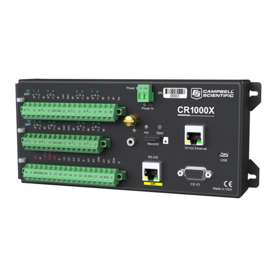
1.1 The CR1000X Datalogger The CR1000X is used in a broad range of measurement and control projects. Rugged enough for extreme conditions and reliable enough for remote environments, it plays a critical role in numerous complex applications. Used in applications all over the world, it is a powerful core component for your data acquisition system. -
Page 19: Programs
A program directs the datalogger on how and when sensors are measured, calculations are made, data is stored, and devices are controlled. The application program for the CR1000X is written in CRBasic, a programming language that includes measurement, data processing, and analysis routines, as well as the standard BASIC instruction set. - Page 20 Smart sensors SDI-12 RS-232 Modbus DNP3 TCP/IP RS-485 1. Data acquisition system components...
-
Page 21: Wiring Panel And Terminal Functions
2. Wiring panel and terminal functions The CR1000X wiring panel provides ports and removable terminals for connecting sensors, power, and communications devices. It is protected against surge, over-voltage, over-current, and reverse power. The wiring panel is the interface to most datalogger functions so studying it is a good way to get acquainted with the datalogger. - Page 22 Table 2-1: Analogue input terminal functions 1 2 3 4 5 6 7 8 9 10 11 12 13 14 15 16 VX1- RG1 RG2 DIFF ┌ ┐ ┌ ┐ ┌ ┐ ┌ ┐ ┌ ┐ ┌ ┐ ┌ ┐ ┌ ┐ H L H L H L H L H L H L H L H L Single-Ended...
- Page 23 Table 2-4: Voltage Output C1-C8 VX1-VX4 SW12-1 SW12-2 ü ü ü 5 Vdc ü ü 3.3 Vdc ü ü ü 12 Vdc C terminals have limited drive capacity. Voltage levels are configured in pairs. Table 2-5: Communications terminal functions C8 RS-232/CPI ü...
-
Page 24: Power Input
Troubleshooting power supplies (p. 120) The CR1000X can receive power via the POWER IN port as well as 5 Vdc via a USB connection. If both POWER IN and USB are connected, power will be supplied by whichever has the highest voltage. If USB is the only power source, then the CS I/O port and the 12V, SW12, and 5V terminals will not be operational. -
Page 25: Powering A Datalogger With A Vehicle
(often called batt_volt in the Public table) reference the external battery voltage. For information about the internal battery, see Internal battery (p. 105). 2.1.1 Powering a datalogger with a vehicle If a datalogger is powered by a motor-vehicle power supply, a second power supply may be needed. -
Page 26: Grounds
12 Vdc during measurement. Voltage on a SW12 terminal will change with datalogger supply voltage. CRBasic instruction SW12() controls the SW12 terminal. CS I/O port: used to communicate with and often supply power to Campbell Scientific peripheral devices. CAUTION: Voltage levels at the 12V and switched SW12 terminals, and pin 8 on the CS I/O port, are tied closely to the voltage levels of the main power supply. - Page 27 A good earth (chassis) ground will minimize damage to the datalogger and sensors by providing a low-resistance path around the system to a point of low potential. Campbell Scientific recommends that all dataloggers be earth grounded. All components of the system (dataloggers, sensors, external power supplies, mounts, housings) should be referenced to one common earth ground.
-
Page 28: Communications Ports
Smart sensors Modbus and DNP3 networks Ethernet Modems Campbell Scientific PakBus® networks Other Campbell Scientific dataloggers Campbell Scientific datalogger communications ports include: CS I/O RS-232/CPI Ethernet C terminals 2.4.1 USB port One USB port supports communicating with a computer through datalogger support software or through virtual Ethernet (RNDIS), and provides 5 Vdc power to the datalogger (powering through the USB port has limitations - details are available in the specifications). -
Page 29: Ports
(p. 81). 2.4.3.3 SDM port SDM is a protocol proprietary to Campbell Scientific that supports several Campbell Scientific digital sensor and communications input and output expansion peripherals and select smart sensors. It uses a common bus and addresses each node. CRBasic SDM device and sensor instructions configure terminals C1, C2, and C3 together to create an SDM port. -
Page 30: Rs-232/Cpi Port
CDM peripheral devices. It consists of a physical layer definition and a data protocol. CDM devices are similar to Campbell Scientific SDM devices in concept, but the CPI bus enables higher data-throughput rates and use of longer cables. CDM devices require more power to operate in general than do SDM devices. - Page 31 instructions. Other functions include device-driven interrupts, asynchronous communications and SDI-12 communications. The high voltage for these terminals defaults PortPairConfig() to 5 V, but it can be changed to 3.3 V using the instruction. Terminals C4, C5, and C7 can also be configured for pulse width modulation with a maximum period of 36.4 s.
-
Page 32: Setting Up The Data Logger
3. Setting up the data logger The basic steps for setting up your data logger to take measurements and store data are included in the following sections: Setting up communications with the data logger (p. 16) Virtual Ethernet over USB (RNDIS) (p. -
Page 33: Usb Or Rs-232 Communications
4. If prompted, select the Direct Connect connection type and click Next. 5. If this is the first time connecting this computer to a CR1000X via USB, click Install USB Driver, select your data logger, click Install, and follow the prompts to install the USB drivers. -
Page 34: Virtual Ethernet Over Usb (Rndis)
10. Set an Extra Response Time if you have a difficult or marginal connection and you want the data logger support software to wait a certain amount of time before returning a communication failure error. 11. LoggerNet and PC400 users can set a Max Time On-Line to limit the amount of time the data logger remains connected. -
Page 35: Ethernet Communications Option
(p. 103). 3.1.4 Ethernet communications option The CR1000X offers a 10/100 Ethernet connection. Use Device Configuration Utility to enter the data logger IP Address, Subnet Mask, and IP Gateway address. After this, use the EZSetup Wizard to set up communications with the data logger. If you already have the data logger IP information, you can skip these steps and go directly to... -
Page 36: Ethernet Leds
9. The Ethernet Power setting allows you to reduce the power consumption of the data logger. If there is no Ethernet connection, the data logger will turn off its Ethernet interface for the time specified before turning it back on to check for a connection. Select Always On, 1 Minute, or Disable. - Page 37 PC200W does not support IP connections. 2. Click Next. 3. Select the CR1000X Series from the list, enter a name for your station (for example, a site or project name), Next. 4. Select the IP Port connection type and click Next.
-
Page 38: Testing Communications And Connecting
3.2 Testing communications and connecting 3.2.1 Completing EZSetup 1. Using data logger support software EZ Setup, access the Communication Test window. This window is accessed during EZ Setup (see USB or RS-232 communications (p. 17) for more information). Alternatively, you can double-click a data logger from the station list to open the EZ Setup Wizard and access the Communication Test step from the left side of the window. -
Page 39: Making The Software Connection
Use the Time Zone Offset to specify a positive or negative offset to apply to the computer time when setting the data logger clock. This offset will allow you to set the clock for a data logger that needs to be set to a different time zone than the time zone of the computer (or to accommodate for changes in daylight saving time). -
Page 40: Creating A Program In Short Cut
Use the Short Cut software to generate a program for your data logger. Short Cut is included with your data logger support software. This section will guide you through programming a CR1000X data logger to measure the voltage of the data logger power supply, the internal temperature of the data logger, and a thermocouple. - Page 41 5. Use the Search feature or expand folders to locate your sensor or device. Double-click on a sensor or measurement in the Available Sensors and Devices list to configure the device (if needed) and add it to the Selected list. For the example program, expand the Sensors/Temperature folder and double-click Type T Thermocouple.
-
Page 42: Sending A Program To The Data Logger
16. Click Finish and give the program a meaningful name such as a site identifier. Click Save. 17. If LoggerNet or other data logger support software is running on your computer, and the data logger is connected to the computer (see Making the software connection (p. - Page 43 2. Using your data logger support software, click Send New... or Send Program (located in the Current Program section on the right side of the window). 3. Navigate to the program, select it, and click Open. For example: navigate to C:\Campbellsci\SCWin and select MyTemperature.cr1x.
-
Page 44: Data
4. Data 4.1 Default data tables By default, the data logger includes three tables: Public, Status, and DataTableInfo. Each of these tables only contains the most recent measurements and information. The Public table is configured by the data logger program, and updated at the scan interval set within the data logger program, It shows measurement and calculation results as they are made. -
Page 45: Collecting Data
LoggerNet users, select the Main category and Connect on the LoggerNet toolbar, select the data logger from the Stations list, then click Connect . Once connected, select a table to view using the Table Monitor. 4.2 Collecting data The data logger writes to data tables based on intervals and conditions set in the CRBasic program (see Creating data tables in a program (p. -
Page 46: Viewing Historic Data
option. All data from datalogger (Overwrite data files): Collects all of the data in the selected tables and replaces the existing data files on the computer. 4. By default, all output tables set up in the data logger program are selected for collection. 5. -
Page 47: Variables
+/–1.8 *10^–38 to 24 bits internal calculations, IEEE4 floating point +/–1.7 *10^38 (about 7 digits) output Campbell Scientific 13 bits –7999 to +7999 output two byte floating point (about 4 digits 4.4.1 Variables In CRBasic, the declaration of variables (via the... -
Page 48: Data Storage
While (IEEE 4 byte floating point) is used for variables and internal calculations, adequate for most stored data. Campbell Scientific 2 byte floating point (FP2)provides 3 or 4 IEEE4 significant digits of resolution, and requires half the memory space as (2 bytes per value vs 4). -
Page 49: About Data Tables
You can retrieve data based on a schedule or by manually choosing to collect data using datalogger support software (see Collecting data (p. 29)). Table 4-4: Example data TOA5, MyStation, CR1000X, 1142, CR1000X.Std.01, CPU:MyTemperature.CR1X, 1958, OneMin TIMESTAMP RECORD BattV_Avg PTemp_C_Avg Temp_C_Avg... -
Page 50: Header Rows
Table 4-4: Example data TOA5, MyStation, CR1000X, 1142, CR1000X.Std.01, CPU:MyTemperature.CR1X, 1958, OneMin TIMESTAMP RECORD BattV_Avg PTemp_C_Avg Temp_C_Avg Volts Deg C Deg C 2016-03-08 14:28:00 13.64 21.85 20.52 2016-03-08 14:29:00 13.65 21.85 20.64 4.5.1 Table definitions Each data table is associated with descriptive information, referred to as a“table definition,” that becomes part of the file header (first few lines of the file) when data is downloaded to a computer. - Page 51 abbreviation of the data process that outputs the data to storage. A list of these abbreviations follows in Data processing abbreviations (p. 35). If a field is an element of an array, the field name will be followed by a indices within parentheses that identify the element in the array.
-
Page 52: Data Records
Table 4-5: Data processing abbreviations Data processing name Abbreviation WindVector Median ETsz Solar Radiation (from ET) Time of Max Time of Min 4.5.1.2 Data records Subsequent rows are called data records. They include observed data and associated record keeping. The first field is a time stamp (TS), and the second field is the record number (RN). The time stamp shown represents the time at the beginning of the scan in which the data is written. - Page 53 the memory so the tables “fill up” (newest data starts to overwrite the oldest data) at about the same time. It is recommended you reserve the use of auto-allocation for data tables that store DataInterval() data based only on time (tables that store data based on the instruction).
-
Page 54: Data Memory
5. Data memory The datalogger includes three types of memory: SRAM, Flash, and Serial Flash. A memory card slot is also available for an optional microSD card. Note that the datalogger USB port does not support USB flash or thumb drives (see Communications ports (p. -
Page 55: Flash Memory
is available for user-allocated data tables. This memory is given lowest priority in SRAM memory allocation. Communication Memory 1: Memory used for construction and temporary storage of PakBus packets. Communication Memory 2: Memory used to store the list of known nodes and routes to nodes. -
Page 56: Usr Drive
Data concerning the datalogger memory are posted in the Status and DataTableInfo tables. For additional information on these tables, see Information tables and settings (advanced) (p. 124). For additional information on datalogger memory, visit the Campbell Scientific blog article, "How to Know when Your Datalogger Memory is Getting Full." 5.4.2 USR drive Battery-backed SRAM can be partitioned to create a FAT USR drive, analogous to partitioning a second drive on a computer hard disk. -
Page 57: Cpu Drive
Campbell Scientific. These cards are industrial-grade and have passed Campbell Scientific hardware testing. Use of consumer grade cards substantially increases the risk of data loss. Following are listed advantages Campbell Scientific cards have over less expensive commercial-grade cards: Less susceptible to failure and data loss. -
Page 58: Formatting Microsd Cards
inadequate, the datalogger will warn that the card is not being used. However, the CRBasic program runs anyway and data is stored to SRAM. When a card is inserted later, data accumulated in the SRAM table is copied to the card. A microSD card can also facilitate the use of powerup.ini (see File management via powerup.ini (p. -
Page 59: File Management Via Powerup.ini
Dim/flashing orange: Card has been removed and has been out long enough that CPU memory has wrapped and data is being overwritten without being stored to the card. 5.6 File management via powerup.ini Another way to upload a program, install a datalogger OS, or format a drive is to create a powerup.ini file. -
Page 60: Example Powerup.ini Files
datalogger, connect to it in Device Configuration Utility, click the Backup menu and select Backup Datalogger. Table 5-1: Powerup.ini commands Command Action Details Copies a program file to a drive and sets the program to both Run always, Run Now and Run on Power Up. Data on a memory card from preserve data the previously running program will be preserved if table structures have not changed. - Page 61 5,,usr: Example: Send OS on Power Up 'Load an operating system (.obj) file into FLASH as the new OS 9,CR1000X.Std.01.obj Example: Run Program from SC115 Flash Memory Drive 'A program file is carried on an SC115 Flash Memory drive. 'Do not copy program file from SC115 'Run program always, erase data.
-
Page 62: Measurements
6. Measurements 6.1 Voltage measurements 6.2 Current-loop measurements 6.3 Resistance measurements 6.4 Thermocouple Measurements 6.5 Period-averaging measurements 6.6 Pulse measurements 6.7 Vibrating wire measurements 6.8 Sequential and pipeline processing modes 6.1 Voltage measurements Voltage measurements are made using an ADC. A high-impedance programmable-gain amplifier amplifies the signal. -
Page 63: Single-Ended Measurements
WARNING: Sustained voltages in excess of ±20 V applied to terminals configured for analogue input will damage CR1000X circuitry. 6.1.1 Single-ended measurements A single-ended measurement measures the difference in voltage between the terminal configured for single-ended input and the reference ground. For example, single-ended channel 1 is comprised of terminals SE 1 and . -
Page 64: Reverse Differential
BrHalf4W() TCDiff() 6.1.2.1 Reverse differential Differential measurements have the advantage of an input reversal option, RevDiff. When RevDiff is set to True, two differential measurements are made, the first with a positive polarity and the second reversed. Subtraction of opposite polarity measurements cancels some offset voltages associated with the measurement. -
Page 65: Minimizing Ground Potential Differences
Rapid sampling is required. Single-ended measurement time is about half that of differential measurement time. Sensor is not designed for differential measurements. Some Campbell Scientific sensors are not designed for differential measurement, but the drawbacks of a single-ended measurement are usually mitigated by large programmed excitation and/or sensor output voltages. -
Page 66: Ground Potential Differences
help. Problem wires can also be tied directly to the ground lug to minimize induced single-ended offset voltages. Ground potential differences Because a single-ended measurement is referenced to datalogger ground, any difference in ground potential between the sensor and the datalogger will result in a measurement error. Differential measurements MUST be used when the input ground is known to be at a different ground potential from datalogger ground. -
Page 67: Minimizing Power-Related Artifacts
If the open circuit is at the end of a very long cable, the test pulse may not charge the cable (with its high capacitance) up to a voltage that generates NAN or a distinct error voltage. The cable may even act as an aerial and inject noise which also might not read as an error voltage. -
Page 68: Minimizing Electronic Noise
Minimizing electronic noise Electronic noise can cause significant error in a voltage measurement, especially when measuring voltages less than 200 mV. So long as input limitations are observed, the PGIA ignores voltages, including noise, that are common to each side of a differential-input pair. This is the common- mode voltage. -
Page 69: Filtering To Reduce Measurement Noise
Preventing and Attacking Measurement Noise Problems. CR1000X filtering details The datalogger utilizes a sigma-delta ADC that outputs digitized data at a rate of 31250 samples per second. User-specified filtering is achieved by averaging several samples from the ADC. -
Page 70: Minimizing Settling Errors
Measuring settling time Settling time for a particular sensor and cable can be measured with the CR1000X. Programming a series of measurements with increasing settling times will yield data that indicate at what settling time a further increase results in negligible change in the measured voltage. The programmed settling time at this point indicates the settling time needed for the sensor / cable combination. - Page 71 CRBasic Example 1: Measuring Settling Time DataTable (Settle,True,100) Sample (20,PT(),IEEE4) EndTable BeginProg Scan (1,Sec,3,0) BrFull (PT(1), 1,mV200,1,Vx1,1,2500,True,True, 100,15000,1.0,0) BrFull (PT(2), 1,mV200,1,Vx1,1,2500,True,True, 200,15000,1.0,0) BrFull (PT(3), 1,mV200,1,Vx1,1,2500,True,True, 300,15000,1.0,0) BrFull (PT(4), 1,mV200,1,Vx1,1,2500,True,True, 400,15000,1.0,0) BrFull (PT(5), 1,mV200,1,Vx1,1,2500,True,True, 500,15000,1.0,0) BrFull (PT(6), 1,mV200,1,Vx1,1,2500,True,True, 600,15000,1.0,0) BrFull (PT(7), 1,mV200,1,Vx1,1,2500,True,True, 700,15000,1.0,0) BrFull (PT(8), 1,mV200,1,Vx1,1,2500,True,True, 800,15000,1.0,0) BrFull...
-
Page 72: Factors Affecting Accuracy
(right axis). The reading has settled to 99.5% of the final value by the fourteenth measurement, which is contained in variable PT(14). This is suitable accuracy for the application, so a settling time of 1400 µs is determined to be adequate. 6.1.3.7 Factors affecting accuracy Accuracy describes the difference between a measurement and the true value. -
Page 73: Measurement Accuracy Example
Measurement accuracy example The following example illustrates the effect percent-of-reading and offset have on measurement accuracy. The effect of offset is usually negligible on large signals. Example: Sensor-signal voltage: approximately 1050 mV CRBasic measurement instruction: VoltDiff() Programmed input-voltage range (Range) : mV 500 0 (±5000 mV) Input measurement reversal (RevDiff): True Datalogger circuitry temperature: 10°... - Page 74 Using MeasOff = True for better offset compensation. Using excitation reversal (RevEx = True) with bridge measurements. Programming longer settling times. Single-ended measurements are susceptible to voltage drop at the ground terminal caused by return currents from another device that is powered from the datalogger wiring panel, such as another manufacturer's communications modem, or a sensor that requires a lot of power.
-
Page 75: Compensating For Offset Voltage
The following table lists some of the tools available to minimize the effects of offset voltages: Table 6-2: Offset voltage compensation options Measure Offset During Measure Offset CRBasic Excitation Background Calibration Input Reversal During Measurement Reversal (RevDiff=False) (RevDiff=True) Measurement Instruction (RevEx=True) (RevEx=False) (MeasOff=True) -
Page 76: Measuring Ground Reference Offset Voltage
Ratiometric differential measurement instructions allow both RevDiff and RevEx to be set True. This results in four measurement sequences, which the datalogger processes into the reported measurement: positive excitation polarity with positive differential input polarity negative excitation polarity with positive differential input polarity positive excitation polarity with negative differential input polarity negative excitation polarity with negative differential input polarity For ratiometric single-ended measurements, such as a BrHalf(), setting RevEx = True... -
Page 77: Current-Loop Measurements
measurement accuracy. When MeasOff = True, a measurement of the single-ended offset VoltSE() TCSe() instruction. When MeasOff = voltage is made at the beginning of the False, measurements will be corrected for the offset voltage determined during self-calibration. For installations experiencing fluctuating offset voltages, choosing MeasOff = True for the VoltSE() TCSe() instruction results in better offset voltage performance. -
Page 78: Example Current-Loop Measurement Connections
6.2.1 Example Current-Loop Measurement Connections The following table shows example schematics for connecting typical current sensors and devices. See also Current-loop measurement specifications (p. 169). Sensor Type Connection Example 2-wire transmitter using datalogger power 2-wire transmitter using external power 3-wire transmitter using datalogger power 3-wire transmitter using external power 6. -
Page 79: Resistance Measurements
Sensor Type Connection Example 4-wire transmitter using datalogger power 4-wire transmitter using external power 6.3 Resistance measurements Bridge resistance is determined by measuring the difference between a known voltage applied to the excitation (input) of a resistor bridge and the voltage measured on the output arm. The datalogger supplies a precise voltage excitation via VX terminals. - Page 80 Resistive-Bridge Type and CRBasic Instruction and Relational Formulas Circuit Diagram Fundamental Relationship Half Bridge CRBasic Instruction: BrHalf() Fundamental Relationship: Three Wire Half Bridge CRBasic Instruction: BrHalf3W() Fundamental Relationship: Four Wire Half Bridge CRBasic Instruction: BrHalf4W() Fundamental Relationship: 6. Measurements...
- Page 81 = sensor return voltages; R = fixed, bridge or completion resistor; R variable or sensing resistor. Campbell Scientific offers terminal input modules to facilitate this measurement. Offset voltage compensation applies to bridge measurements. In addition to RevDiff and MeasOff parameters discussed in Minimizing offset voltages (p.
-
Page 82: Strain Measurements
when excitation is reversed, the differential measurement of the voltage drop across the sensor is made with excitation at both polarities and then excitation is again applied and reversed for the measurement of the voltage drop across the fixed resistor. The results of the measurements (X) must then be processed further to obtain the resistance value, which requires additional program execution time. - Page 83 dashed code when the bridge is configured so the output increases with increasing strain. A dashed code sets the polarity of V to negative. Table 6-3: StrainCalc() configuration codes BrConfig Code Configuration Quarter-bridge strain gage Half-bridge strain gauge . One gauge parallel to strain, the other at 90°...
-
Page 84: Ac Excitation
Table 6-3: StrainCalc() configuration codes BrConfig Code Configuration Full-bridge strain gauge. Half the bridge has two gauges parallel to +ɛ and -ɛ, and the other half to +νɛ and -νɛ 1: Full-bridge strain gauge. Half the bridge has two gauges parallel to +ɛ... -
Page 85: Accuracy For Resistance Measurements
Voltage Measurement Accuracy, Self- Calibration, and Ratiometric Measurements NOTE: Error discussed in this section and error-related specifications of the CR1000X do not include error introduced by the sensor, or by the transmission of the sensor signal to the datalogger. For accuracy specifications of ratiometric resistance measurements, see... -
Page 86: Period-Averaging Measurements
voltage measurement device, such as the datalogger. These connections form the reference junction. If the two junctions (measurement and reference) are at different temperatures, a voltage proportional to the difference is induced in the wires. This phenomenon is known as the Seebeck effect. -
Page 87: Pulse Measurements
internal comparator without the need for additional input conditioning circuitry. The threshold allows direct connection of standard digital signals, but it is not recommended for small- amplitude sensor signals. A threshold other than zero results in offset voltage drift, limited accuracy (approximately ±10 mV) and limited resolution (approximately 1.2 mV). - Page 88 The datalogger includes terminals that are configurable for pulse input to measure counts or frequency as shown in the following image. Table 6-4: Pulse input terminals and the input types they can measure Input Type Pulse Input Terminal Data Option High-frequency C (all) Counts...
-
Page 89: Low-Level Ac Measurements
CRBasic instruction: Low-level ac signals cannot be measured directly by C terminals. Peripheral terminal expansion modules, such as the Campbell Scientific LLAC4, are available for converting low-level ac signals to square-wave signals measurable by C terminals. For more information, see Pulse measurement specifications (p. -
Page 90: P Terminals
6.6.2.1 P terminals CRBasic instruction: PulseCount() High-frequency pulse inputs are routed to an inverting CMOS input buffer with input hysteresis. Pulse measurement specifications (p. 169) for more information. 6.6.2.2 C terminals PulseCount() CRBasic instructions: 6.6.3 Switch-closure and open-collector measurements Switch-closure and open-collector (also called current-sinking) signals can be measured on P or C terminals. -
Page 91: C Terminals
Switch Closure on P Terminal Open Collector on P Terminal 6.6.3.2 C terminals Switch-closure mode is a special case edge-count function that measures dry-contact switch- closures or open collectors. The operating system filters bounces. PulseCount() CRBasic instruction: See also Pulse measurement specifications (p. -
Page 92: Quadrature Measurements
For more information, see: Pulse measurement specifications (p. 169) Digital input/output specifications (p. 171) Period-averaging measurement specifications (p. 168) 6.6.5 Quadrature measurements The Quadrature() instruction is used to measure shaft or rotary encoders. A shaft encoder outputs a signal to represent the angular position or motion of the shaft. Each encoder will have two output signals, an A line and a B line. -
Page 93: Pulse Measurement Tips
Counting the increase at each rising and falling edge of both channels when channel A leads channel B. Counting the decrease at each rising and falling edge of both channels when channel B leads channel A. For more information, see Pulse measurement specifications (p. -
Page 94: Vibrating Wire Measurements
6.7.1 VSPECT® Measuring the resonant frequency by means of period averaging is the classic technique, but Campbell Scientific has developed static and dynamic spectral-analysis techniques (VSPECT) that produce superior noise rejection, higher resolution, diagnostic data, and, in the case of dynamic VSPECT, measurements up to 333.3 Hz. -
Page 95: Sequential Mode
The exact time at which measurements are made in sequential mode may vary if other measurements or processing are made conditionally, if there is heavy communications activity, or if other interrupts occur (such as accessing a Campbell Scientific memory card). 6.8.2 Pipeline mode Pipeline mode handles measurement, most digital, and processing tasks separately, and, in many cases, simultaneously. -
Page 96: Slow Sequences
6.8.3 Slow Sequences Priority of a slow sequence (SlowSequence)in the datalogger will vary, depending upon whether the datalogger is executing its program in pipeline mode or sequential mode. With the important exception of measurements, when running in pipeline mode all sequences in the program have the same priority. -
Page 97: Communications Protocols
Dataloggers communicate with datalogger support software, other Campbell Scientific dataloggers, and other hardware and software using a number of protocols including PakBus, Modbus, DNP3, CPI, SPI, and TCP/IP. Several industry-specific protocols are also supported. CAN-bus is supported when using the Campbell Scientific SDM-CAN communications module.See also Communications specifications (p. -
Page 98: General Serial Communications
Refer to the manual of the sensor or device to find its protocol and then select the appropriate options for each CRBasic parameter. See the application note Interfacing Serial Sensors with Campbell Scientific Dataloggers for more programming details and examples. -
Page 99: About Modbus
Why Modbus Matters: An Introduction How to Access Live Measurement Data Using Modbus Using Campbell Scientific Dataloggers as Modbus Slave Devices in a SCADA Network Because Modbus has a set command structure, programming the datalogger to get data from field instruments can be much simpler than from some other serial sensors. Because Modbus uses a common bus and addresses each node, field instruments are effectively multiplexed to a datalogger without additional hardware. -
Page 100: Modbus Protocols
Not only can intelligent devices such as microcontrollers and programmable logic controllers (PLCs) communicate using Modbus, but many intelligent sensors have a Modbus interface that enables them to send their data to host systems. Examples of using Modbus with Campbell Scientific dataloggers include: Interfacing dataloggers and Modbus-enabled sensors. -
Page 101: Understanding Modbus Terminology
Devices labelled as Modbus gateways will convert from Modbus TCP to Modbus RTU. Campbell Scientific dataloggers support Modbus RTU, Modbus ASCII, and Modbus TCP protocols. If the connection is over IP, Campbell Scientific dataloggers always use Modbus TCP. Modbus slave functionality over other comports use RTU. When acting as a master, the... -
Page 102: Modbus Master-Slave Protocol
Campbell Scientific dataloggers can be programmed to be a Modbus master or Modbus slave - or even both at the same time! This proves particularly helpful when your datalogger is a part of two wider area networks. -
Page 103: Endianness
Little-endian format reverses this order: the sequence stores the least significant byte first and the most significant byte last. Endinness is used in some Modbus programming so it is important to note that the CR1000X is a big-endian instrument. 7.2.6.2 Function codes A function code tells the slave which storage entity to access and whether to read from or write to that entity. -
Page 104: Modbus Information Storage
In a 16-bit memory location, a 4-byte value takes up two registers. The Modbus protocol always refers to data registers with a starting address number, and a length to indicate how many registers to transfer. Campbell Scientific uses 1-based numbering (a common convention for numbering registers in ModbusMaster() equipment) in the instruction. -
Page 105: Data Types
ModbusOption to avoid post-processing. Signed 32-bit integer Signed 32-bit integers require two registers per value. This data type corresponds to the native Long variable type in Campbell dataloggers. Declare your variables as type Long before using 7. Communications Protocols... -
Page 106: Unsigned 32-Bit Integer
Long holding it. 32-Bit floating point 32-bit floating point values use 2 registers each. This is the default FLOAT data type in Campbell Scientific dataloggers . Select the appropriate ModbusOption to avoid post-processing. -
Page 107: Result Code -02: Illegal Data Address
An uncommon cause for the -01 result is a device with an incomplete implementation of Modbus. Some devices do not fully implement parsing Modbus commands. Instead, they are hardcoded to respond to certain Modbus messages. The result is that the device will report an error when you try selectively polling registers. -
Page 108: Ip Address
Settings Editor: Ethernet | {information box} to see the assigned IP address. The CR1000X provides a DNS client that can query a DNS server to determine if an IP address has been mapped to a hostname. If it has, then the hostname can be used interchangeably with the IP address in some datalogger instructions. -
Page 109: Serial Peripheral Interface (Spi) And I2C
For additional information on I2C, see www.i2c-bus.org. 7.6 PakBus communications PakBus is a Campbell Scientific communications protocol. By using signed data packets, PakBus increases the number of communication and networking options available to the datalogger. The datalogger allows PakBus communications on all available communications ports. For... -
Page 110: Communications
In a PakBus network, each datalogger is assigned a unique address. The default PakBus address in most devices is 1. To communicate with the datalogger, the datalogger support software must know the datalogger PakBus address. The PakBus address is changed using Device Configuration Utility, datalogger Settings Editor, or PakBus Graph software. -
Page 111: Transparent Mode Commands
To enter the SDI-12 transparent mode, enter the datalogger support software terminal emulator: 1. Press Enter until the datalogger responds with the prompt CR1000X>. 2. Type SDI12 at the prompt and press Enter. 3. In response, the query Enter Cx Port is presented with a list of available ports. Enter the port number assigned to the terminal to which the SDI-12 sensor is connected, and press Enter. -
Page 112: Programmed Mode/Recorder Mode
SDI12SensorSetup() SDI12SensorResponse() instruction pair programs the datalogger to behave as an SDI-12 sensor. A common use of this feature is to copy data from the datalogger to other Campbell Scientific dataloggers over a single data-wire interface (terminal 7. Communications Protocols... -
Page 113: Power Considerations
configured for SDI-12 to terminal configured for SDI-12), or to copy data to a third-party SDI-12 recorder. SDI12SensorSetup() SDI12SensorResponse() Details of using the instruction pair can be found in the CRBasic Editor help. When programmed as an SDI-12 sensor, the datalogger will respond to SDI-12 commands M, MC, C, CC, R, RC, V, ?, and I. - Page 114 Table 7-1: Example power use for a network of SDI-12 probes Time into Time Probe Probe Probe Probe Total Measurement Command Probes 1 (mA) 2 (mA) 3 (mA) 4 (mA) (mA) Processes Awake Expires Sleep 0.25 0.25 0.25 0.25 2–14 1D0! 17-29 Sleep...
-
Page 115: Maintaining Your Datalogger
Desiccant should be changed periodically. If sending the datalogger to Campbell Scientific for calibration or repair, consult first with Campbell Scientific. If the datalogger is malfunctioning, be prepared to perform some... -
Page 116: About Background Calibration
About background calibration (p. 100). You can download and print calibration certificates for many products you have purchased by logging in to the Campbell Scientific website and going to: https://www.campbellsci.com/calcerts. NOTE: Note, you will need your product's serial number to access its certificate. - Page 117 Networks that are accessible to many individuals Some options to secure your datalogger from mistakes or tampering include: Sending the latest operating system to the datalogger. See Updating the operating system (p. 109) for more information. Disabling unused services and securing those that are used. This includes disabling HTTP, HTTPS, FTP, Telnet, and Ping network services (Device Configuration Utility >...
-
Page 118: Security Codes
8.2.1 Security codes The datalogger employs a security scheme that includes three levels of security. Security codes can effectively lock out innocent tinkering and discourage wannabe hackers on all communication links. However, any serious hacker with physical access to the datalogger or to the communications hardware can, with only minimal trouble, overcome the five-digit security codes. -
Page 119: Creating A .Csipasswd File
How to Use Datalogger Security Codes How Can Data be Made More Secure on a CRBasic PakBus Datalogger 8.2.2 Creating a .csipasswd file The datalogger employs a security code scheme that includes three levels of security (see Datalogger security (p. 100) for more information). This scheme can be used to limit access to a datalogger that is publicly available. -
Page 120: Command Syntax
Do not completely seal the enclosure if lead-acid batteries are present; hydrogen gas generated by the batteries may build to an explosive concentration. The following details a typical installation using a Campbell Scientific enclosure. The datalogger has mounting holes through which small screws are inserted into nylon anchors in the backplate. -
Page 121: Internal Battery
Time. Clock will need resetting when the battery is replaced. Final-memory data tables. A replacement lithium battery can be purchased from Campbell Scientific or another supplier. AA, 2.4 Ah, 3.6 Vdc (Tadiran TL 5903/S) for battery-backed SRAM and clock. 3-year life with no external power source. -
Page 122: Replacing The Internal Battery
WARNING: Misuse or improper installation of the internal lithium battery can cause severe injury. Fire, explosion, and severe burns can result. Do not recharge, disassemble, heat above 100 °C (212 °F), solder directly to the cell, incinerate, or expose contents to water. Dispose of spent lithium batteries properly. -
Page 123: Electrostatic Discharge And Lightning Protection
While elaborate, expensive, and nearly infallible lightning protection systems are on the market, Campbell Scientific, for many years, has employed a simple and inexpensive design that protects most systems in most circumstances. The system consists of a lightning rod, metal mast, heavy-gauge ground wire, and ground rod to direct damaging current away from the 8. -
Page 124: Power Budgeting
datalogger. This system, however, is not infallible. The following image displays a typical application of the system: All critical inputs and outputs on the datalogger are ESD protected to 75 V. To be effective, the earth ground lug must be properly connected to earth (chassis) ground. Communications ports are another path for transients. -
Page 125: Updating The Operating System
Power output specifications (p. 164) 8.7 Updating the operating system Campbell Scientific posts operating system (OS) updates at www.campbellsci.eu/downloads when they become available. It is recommended that before deploying instruments, you check operating system versions and update them as needed. The datalogger operating system version is shown in the Status table, Station Status Summary, and Device Configuration Utility Deployment >... -
Page 126: Sending An Operating System To A Local Datalogger
8.7.1 Sending an operating system to a local datalogger Send an OS using Device Configuration Utility. This method requires a direct connection between your datalogger and computer. 1. Download the latest Operating System at www.campbellsci.eu/downloads. 2. Locate the .exe download and double-click to run the file. This will extract the .obj OS file to the C:\Campbellsci\Lib\OperatingSystems folder. - Page 127 PC200W and PC400 users, select the datalogger from the list and click Connect 4. Select File Control at the top of the Connect window. 5. Click Send at the top of the File Control window. 6. Navigate to the C:\Campbellsci\Lib\OperatingSystems folder. 7.
-
Page 128: Tips And Troubleshooting
9. Tips and troubleshooting Start with these basic procedures if a system is not operating properly. 1. Using a voltmeter, check the voltage of the primary power source at the POWER IN terminals on the face of the datalogger, it should be 10 to 18 Vdc. 2. -
Page 129: Checking Station Status
9.9 File system error codes 9.10 File name and resource errors 9.11 Background calibration errors 9.12 Information tables and settings (advanced) Also, consider checking, or posting your question to, the Campbell Scientific user forum http:// www.campbellsci.com/forum. Our web site https://www.campbellsci.eu... -
Page 130: Results For Last Program Compiled
Check your datalogger operating system version; recent operating system versions have improved stability of IP communications. If any of these are not the apparent cause, contact Campbell Scientific for assistance (see https://www.campbellsci.eu/support). Causes that may require assistance include:... -
Page 131: Variable Out Of Bounds
9.1.6 Variable out of bounds Variable-out-of-bounds errors happen when an array is not sized to the demands of the program. The datalogger attempts to catch out-of-bounds errors at compile time. However, it is not always possible; so, these errors may occur during runtime. Variable-out-of-bounds errors are always caused by programming problems. -
Page 132: Timekeeping
NOTE: There is no such thing as NAN for integers. Values that are converted from float to integer will be expressed in data tables as the most negative number for a given data type. For example, the most negative number of data type FP2 is –7999; so, NAN for FP2 data will appear in a data table as –7999. -
Page 133: Avoiding Time Skew
a measurement is taken depends on several factors. The time stamp in common CRBasic programs matches the time at the beginning of the current scan as measured by the real-time datalogger clock. If a scan starts at 15:00:00, data output during that scan will have a time stamp of 15:00:00 regardless of the length of the scan, or when in the scan a measurement is made. -
Page 134: Program Does Not Compile
9.4.1 Program does not compile When a program is compiled, the CRBasic Editor checks the program for syntax errors and other inconsistencies. The results of the check are displayed in a message window at the bottom of the main window. If an error can be traced to a specific line in the program, the line number will be listed before the error. -
Page 135: Processor Reset
When a program compiles, all variables are initialized. A program is recompiled after a power failure or a manual stop. For instances that require variables to be preserved through a program PreserveVariables() PreserveOneVariable() recompile, the CR1000X has the instructions. 9.5.3 Manual data table reset Data table memory is selectively reset from: Datalogger support software: Station Status >... -
Page 136: Formatting Drives
Ensure correct polarity of the connection. If the datalogger powers up and works, troubleshoot the datalogger power supply. When diagnosing or adjusting power equipment supplied by Campbell Scientific, it is recommended you consider: Battery-voltage test... -
Page 137: Minimizing Ground Loop Errors
Note that the geometry of the electrodes has a great effect on the magnitude of this error. The Delmhorst gypsum block used in the Campbell Scientific 227 probe has two concentric cylindrical 9. Tips and troubleshooting... -
Page 138: Field Calibration
Campbell Scientific resistive soil probes and conductivity probes are built with series capacitors to block this dc current. In addition to preventing sensor deterioration, the capacitors block any dc component from affecting the measurement. -
Page 139: File Name And Resource Errors
11 Filename too long or has bad chars 12 File in path is not a directory 13 Access permission, opening DIR or LABEL as file, or trying to open file as DIR or mkdir existing file 14 Opening read-only file for write 15 Disk full (can't allocate new cluster) 16 Root directory is full 17 Bad file ptr (pointer) or device not initialized... -
Page 140: Background Calibration Errors
Information tables and settings consist of fields, settings, and system information essential to setup, programming, and debugging of many advanced CR1000X systems. In many cases, the info tables and settings keyword can be used to pull that field into a running CRBasic program. -
Page 141: Information Tables Directories
Communications and processor bandwidth are consumed when generating the Status and other information tables. If datalogger is very tight on processing time, as may occur in very fast, long, or complex operations, retrieving these tables repeatedly may cause skipped scans. Settings that affect memory usage force the datalogger program to recompile, which may cause loss of data. -
Page 142: Communications
Action Keywords ProgErrors ProgSignature Programming Errors SkippedScan StartUpCode VarOutOfBound DataFillDays Data tables SkippedRecord MemoryFree Memory MemorySize Datalogger auto-resets WatchdogErrors OSDate Operating system OSSignature OSVersion Battery Power LithiumBattery Low12VCount 9.12.1.2 Communications For detailed information on communication protocols, see Communications Protocols (p. 81). General communications Baudrate RS232Handshaking... -
Page 143: Tcp_Ip Communications
TCP_IP communications CSIOnetEnable HTTPPort IPAddressCSIO EthernetPower IPAddressEth IPTraceComport FTPEnabled IPGateway PingEnabled FTPPassword IPGatewayCSIO TelnetEnabled FTPPort IPMaskCSIO UDPBroadcastFilter FTPUserName IPMaskEth HTTPEnabled IPTraceCode 9.12.1.3 Background calibration About background calibration (p. 100) for more information. ErrorCalib CalGain SkippedSystemScan LastSystemScan CalOffset SystemProcTime MaxSystemProcTime 9.12.1.4 Data DataFillDays DataTableName SkippedRecord... -
Page 144: Signatures
9.12.2 Information tables and settings descriptions Information tables and settings consist of fields, settings, and system information essential to setup, programming, and debugging of many advanced CR1000X systems. There are several locations where this system information and settings are stored or changed. -
Page 145: Status Table System Information And Settings
Keyword Information and Location Reports the names of data tables. Array elements are in the order the data tables are declared in the CRBasic program. DataTableName String data type Read only Record number is incremented when any one of the DataTableInfo fields change, for example SkippedRecord. - Page 146 Keyword Information and Location Voltage (Vdc) of the battery powering the system. Updates when viewing the Status table or via program code. Battery Numeric data type Read only Shows the current pipeline mode processing buffer depth, which indicates how far the processing task is currently behind the measurement task. Updated at the conclusion of scan processing, prior to waiting for the next BuffDepth scan.
- Page 147 See MaxSystemProcTime, SkippedSystemScan, and SystemProcTime. LastSystemScan Numeric data type Read only Voltage of the internal lithium battery. Updated at CR1000X power up. For battery information, see Internal battery (p. 105). LithiumBattery Numeric data type...
- Page 148 Keyword Information and Location Maximum time (μs) required to run through processing for the current scan. Value is reset when the scan exits. Enter 0 to reset. Updated at the MaxProcTime conclusion of scan processing, prior to waiting for the next scan. Numeric data type Maximum time (μs) required to process the auto (background) calibration, which runs in a hidden slow-sequence type scan.
- Page 149 Signature of the operating system. OSSignature Numeric data type Read only Version of the operating system in the CR1000X. Updated at OS startup. OSVersion String data type Read only Lists routes or router neighbours known to the datalogger at the time the setting was read.
- Page 150 Keyword Information and Location Provides information on the configuration settings (input, output, SDM, SDI-12, COM port) for C terminals in numeric order of terminals. Default = Input. Updates when the port configuration changes. PortConfig String data type Read only States of C terminals configured for control. On/high (True) or off/low (False).
- Page 151 Updates after compiling and before RunSignature running the program. Numeric data type Read only CR1000X serial number assigned by the factory when the datalogger was calibrated. Stored in flash memory. Updated at startup. SerialNumber Numeric data type Read only...
- Page 152 Keyword Information and Location Indicates how the running program was compiled. Updated at startup. 65 = Run on powerup is running and normal powerup occurred. StartUpCode Numeric data type Read only Station name stored in flash memory. This is not the same name as that is entered into your datalogger support software.
-
Page 153: Device Configuration Utility Settings
9.12.2.3 Device Configuration Utility settings Access settings, using Device Configuration Utility. Clicking on a setting in Device Configuration Utility also provides information about that setting. 9. Tips and troubleshooting... - Page 154 Keyword Information and Location This setting governs the baud rate that the datalogger will use for a given port in order to support serial communications. For some ports (COM), this setting also controls whether the port will be enabled for serial communications.
- Page 155 Keyword Information and Location This setting specifies a list of PakBus addresses for routers that are able to work as Central Routers. By specifying a non-empty list for this setting, the datalogger will be configured as a Branch Router meaning that it will not be required to keep track of neighbours of any routers except those in its own branch.
- Page 156 Keyword Information and Location Specifies the configuration for a datalogger control port as it relates to serial communications. It is significant only when the associated port baud rate setting is set to something other than Disabled. This setting denotes the physical layer properties used for communications. It does not indicate the port's current configuration as it relates to standard or inverted logic.
- Page 157 Keyword Information and Location Controls whether the CS I/O IP #1 or #2 TCP/IP interface should be enabled. Numeric data type CSIOxnetEnable Where to find: Settings Editor tab in Device Configuration Utility: CS I/O IP | Interface Enabled #1 or 2 Reports the IP address, network mask, and default gateway for each of the datalogger's active network interfaces.
- Page 158 Keyword Information and Location Controls the behavior of the datalogger when it restarts with a different program and it detects that data files created by the CardOut() are present but do not match the new program. If this value is set to one, the datalogger will delete these files so that new files can be stored.
- Page 159 Keyword Information and Location This setting specifies how the datalogger controls power to its Ethernet interface. This setting provides a means of reducing the datalogger power consumption while Ethernet is not connected. Always on, 1 Minute, or Disable. EthernetPower Where to find: Settings Editor tab in Device Configuration Utility: Ethernet | Ethernet Power This setting controls how the datalogger will handle incoming files with...
- Page 160 Keyword Information and Location Configures the TCP port on which the FTP service is offered. The default value is usually sufficient unless a different value needs to be specified to accommodate port mapping rules in a network address translation firewall. Default = 21. FTPPort Numeric data type Where to find:...
- Page 161 Keyword Information and Location Configures the TCP port on which the HTTP (web server) service is offered. Generally, the default value is sufficient unless a different value needs to be specified to accommodate port-mapping rules in a network-address translation firewall. Default = 80. HTTPPort Numeric data type Where to find:...
- Page 162 Keyword Information and Location This setting specifies the name of a file to be implicitly included at the end of the current CRBasic program or can be run as the default program. In order to work as an include file, the file referenced by this setting cannot contain a BeginProg() statement or define any variable names or tables that are defined in the main program file.
- Page 163 Keyword Information and Location Specifies the IP address for the internet interface connected via the peripheral port to devices such as the NL115 and NL120. If this value is specified as "0.0.0.0" (the default), the datalogger will use DHCP to configure the effective value for this setting as well as the Ethernet Default Gateway and Ethernet Subnet Mask settings.
- Page 164 Keyword Information and Location These settings specify the subnet masks for the CS I/O bridge mode internet interface. If the corresponding CS I/O Address setting is set to a value of "0.0.0.0", the datalogger will configure the effective value of this setting using DHCP.
- Page 165 Keyword Information and Location This setting controls whether the datalogger is configured as a router or as a leaf node. If the value of this setting is true, the datalogger will be configured to act as a PakBus router. That is, it will be able to forward PakBus packets from one port to another.
- Page 166 Keyword Information and Location This setting specifies, for a given port, the explicit list of PakBus node addresses that the datalogger will accept as neighbours. If the list is empty (the default value) any node will be accepted as a neighbour. This setting will not affect the acceptance of a neighbour if that neighbor's address is greater than 3999.
- Page 167 Keyword Information and Location This setting specifies text that will be used to generate the key for encrypting PakBus messages sent or received by this datalogger. If this value is specified as an empty string, the datalogger will not use PakBus encryption.
- Page 168 Keyword Information and Location By default, PakBus TCP communications are enabled. To disable PakBus TCP communications, set the PakBusPort setting to 65535. Numeric data type PakBusTCPEnabled Where to find: Settings Editor tab in Device Configuration Utility: Network Services | PakBus/TCP Service Port This setting specifies a password that, if not empty, will make the datalogger authenticate any incoming or outgoing PakBus/TCP connection.
- Page 169 Keyword Information and Location PCAP is a packet capture (PCAP) file of network packet data (network traffic) that can be opened by Wireshark. This setting specifies the network interface, file name, and maximum size of the PCAP file. For example: "usr:debug.pcap"...
- Page 170 Keyword Information and Location Specifies the dial string that would follow the ATD command (#777 for the Redwing CDMA). Alternatively, this value can specify a list of AT commands where each command is separated by a semi-colon (;). When specified in this fashion, the datalogger will transmit the string up to the semicolon, transmit a carriage return to the modem, and wait for two seconds before proceeding with the rest of the dial string (or up to the next...
- Page 171 Keyword Information and Location Reports the IP address, network mask, and default gateway for each of the datalogger's active network interfaces. If DHCP is used for the interface, this setting will report the value that was configured by the DHCP server. String data type pppInfo Read only...
- Page 172 Keyword Information and Location Specifies the user name that is used to log in to the PPP server. String data type pppUsername Where to find: Settings Editor tab in Device Configuration Utility: PPP | User Name This setting configures the datalogger to restrict routing or processing of some PakBus message types so that a "state changing"...
- Page 173 Settings Editor tab in Device Configuration Utility: Advanced | RS232 Always On RS-232 hardware handshaking timeout. Specifies the time (tens of ms) that the CR1000X will wait between packets if CTS is not asserted. Numeric data type RS232Timeout Where to find:...
- Page 174 Keyword Information and Location The maximum TCP segment size. This value represents the maximum TCP payload size. It is used to limit TCP packet size. A maximum TCP transmission unit (MTU) can be calculated by adding the IP Header size (20 bytes), the TCP Header size (20 bytes), and the payload size.
- Page 175 Keyword Information and Location This setting specifies the password that will be used to decrypt the TLS Private Key setting. String data type TLSPassword Where to find: Settings Editor tab in Device Configuration Utility: TLS | Private Key Password (setup available over USB or RS-232 only) Reports the current status of the datalogger TLS network stack.
- Page 176 Keyword Information and Location Controls the behavior of the datalogger when its USB connector is plugged into the computer. If set to a value of one, the datalogger will use its own serial number for identification in the USB enumeration. If set to a value of zero (the default), the datalogger will use a fixed serial number in the USB enumeration.
- Page 177 Keyword Information and Location Specifies the offset, in seconds, of the datalogger's clock from Coordinated Universal Time (UTC, or GMT). For example, if the clock is set to Mountain Standard Time in the U.S. (-7 Hours offset from UTC) then this setting should be -25200 (-7*3600). This setting is used by the NTP Server setting as well as EmailSend() and HTTP(), which require Universal Time in their headers.
-
Page 178: Specifications
Extended electrical specifications (noted as XT in specifications) are valid over a -55 to +85 °C non-condensing environment. Recalibration is recommended every three years. Critical specifications and system configuration should be confirmed with Campbell Scientific before purchase. 10.1 System specifications 10.2 Physical specifications... -
Page 179: Physical Specifications
10.2 Physical specifications Dimensions: 23.8 x 10.1 x 6.2 cm (9.4 x 4.0 x 2.4 in); additional clearance required for cables and wires. For CAD files, see CR1000X Images and CAD 2D Drawings. Weight/Mass: 0.86 kg (1.9 lb) Case Material: Powder-coated aluminum 10.3 Power requirements... -
Page 180: Power Output Specifications
Active 20 Hz Scan: 55 mA Serial (RS-232/RS-485): Active + 25 mA Ethernet Power Requirements: Ethernet 1 Minute: Active + 1 mA Ethernet Idle: Active + 4 mA Ethernet Link: Active + 47 mA Vehicle Power Connection: When primary power is pulled from the vehicle power system, a second power supply OR charge regulator may be required to overcome the voltage drop at vehicle startup. -
Page 181: And 3.3V
SW12 current limits Temperature (°C) Current Limit (mA) 50° 70° 80° Thermal fuse hold current. Overload causes voltage drop. Disconnect and let cool to reset. Operate at limit if the application can tolerate some fluctuation. 10.4.3 5V and 3.3V 5V: One regulated 5V output. Supply is shared between the 5V terminal and CS I/O DB9 5 V output. -
Page 182: C As Power Output
10.4.4 C as Power Output Values reflect a thermal fuse hold current limit. Circuit holds current at the maximum by dropping the voltage when the load is too great. To reset, disconnect and allow circuit to cool. Operating at the current limit is OK if some fluctuation can be tolerated. Drive capacity is determined by the logic level of the Vdc supply and the output resistance (R ) of the terminal. - Page 183 Analogue Range and Resolution: Differential with Single-Ended and Differential Input Reversal without Input Reversal Notch Frequency (f Range RMS (µV) Bits RMS (µV) Bits (Hz) (mV) ±5000 11.8 15000 ±1000 ±200 0.75 ±5000 0.88 50/60 ±1000 0.14 ±200 0.05 0.08 ±5000 0.18 0.28...
-
Page 184: Resistance Measurements Specifications
Multiplexed Measurement Time: These are not maximum speeds. Multiplexed denotes circuitry inside the datalogger that switches signals into the ADC. Measurement time = INT(multiplexed measurement time • (reps+1) + 2ms Differential Single-Ended or Differential with Input Reversal without Input Reversal Example fN1 (Hz) Time... -
Page 185: Current-Loop Measurement Specifications
Terminals: SE terminals 1-16 Accuracy: ±(0.01% of measurement + resolution), where resolution is 0.13 µs divided by the number of cycles to be measured Ranges: Minimum signal centered around specified period average threshold. Maximum signal centered around datalogger ground. Maximum frequency = 1/(2 * (minimum pulse width)) for 50% duty cycle signals Minimum Maximum Minimum... -
Page 186: Switch Closure Input
own independent 32-bit counter. NOTE: Conflicts can occur when a control port pair is used for different instructions (TimerInput(), PulseCount(), SDI12Recorder(), WaitDigTrig()). For example, if C1 is used for SDI12Recorder(), C2 cannot be used for TimerInput(), PulseCount(), or WaitDigTrig(). Maximum Input Voltage: ±20 Vdc Maximum Counts Per Channel: 2 Maximum Counts Per Scan: 2 Input Resistance: 5 kΩ... -
Page 187: Quadrature Input
Sine wave (mV RMS) Range (Hz) 1.0 to 20 0.5 to 200 2000 0.3 to 10,000 5000 0.3 to 20,000 10.6.4 Quadrature input Terminals: C1-C8 can be configured as digital pairs to monitor the two sensing channels of an encoder. Maximum Frequency: 2.5 kHz Resolution: 31.25 µs or 32 kHz 10.7 Digital input/output specifications... -
Page 188: High-Frequency Input
Minimum Switch Closed Time: 5 ms Minimum Switch Open Time: 6 ms Maximum Bounce Time: 1 ms open without being counted 10.7.2 High-frequency input Resistance: Configurable in terminal pairs with 100 kΩ pull-up or pull-down Pull-Up Resistance: 100 kΩ to 5 V Event: Low (<0.8 V) to High (>2.5 V) Maximum Input Frequency: 250 kHz 10.7.3 Edge timing... -
Page 189: Communications Specifications
DNP3, NTCIP, NMEA 0183, I2C, SPI, custom user definable over serial, UDP Data File Formats: TOA5, TOB1, TOB3, CSV, XML, JSON, binary, encrypted USB: Micro-B device for computer connectivity CS I/O: 9-pin D-sub connector to interface with Campbell Scientific CS I/O peripherals. Pinout: Input (I) Function... -
Page 190: Standards Compliance Specifications
SDI-12 (C1, C3, C5, C7): Four independent SDI-12 compliant terminals are individually configured and meet SDI-12 Standard v 1.4. 10.9 Standards compliance specifications View EU Declarations of Conformity at www.campbellsci.eu/cr1000x. Shock and Vibration: MIL-STD 810G methods 516.6 and 514.6 10. Specifications... - Page 191 Protection: Wiring panel: IP40 Measurement module when connected to the wiring panel: IP65 EMI and ESD protection: Immunity: Meets or exceeds following standards: ESD: per IEC 61000-4-2; ±8 kV air, ±4 kV contact discharge RF: per IEC 61000-4-3; 3 V/m, 80-1000 MHz EFT: per IEC 61000-4-4;...
- Page 193 Appendix A. Glossary Alternating current (see Vac). accuracy The degree to which the result of a measurement, calculation, or specification conforms to the correct value or a standard. Analogue to digital conversion. The process that translates analogue voltage levels to digital values.
- Page 194 argument Part of a procedure call (or command execution). array A group of variables as declared in CRBasic. ASCII/ANSI Abbreviation for American Standard Code for Information Interchange / American National Standards Institute. An encoding scheme in which numbers from 0-127 (ASCII) or 0-255 (ANSI) are used to represent pre-defined alphanumeric characters.
- Page 195 beacon A signal broadcasted to other devices in a PakBus network to identify "neighbour" devices. A beacon in a PakBus network ensures that all devices in the network are aware of other devices that are viable. If configured to do so, a clock-set command may be transmitted with the beacon.
- Page 196 CDM/CPI CPI is a proprietary interface for communications between Campbell Scientific data- loggers and Campbell Scientific CDM peripheral devices. It consists of a physical layer definition and a data protocol. CDM devices are similar to Campbell Scientific SDM devices in concept, but the use of the CPI bus enables higher data-throughput rates and use of longer cables.
- Page 197 <colon> (:). CompactFlash CompactFlash® (CF) is a memory-card technology used in some Campbell Scientific card-storage modules. compile The software process of converting human-readable program code to binary machine code.
- Page 198 Central processing unit. The brains of the datalogger. Carriage return. CRBasic Campbell Scientific's BASIC-like programming language that supports analogue and digital measurements, data processing and analysis routines, hardware control, and many communications protocols. CRBasic Editor The CRBasic programming editor; supplied as part of LoggerNet, PC400, and RTDAQ soft- ware.
- Page 199 An optional memory drive that resides on a memory card. CS I/O Campbell Scientific proprietary input/output port. Also, the proprietary serial com- munications protocol that occurs over the CS I/O port. Communication verification interval. The interval at which a PakBus® device verifies the accessibility of neighbours in its neighbour list.
- Page 200 retrieve data from the data cache instead of the datalogger directly. This allows the sim- ultaneous sharing of data among software functions. data output interval The interval between each write of a record to a final-storage memory data table. data output processing instructions CRBasic instructions that process data values for eventual output to final-data memory.
- Page 201 LoggerNet, PC400, and PC200W - these Campbell Scientific software applications includes at least the following functions: datalogger communications, downloading pro- grams, clock setting, and retrieval of measurement data. Direct current. Data Communication Equipment. While the term has much wider meaning, in the limited context of practical use with the datalogger, it denotes the pin configuration, gender, and function of an RS-232 port.
- Page 202 dimension To code a CRBasic program for a variable array as shown in the following examples: DIM example(3) creates the three variables example(1), example(2), and example(3); DIM example(3,3) creates nine variables; DIM example(3,3,3) creates 27 variables. DNP3 Distributed Network Protocol is a set of communications protocols used between com- ponents in process automation systems.
- Page 203 such as those produced by a nearby lightning strike. Earth ground is the preferred ref- erence potential for analogue voltage measurements. Note that most objects have a "an electrical potential" and the potential at different places on the earth - even a few metres away - may be different.
- Page 204 expression A series of words, operators, or numbers that produce a value or result. File Allocation Table - a computer file system architecture and a family of industry-stand- ard file systems utilizing it. Fast Fourier Transform. A technique for analyzing frequency-spectrum data. field Data tables are made up of records and fields.
- Page 205 they become the oldest data. Final-data memory is configured as ring memory by default, with new data overwriting the oldest data. Flash A type of memory media that does not require battery backup. Flash memory, however, has a lifetime based on the number of writes to it. The more frequently data is written, the shorter the life expectancy.
- Page 206 full-duplex A serial communication protocol. Simultaneous bi-directional communications. Com- munications between a serial port and a computer is typically full duplex. garbage The refuse of the data communication world. When data is sent or received incorrectly (there are numerous reasons why this happens), a string of invalid, meaningless char- acters (garbage) often results.
- Page 207 handshake The exchange of predetermined information between two devices to assure each that it is connected to the other. When not used as a clock line, the CLK/HS (pin 7) line in the data- logger CS I/O port is primarily used to detect the presence or absence of peripherals. hello exchange In a PakBus network, this is the process of verifying a node as a neighbour.
- Page 208 Include file A file containing CRBasic code to be included at the end of the current CRBasic program, or it can be run as the default program. A data word indicating the result of a function is infinite or undefined. initiate comms A name given to a processes by which the datalogger initiates communications with a computer running LoggerNet.
- Page 209 Using opto-couplers in a con- necting device allows communication signals to pass, but breaks alternate ground paths and may filter some electromagnetic noise. Campbell Scientific offers optically isolated RS-232 to CS I/O interfaces as an accessory for use on the CS I/O port.
- Page 210 Mobile applications that allow a mobile device to communicate with IP, wi-fi, or Bluetooth enabled dataloggers. LoggerNet Campbell Scientific's datalogger support software for programming, communications, and data retrieval between dataloggers and a computer. LONG Data type used when declaring integers.
- Page 211 USB mass storage devices. MD5 digest 16 byte checksum of the TCP/IP VTP configuration. micro SD A removable memory-card technology used in CR6 and CR1000X dataloggers. milli The SI prefix denoting 1/1000 of a base SI unit. Appendix A. Glossary...
- Page 212 Modbus Communication protocol published by Modicon in 1979 for use in programmable logic controllers (PLCs). modem/terminal Any device that has the following: ability to raise the ring line or be used with an optically isolated interface to raise the ring line and put the datalogger in the communication com- mand state, or an asynchronous serial communication port that can be configured to communicate with the datalogger.
- Page 213 Device in a PakBus network that communicates directly with a device without being routed through an intermediate device. Network Planner Campbell Scientific software designed to help set up dataloggers in PakBus networks so that they can communicate with each other and the LoggerNet server. For more inform-ation, see https://www.campbellsci.eu/loggernet.
- Page 214 offset A term, often a parameter in a CRBasic measurement instruction, that designates the y- intercept (aka, shifting factor or zeroing factor) in a linear function. For example, when converting °C to °F, the equation is °F = °C*1.8 + 32. The factor 32 is the offset. The unit of resistance.
- Page 215 CRBasic data output processing instructions. Data output processing memory cannot be monitored. PakBus ® A proprietary communication protocol developed by Campbell Scientific to facilitate communications between Campbell Scientific devices. Similar in concept to IP (Internet Protocol), PakBus is a packet-switched network protocol with routing capabilities. A registered trademark of Campbell Scientific, Inc.
- Page 216 PC200W Basic datalogger support software for direct connect. It supports a connection between computer and datalogger and includes Short Cut for creating datalogger programs. Tools for setting the datalogger clock, sending programs, monitoring sensors, and on-site view- ing and collection of data is also included. PC400 Datalogger support software that supports a variety of communication options, manual data collection, and data monitoring displays.
- Page 217 Programmable Logic Controllers Poisson ratio A ratio used in strain measurements. Parts per million. precision The amount of agreement between repeated measurements of the same quantity (AKA repeatability). PreserveVariables CRBasic instruction that protects Public variables from being erased when a program is recompiled.
- Page 218 Program Send command Program Send is a feature of datalogger support software. program statement A complete program command construct confined to one command line or to multiple command lines merged with the line continuation characters <space><underscore> ( _). A command line, even with line continuation, cannot exceed 512 characters. public A CRBasic command for declaring and dimensioning variables.
- Page 219 A setting, a Status table element, or a DataTableInformation table element. Also a device for conditioning an electrical power source. Campbell Scientific regulators typically con- dition ac or dc voltages greater than 16 Vdc to about 14 Vdc. resistance A feature of an electronic circuit that impedes or redirects the flow of electrons through the circuit.
- Page 220 RS-232 Recommended Standard 232. A loose standard defining how two computing devices can communicate with each other. The implementation of RS-232 in Campbell Scientific data- loggers to computer communications is quite rigid, but transparent to most users. Features in the datalogger that implement RS-232 communication with smart sensors are flexible.
- Page 221 sample rate The rate at which measurements are made by the datalogger. The measurement sample rate is of interest when considering the effect of time skew, or how close in time are a series of measurements, or how close a time stamp on a measurement is to the true time the phenomenon being measured occurred.
- Page 222 Synchronous Device for Measurement. A processor-based peripheral device or sensor that communicates with the datalogger via hardwire over a short distance using a protocol proprietary to Campbell Scientific. Seebeck effect Induces microvolt level thermal electromotive forces (EMF) across junctions of dissimilar metals in the presence of temperature gradients.
- Page 223 Settings Editor An editor for observing and adjusting settings. Settings Editor is a feature of Log- gerNet|Connect, PakBus Graph, and Device Configuration Utility. Short Cut A CRBasic programming wizard suitable for many datalogger applications. Knowledge of CRBasic is not required to use Short Cut. Système Internationale.
- Page 224 Short message service. A text messaging service for web and mobile device systems. SMTP Simple Mail Transfer Protocol. A TCP/IP application protocol. Snapshot file. Space. Serial Peripheral Interface - a clocked synchronous interface, used for short distance com- munications, generally between embedded devices. SRAM Static Random-Access Memory start bit...
- Page 225 A datum or variable consisting of alphanumeric characters. support software Campbell Scientific software that includes at least the following functions: datalogger communications, downloading programs, clock setting, and retrieval of measurement data. synchronous The transmission of data between a transmitting and a receiving device occurs as a series of zeros and ones.
- Page 226 A command-line shell that facilitates the issuance of low-level commands to a datalogger or some other compatible device. A terminal emulator is available in most datalogger sup- port software available from Campbell Scientific. thermistor A thermistor is a temperature measurement device with a resistive element that changes in resistance with temperature.
- Page 227 processing called for by an instruction must be completed before moving on to the next instruction. time domain Time domain describes data graphed on an X-Y plot with time on the X axis. Time series data is in the time domain. Transport Layer Security.
- Page 228 Uninterruptible Power Supply. A UPS can be constructed for most datalogger applic- ations using ac line power, a solar panel, an ac/ac or ac/dc wall adapter, a charge con- troller, and a rechargeable battery. Uniform Resource Identifier Uniform Resource Locator user program The CRBasic program written by you in Short Cut program wizard.
- Page 229 A large number of errors (>10) accumulating over a short period indicates a hardware or software problem. Consult with a Campbell Scientific support engineer. weather-tight Describes an instrumentation enclosure impenetrable by common environmental con- ditions.
- Page 230 web API Application Programming Interface wild card A character or expression that substitutes for any other character or expression. Extensible markup language. Τ τ Time constant Appendix A. Glossary...
- Page 231 Appendix B. Index communication options 13, 16, 82 Ethernet 19-20 5V 165 internet 173 RS-232 17 SDI-12 94, 96-97 accuracy factors 56, 69 SDM 13 analogue measurements USB 17 input resistance and current communication ports 12, 14 specifications 166 CS I/O 13 auto self-calibration 100, 125 serial 82 communication protocols 81, 125...
- Page 232 data earth ground 10 collecting 29 edge counting 75 historic 30 edge timing 75 keywords 125 electronic noise 51 monitoring 28 electrostatic discharges 107 viewing 30 enclosures 104 data acquisition system 1 endian 87 data records 33 Ethernet 19-20, 173 data storage 38 virtual over USB 18 data tables 33, 130...
- Page 233 ground terminals 10, 49, 57, 121 maintenance 99 max time online 18, 21 half-bridge measurments 168 measurements high frequency signal measurements 73, 0-20mA 61 historic data 30 4-20mA 61 humidity protection 104 current-loop 61 differential 46, 48 high-frequency signal 73 I2C 93 high frequency 170 INF 115...
- Page 234 mutli-drop network 13 power 9, 125, 163-164, 166 12V 9 5V 9 NAN 115 budgeting 108 noise rejection 24, 51 ground 10 notch filter 53 I/O 8 inputs 8 noise 51 offset voltages 49, 56-57 output 9 open collector 74 supplies 8, 108, 120 open input detection 50 USB 8...
- Page 235 sensors 3 serial 13 quadrature 171-172 wiring diagram 24 quadrature measurements 76 sequential mode 78 serial communications 82 serial flash 39 RAM 38 serial peripheral interface 93 ratiometric-resistance measurements 69 SetSettings 124 recorder mode 94, 96 settings 124 resetting 118 settling errors 54 resistance measurements 63, 68-69, 168 settling time 54...
- Page 236 SW12 terminals TOA5 33 programmable logic control 14 transparent mode 94 switch closure 74, 170 troubleshooting 112 switching noise 51 TTL 13 table def 34 updating OS 109 table definition 34 USB 8, 12, 17, 163 tables 33 Ethernet 18 DataTableInfo 28 USR drive 40 Public 28...
- Page 237 wiring panel 5 Appendix B. Index...
- Page 238 Global Sales & Support Network A worldwide network of companies to help meet your needs CANADA GERMANY FRANCE CHINA SPAIN SOUTHEAST ASIA COSTA RICA Campbell Scientific group companies Sales representatives AUSTRALIA BRAZIL SOUTH AFRICA Australia Costa Rica Southeast Asia Garbutt, QLD Australia...
Need help?
Do you have a question about the CR1000X and is the answer not in the manual?
Questions and answers