
Related Manuals for Campbell CRVW3


Summary of Contents for Campbell CRVW3
- Page 1 CRVW3 3-Channel Vibrating-Wire Datalogger Preliminary: 1/30/15 C o p y r i g h t © 2 0 1 5 C a m p b e l l S c i e n t i f i c , I n c .
- Page 3 Limited Warranty “Products manufactured by CSI are warranted by CSI to be free from defects in materials and workmanship under normal use and service for twelve months from the date of shipment unless otherwise specified in the corresponding product manual. (Product manuals are available for review online at www.campbellsci.com.) Products not manufactured by CSI, but that are resold by CSI, are warranted only to the limits extended by the original manufacturer.
- Page 4 SCIENTIFIC, INC., phone (435) 227-9000. After an application engineer determines the nature of the problem, an RMA number will be issued. Please write this number clearly on the outside of the shipping container. Campbell Scientific’s shipping address is: CAMPBELL SCIENTIFIC, INC.
- Page 5 • Periodically (at least yearly) check electrical ground connections. WHILE EVERY ATTEMPT IS MADE TO EMBODY THE HIGHEST DEGREE OF SAFETY IN ALL CAMPBELL SCIENTIFIC PRODUCTS, THE CUSTOMER ASSUMES ALL RISK FROM ANY INJURY RESULTING FROM IMPROPER INSTALLATION, USE, OR MAINTENANCE OF TRIPODS, TOWERS, OR ATTACHMENTS TO TRIPODS AND TOWERS SUCH AS SENSORS, CROSSARMS, ENCLOSURES, ANTENNAS, ETC.
-
Page 7: Table Of Contents
Configuring the CRVW3 ............18 8.1.5.1 Key Settings ..............18 8.1.5.2 Managing Changes to Settings ......... 21 8.1.6 Testing the Measurement Operation of the CRVW3 ....22 8.1.7 Validating Radio Connectivity in the Lab ........24 8.1.7.1 Configuring the RF450 Radio .......... 25 8.1.7.2 Configuring the CRVW3-RF451 ........ - Page 8 Table of Contents 8.2.5 Installing the CRVW3 Antenna ..........34 8.2.6 Connecting the CRVW3 Electrical System to Earth Ground ..35 8.2.7 Validating and Fine-Tuning CRVW3 Settings ......35 8.2.8 Confirming CRVW3 Sensor Measurement Operation ....36 8.2.8.1 LED Operation ..............36 8.2.8.2...
- Page 9 Monitoring Automatic Data Collection ..........72 11.2 Manual Data Collection ..............74 11.2.1 Manual Data Collection From the LoggerNet Station ....74 11.2.2 Manual Data Collection at the CRVW3 Site ......75 11.3 Station Health Monitoring ..............76 11.4 Processing Collected Data ..............77 11.4.1 Monitoring Data Influx Using Real-time Displays .....
- Page 10 Connectivity ................... 44 10-1. CRVW3 Radio Network and Base Station Operation ....... 47 10-2. CRVW3 Collected Data Flow ............49 10-3. Sensor Side and LoggerNet Side of a CRVW3 Network ....50 10-4. Each Sensor Connects to a CRVW3 ..........52 Table 8-1.
-
Page 11: Introduction
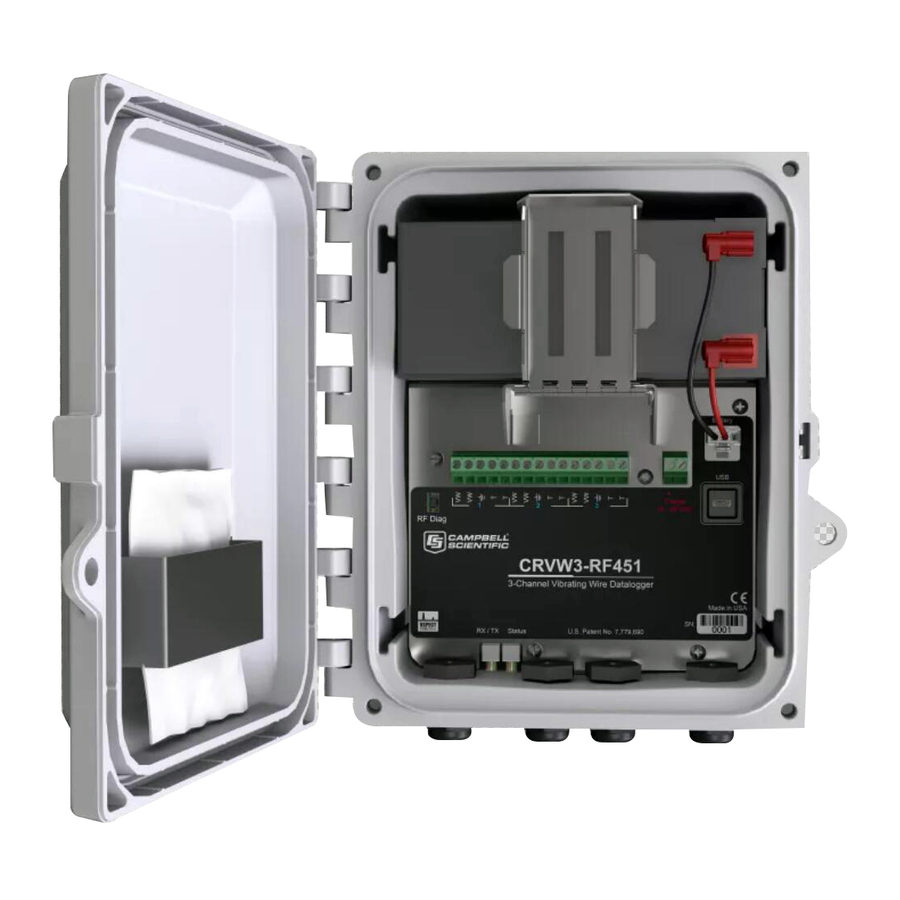
CRVW3 3-Channel Vibrating-Wire Datalogger Introduction The CRVW3 is a datalogger (Campbell recorder) that measures and stores readings from up to three vibrating-wire sensors. A temperature measurement (usually obtained from a thermistor built-in to the sensor) is also available for each of these three channels. Standard, single-coil-circuit vibrating-wire sensors are supported (purchased separately). -
Page 12: Cautionary Statements
No CRBasic programming is required. Frequency and temperature measurements are obtained at the specified measurement interval. Optional engineering output can be calculated using advanced settings. Additional information about the CRVW3 (pn 30243) can be found on the Campbell Scientific website: www.campbellsci.com/crvw3... -
Page 13: Initial Inspection
RF407 radio network, it may be necessary to deploy an RF450, RF451, or RF407 radio+modem device (in addition to those built-in to the CRVW3) to operate as the base radio station in the network. Please consult with your local Campbell Scientific support representative regarding the use of radio options. -
Page 14: Quickstart
For the –ALK option, this is an 8-cell battery pack along with 8 D-cell alkaline batteries. For the –RC option, this is a single rechargeable lead- acid 7 Ahr battery. If you received a CRVW3 with the –RC option, you should begin charging your rechargeable battery as soon as possible after receiving your shipment. -
Page 15: Overview
CRVW3 3-Channel Vibrating-Wire Datalogger Overview The CRVW3 is a rugged, field-ready datalogger for measuring vibrating-wire sensors. It provides built-in power options, including a charge regulator that enables direct solar panel connections. Built-in radio options are available to enable wireless communications, and the system comes inside an environmentally protective enclosure as a standard option. -
Page 16: Internal View Of A Typical Vibrating-Wire Piezometer Sensor
FIGURE 5-3. Internal View of a Typical Vibrating-Wire Piezometer Sensor The CRVW3 excites vibrating-wire sensors with a swept excitation (frequency-rich) waveform. The lowest frequency and highest frequency used in that excitation are customizable by the user. This frequency range represents... -
Page 17: About This Manual
Section 6, Specifications, contains key specifications relevant to the measurement and use of the CRVW3. Section 7, Installation, introduces the main installation issues applicable to the CRVW3. Section 8, Installation of Individual CRVW3 Stations, focuses on the installation of individual CRVW3 stations. -
Page 18: Specifications
Section 9, Radio Networks, and Section 10, Complex (Large) Radio Networks, discuss the planning and implementation of networks containing multiple CRVW3 stations that communicate with each other using radio telemetry. Section 11, Operation of CRVW3 Networks, Section 12, Maintenance of... -
Page 19: Installation
Installation For summarized installation information, refer to the Quick Deploy Guide (pn 31174) included with each CRVW3 as a folded card inside the enclosure. You can also view and download the Quick Deploy Guide from the Campbell Scientific website:... -
Page 20: Individual Devices And Radio Considerations
Individual Devices and Radio Considerations Each CRVW3 device can be deployed to the field as an independent data collection station. Additionally, radio communication options are provided to allow CRVW3 devices to communicate with each other, with repeater stations, and with a base radio station. -
Page 21: Lab Connection And Configuration
RF451), also refer to Section 9, Radio Networks. Lab Connection and Configuration When using a CRVW3 device in the lab or office, there are several key tasks to perform. A Microsoft Windows-based laptop or desktop computer (Personal Computer, i.e., PC) should be available. Electrical outlets or other power options, as well as vibrating-wire sensors for testing the device should also be on-hand. -
Page 22: Install The Crvw3 Usb Driver
DevConfig should automatically be installed during that process. 8.1.1.2 Install the CRVW3 USB Driver In order to make a wired communications connection between the CRVW3 and the PC, it is necessary to use a USB cable. This requires a driver to be installed on Windows in order to operate correctly. -
Page 23: Wiring Temporary Sensors To The Crvw3
9, Radio Networks, and Section 10, Complex (Large) Radio Networks. 8.1.2 Wiring Temporary Sensors to the CRVW3 Wiring sensors temporarily to the CRVW3 is necessary while in the lab to validate measurement operation. You can use the actual sensors (or similar) that will be used when the device is deployed to the field. -
Page 24: Wiring Panel Of The Crvw3
(energy input) and for reading out the current measurement (measurement output). These two leads should be connected to the two VW terminals on the CRVW3 corresponding to the desired measurement channel. The shield wire should be connected to the ground associated with that channel (located in between the VW terminals and the T terminals). -
Page 25: Providing Temporary Power To The Crvw3
A power source other than USB should be provided for the CRVW3 to make measurements properly and to enable radio communications. For CRVW3 devices with the radio option, the RX/TX LED is solid red when only USB power is provided to remind the user that the radio is not operating. -
Page 26: Crvw3 Usb Connection Location
Show Device Type Categories item in the Options menu is not selected, the devices will be listed alphabetically. Once selected, you should see a picture of the CRVW3 and connection instructions as shown below: Press the ellipsis button (…) next to the Communication Port box. This will list available COM ports on your system. - Page 27 Choose the Logger Control tab. You should see the Station Time update once every second. This behavior confirms that you have a good connection with the CRVW3 device. You may update the device’s clock to match the clock on the computer by using the Set Clock button.
-
Page 28: Configuring The Crvw3
[TabName – SettingName] Main- Station Name You can give a name to each CRVW3 station and store it in the device. When planning a network of multiple devices, station naming can assist you in the organization of your system. (See Planning your Network in Section 10.2, Planning the Radio Network.) - Page 29 PakBus address. You may wish to give a unique address to each CRVW3 even if it currently won’t be deployed as part of a radio network in case your communications usage on the device changes in the future. Set this address to a value between 1 and 3999.
- Page 30 Amplitudes of 2 V, 5 V, and 12 V can be selected. Longer cable lengths between a sensor and the CRVW3 may require a higher voltage setting. Sensors measured on a 3 second or shorter interval may require the lowest (2 V) voltage setting to avoid loss of resolution.
-
Page 31: Managing Changes To Settings
DevConfig screen becomes active. Press Apply to execute the changes on the device. The CRVW3 will be busy for up to 20 seconds to complete the changes. During that time you will not be able to connect to the CRVW3. -
Page 32: Testing The Measurement Operation Of The Crvw3
Use the LoggerControl tab to check the real-time clock of the device. The CRVW3’s clock can be synchronized with the PC clock using the Set Clock button. If the LoggerControl tab is unable to obtain the time from the CRVW3, then there are connectivity problems that need to be resolved (see Section 13, Troubleshooting CRVW3 Networks). - Page 33 CRVW3 3-Channel Vibrating-Wire Datalogger To ensure proper operation of the CRVW3, you should confirm that the RecordNo field of the VW_Data table is incrementing at the proper measurement interval, and that the measurement data (frequency, temperature) is correct. The Time Stamp field should also get updated as each measurement is made.
-
Page 34: Validating Radio Connectivity In The Lab
(*.bin). This file can be sent to Campbell Scientific support personnel (or to others) and then opened within DevConfig using the Offline Analysis tab that is shown when not connected to the CRVW3. This will allow others to assess the condition of your sensor measurement in detail. Use the Export button to save the results of the test into a text file that is readable using standard text editor programs. -
Page 35: Configuring The Rf450 Radio
• Radio Operation Mode: Multi-Point Master • Repeaters Used : leave unchecked • Network ID : This value should match the CRVW3 ID exactly ( 0 to 4095) • Frequency Key : Leave at 5 • Transmit Power : Leave at 10 •... -
Page 36: Using Devconfig To Connect To The Crvw3-Rf451 Over The Radio
The DevConfig screens should act just as they do when the computer has a wired connection to the CRVW3. You should be able to view and set all the settings of the CRVW3 over the radio connection. Confirm that the Serial Number and Station Name in the Main tab are correct and correspond to the CRVW3 station being tested. -
Page 37: Connecting Sensors To The Crvw3
Details about these tasks are provided in this section. When installing devices with a radio option, bring a radio device into the field that can operate as a radio base station. For the CRVW3-RF451 this is the RF450 device configured as the master radio and LoggerNet software running on a laptop computer. -
Page 38: Typical Vibrating-Wire Sensor Lead Colors And Connections
Scheme 2: Orange-coil-VW, Orange-White-coil-VW, Clear-shield-ground, Blue-thermistor-T, Blue-White-thermistor-T Determine which channel on the CRVW3 will be used for each sensor. Unscrew and remove the gland connector on the outside of the enclosure that corresponds to the channel currently being installed. Remove the gland capping pin, and then feed the removed gland connector over the bare leads on the end of the sensor cable and position it a few inches down the cable. -
Page 39: Providing Power To The Crvw3
When using this option, no solar panel or charge mechanism is required. However, visits to the site will be required on a regular basis to remove old batteries and insert new ones. The length of time that the CRVW3... -
Page 40: Alk Battery Pack Connector Cable And Crvw3 Battery Connection
(push on the metal backing for the hinge to snap out). Once the battery pack is removed from the enclosure, you can remove the old D-cells, and insert the new D-cells. The battery pack can then be placed back into the CRVW3 enclosure and the latch secured. Ensure that the bumpers on the pack contact the latch and that the battery pack does not wiggle when pressed. -
Page 41: Rechargeable Battery Option (-Rc)
CRVW3 3-Channel Vibrating-Wire Datalogger 8.2.2.2 Rechargeable Battery Option (–RC) If you selected the –RC option when ordering your CRVW3, then a 7 Ahr rechargeable battery is used to power the device. You will need a solar panel or some other DC voltage source (16 V to 28 V) to recharge the battery. Due to the power requirements of the –RF451 radio option, it is anticipated that... -
Page 42: Grid Power
8.2.2.3 Grid Power If grid power is available at the CRVW3 site, then that can be used as the main power source. Although the CRVW3 can operate exclusively from a proper voltage applied to its charge terminals, a battery option is still recommended for backup purposes and measurement continuity in case of power outages. -
Page 43: Humidity Monitoring And Control
8.2.4 Mounting the CRVW3 Enclosure The enclosure of the CRVW3 can be securely attached to a pole or other applicable mounting hardware. Use the supplied mounting kit (option –SM, included with CRVW3 shipment) or the Universal Mounting Bracket (pn 30840, –UM option, shown in FIGURE 8-12) to secure the CRVW3 enclosure... -
Page 44: Installing The Crvw3 Antenna
CRVW3. If the CRVW3 communicates with only one other radio station or device, use a directional antenna (such as a Yagi, pn 14201), and position the antenna so it points directly at the remote station. -
Page 45: Connecting The Crvw3 Electrical System To Earth Ground
27555) that was included in your CRVW3 shipment. Section 8.1.5, Configuring the CRVW3, discusses the basic configuration of a CRVW3 device. If no configuration of the CRVW3 for the current sensors has been previously performed, then first follow the steps outlined in that section to configure the CRVW3. -
Page 46: Confirming Crvw3 Sensor Measurement Operation
This validation includes the use of a laptop running DevConfig connected via USB cable. 8.2.8.1 LED Operation You can observe the LED behavior of the CRVW3 to assess its condition. The LED lights can be observed from both the inside and the outside of the enclosure. -
Page 47: Led Viewing Locations On The Crvw3
No Radio Activity Device asleep or powered down When the CRVW3 is powered up or has a change of settings applied, it executes its startup sequence. During the final stage of the startup sequence, you will see both LEDs in a solid orange state. Allow time for the startup sequence to complete (up to 20 seconds) before attempting to connect to the CRVW3. -
Page 48: Validation With Devconfig
The device then immediately returns to sleep, and therefore no “awake” indicator flashes (green or orange) will be observed between measurements. The CRVW3 will wake up (if not already awake) and remain awake as long as the USB cable is connected to the device. After the USB cable has been disconnected, the device will remain awake for five minutes, and then sleep between measurements. - Page 49 (including Campbell Scientific support personnel) for evaluation and troubleshooting purposes. Use the Off Line Analysis tab of DevConfig (shown when disconnected from the CRVW3) to open and view a file saved previously with the Save Last Results button. Refer to Section 8.1.6, Testing the Measurement Operation of the CRVW3, for more information about the operation of the Troubleshoot tab screen.
-
Page 50: Validating Crvw3 Radio Operation
CRVW3 3-Channel Vibrating-Wire Datalogger 8.2.9 Validating CRVW3 Radio Operation If you have a CRVW3 with a radio option (–RF451 or –RF407), then you should validate that the radio on the device is working properly before leaving the site. Use a laptop computer running DevConfig and LoggerNet with a USB connection to do this. -
Page 51: On-Site Manual Data Collection
On-site Manual Data Collection A technician located at a deployment site can use a USB cable to manually collect measured data from a CRVW3 using a Windows computer (laptop PC) and LoggerNet, PC400, or PC200W software. See Section 11.2.2, Manual Data Collection at the CRVW3 Site, for details about this data collection process. -
Page 52: Simple Radio Network Definition
To determine whether your needs can be met with a simple radio network, consider the following requirements: • The CRVW3 stations in the network should all have single-hop radio links to the base station no repeater stations should be required... -
Page 53: Simple Network Installation Overview
No measurements should be required to be made at the base station's • location The term “single-hop” refers to a CRVW3 station’s ability to make a radio connection directly with the base station without the need to route its radio communications through another radio-enabled station (i.e., no repeating is required). -
Page 54: Deploying Crvw3 End-Node Stations, Confirming Radio Connectivity
You should install individual radio-enabled CRVW3 devices at their field locations by following the instructions in Section 8.2, Field Deployment of the CRVW3. Ensure that the CRVW3-RF451 is configured as a Slave device using DevConfig. Do this from the Settings Editor tab in DevConfig. Choose the Radio tab. -
Page 55: Configuring Loggernet For Connectivity And Scheduled Collection
LoggerNet to use the base station according to the instructions in Section 9.3.3, Configuring LoggerNet for Connectivity and Scheduled Collection, and confirm that it can connect to and collect from the remote CRVW3 devices. This should be done before leaving the base station site and travelling to the remote LoggerNet location. -
Page 56: Complex (Large) Radio Networks
10. Complex (Large) Radio Networks As the number of radio-enabled CRVW3 devices increases, or as more complex terrain or other geographical constraints emerge within your system, then additional consideration must be given to radio network design and operation. -
Page 57: Base Radio Station
The purpose of a base radio station (also called a “base station”) is to be a gateway for communications between the radio network (which is your group of multiple CRVW3 stations) and other devices that communicate with them through some other communications medium. The LoggerNet computer is typically the most important device that communicates with your radio network via the base station. -
Page 58: Crvw3 End-Node Station
To operate as a repeater station, the radio of the CRVW3 must be configured as a repeater, and the IsRouter setting of the device should also be set to “true”... -
Page 59: Aggregating Datalogger Station
(using an RF407, RF451, or RF450). Once data is collected from the remote CRVW3 stations, it is stored on the datalogger (aggregated) so it can be retrieved later by LoggerNet or other data collection agents. It is possible for an aggregating datalogger station to also function as the base station of the network, but it is not required. -
Page 60: Sensor Side And Loggernet Side Of A Crvw3 Network
The location of the base station should also be determined. To bridge the two sides of the network, you should determine where you need to set up CRVW3 devices as repeater stations, and where you should introduce dedicated repeater stations. -
Page 61: Sensor Planning
CRVW3-based data collection networks. 10.2.1 Sensor Planning The ultimate objective of a CRVW3 network is to measure vibrating-wire sensors and relay that data back to LoggerNet. You should plan out, preferably using maps or other location-based diagrams, where each vibrating-wire sensor will be located. -
Page 62: Planning For Crvw3 End-Node Stations
FIGURE 10-4. Each Sensor Connects to a CRVW3 The length of cable between the sensor and the CRVW3 is a factor to consider. The distance between the CRVW3 and the measured sensor can be up to 1600 m in many instances. Long cable distances (> 500 m) should be validated for proper operation using careful field experimentation. -
Page 63: Repeater Planning
CRVW3 3-Channel Vibrating-Wire Datalogger If the remote station is within a close enough distance to the CRVW3, a whip antenna can be used. However, for longer distances a high-gain antenna will be needed. A Yagi antenna is recommended for a CRVW3 end-node station because of its high gain and directional beaming capability. -
Page 64: Planning The Base Station
The base station is located somewhere within range of the CRVW3 devices and the repeaters. The base station in this instance contains its main radio but also hosts another device. This can be an... -
Page 65: Planning Rf451 Radio Networks
10.2.6 Planning RF451 Radio Networks The CRVW3 can be purchased with the –RF451 communications option (i.e., as a CRVW3-RF451). This manual refers to the radio networks used by CRVW3-RF451 devices as RF451 radio networks. The following devices can be used to create a functioning station within an RF451 radio network: •... -
Page 66: Base Station Design For Rf451 Radio Networks
CRVW3 3-Channel Vibrating-Wire Datalogger Please refer to the RF450 manual for more information about the use of the RF450: s.campbellsci.com/documents/us/manuals/rf450.pdf Sections 3.9 and A.2 of the RF450 manual provide details about the configuration of RF450 dedicated repeater stations. 10.2.6.1 Base Station Design for RF451 Radio Networks For most base station designs on an RF451 radio network, the RF450 radio+modem device should be used. -
Page 67: Plan Validation And Hardware Procurement
CRVW3 3-Channel Vibrating-Wire Datalogger It is possible to designate the CRVW3 as the master radio of an RF451 radio network, and use it as the base station. This should only be done if a permanent USB cable connection can be maintained between the base CRVW3 and the LoggerNet computer. -
Page 68: Plan Validation With Others
Install and configure LoggerNet on a temporary or portable computer. Set up a base station, and confirm that it can communicate with a few CRVW3 stations. Set up a repeater station and ensure it works. Refer to Sections 10.4 through 10.7 for details about how this is done. -
Page 69: Field Deployment Considerations
(single-hop). In most cases it is helpful to install repeater stations and the CRVW3 devices that require them at the end of your deployment cycle. By ensuring during the first part of your deployment that single-hop CRVW3 devices are operating properly with the base station and with LoggerNet, then the level of complexity is reduced for the repeater station validation process. -
Page 70: Deployment Of Crvw3 Radio Stations
You may need to experiment with antenna height to get the best link strength possible (see Section 10.2.7.1, Pre-procurement Field Visits). If the CRVW3 station will operate as a repeater station, see instructions in Section 10.6, Repeater Station Deployment. When several or all of the CRVW3 end-node stations have been installed and confirmed as working, then connectivity with the permanent base station should be validated at the base station location. -
Page 71: Base Station Deployment
10.5 Base Station Deployment The base radio station used in a CRVW3 network has two communications pathways. One is the radio pathway that is used to communicate with CRVW3 end-node stations and repeater stations. The other is the pathway to LoggerNet and other remote devices that may require connectivity with the radio network. -
Page 72: Base Station On The Rf451 Network
A CRVW3 device itself is not usually used as the base station in a CRVW3 network. This should only be done if a permanent USB cable connection can be maintained between the base CRVW3 and the LoggerNet computer. -
Page 73: Repeater Station Deployment
CRVW3 3-Channel Vibrating-Wire Datalogger As indicated in Section 10.2.6.1, Base Station Design for RF451 Radio Networks, the CRVW3 itself is rarely used as the base radio station in an RF451 Network. However, to use that configuration, ensure that the Radio Operation Mode setting in the Radio tab of DevConfig is set to Point to MultiPoint Master. -
Page 74: Loggernet Configuration
CRVW3 stations. The Setup (Setup Screen) program in LoggerNet is used to create a tree-list of CRVW3 stations and their connectivity attributes, as well as details for related hardware. This list of devices shows in multiple locations throughout the software and is called the Network Map of LoggerNet. - Page 75 CRVW3 3-Channel Vibrating-Wire Datalogger The Setup application is found on the Main section of the Toolbar which appears when LoggerNet is first started. Click the blue “wrench and screwdriver” icon to start the application: If the Setup Screen comes up in the EZSetup Mode,...
- Page 76 CRVW3 3-Channel Vibrating-Wire Datalogger First, add a root device to the network map by pressing the Add Root button. When using a serial cable (local) connection to the base station, then you should select ComPort for the type of root device. If you have a telemetry connection between LoggerNet and the base station, you will usually choose IPPort as the root device.
- Page 77 (see Section 10.2, Planning the Radio Network). In the Hardware tab, set the PakBus Address value to match up with the value that was configured into the actual CRVW3 device with DevConfig or with the Network Planner. Press Apply.
- Page 78 Clock. If the clock check executed successfully, then the set clock operation should also work, otherwise troubleshooting may be needed. To add additional CRVW3 devices to your network map, you don’t need to add a ComPort, IPPort or PakBusPort again. Simply click on the existing...
-
Page 79: Connecting To Crvw3 Stations
CRVW3 device that has been configured as a repeater station and press Add. Choose CRVWSeries from the datalogger list and press Close. Now you have a CRVW3 device showing up as a child device of the CRVW3 repeater. This will instruct LoggerNet to route through the CRVW3 repeater to get to the CRVW3 child device. - Page 80 CRVW3 3-Channel Vibrating-Wire Datalogger The Stations list shows all CRVW3 devices that have been defined on your network map. Click on a station and press the Connect button in the upper left corner to establish a communications session to the station. If the radio link is healthy and LoggerNet is configured correctly, you will see a successful connection to the device and the button’s icon will change to show a connected...
-
Page 81: Setting Up Automatic Data Collection
10.7.4 Setting up Automatic Data Collection With a good connection working to every CRVW3, you can now set up automatic data collection (also called scheduled data collection) in LoggerNet for each station/device. To do this, use the SetupScreen application (see Section 10.7.2, Configuring the Network Map of LoggerNet). -
Page 82: Monitoring Automatic Data Collection
11.1 Monitoring Automatic Data Collection Most CRVW3 devices that have been configured to be part of a radio network will also be part of an automatic collection schedule that is executed by the LoggerNet software. For more information about configuring LoggerNet to use automatic data collection (Scheduled Data collection), see Section 10.7.4,... - Page 83 There is also a table called CalHist that stores calibration information, if that is used on the device. The VW_Data table is the final storage table used by the CRVW3. It is the permanent repository of measurements made, and includes frequency data and temperature data (when applicable).
-
Page 84: Manual Data Collection
For those cases, manual data collection can be used. It is also possible to retrieve data from a CRVW3 using manual collection when a technician visits the CRVW3 field site. -
Page 85: Manual Data Collection At The Crvw3 Site
Section 5.1.2.2 of the LoggerNet manual. 11.2.2 Manual Data Collection at the CRVW3 Site A technician located at a CRVW3 deployment site can use a USB cable to manually collect data from a CRVW3 using a Windows computer (laptop PC) running LoggerNet, PC400, or PC200W software. -
Page 86: Station Health Monitoring
EZSetup wizard. Ensure that the USB driver creates a ComPort that references your USB cable connection, and which is specified in EZSetup. Once you can connect to the CRVW3, then choose the Collect Data tab from the main screen of PC400 or PC200W. Refer to the PC400 documentation (Section 4.4) or PC200W on-line help for details about using the Collect Data... -
Page 87: Processing Collected Data
LoggerNet. This works for data collected via automatic collection or via Collect Now. Once connected, use the Table Monitor dropdown to select one of the CRVW3 tables for display. Use the Num Display button to open and configure a numeric display monitor. This allows data from more than one table to be displayed. - Page 88 .DAT file available on the computer. You can look up the location of various .DAT files by looking at the Data Files tab for each CRVW3 in the SetupScreen application. For more information about using View Pro, refer to Section 8.1 of the LoggerNet manual.
-
Page 89: Maintenance Of Crvw3 Networks
Calibration Wizard. 12.1.1 Battery Monitoring The status of the battery on the CRVW3 should be monitored using the Battery field in the Status table. Voltage levels greater than 12 V indicate that the charge circuit is active and charging the battery. Levels of 12 V or less... -
Page 90: Sensor Spectrum Checks
Troubleshoot tab in DevConfig (see Section 8.1.6, Testing the Measurement Operation of the CRVW3, and Section 8.2.8.2, Validation with DevConfig). There is a way to make a similar spectrum check on a CRVW3 using LoggerNet and a remote connection (i.e., if the device has a radio option). - Page 91 11. Open DevConfig, choose CRVW Series for the device, select the Off Line Analysis tab. Press the Read File button, and browse to the TimeSeries.bin file. 12. The contents of the file will be processed, and DevConfig will display the spectrum and time-series information as recorded by your remote CRVW3...
-
Page 92: Adjusting Device Settings
Rename the various files as needed to indicate the station and channel that they represent. It is recommended that some TimeSeries.bin files be captured soon after the installation of a CRVW3 station so that they can be kept as baseline references that document how the sensor was operating at the time of deployment. -
Page 93: Crvw3 On-Site Maintenance Visits
12.2 CRVW3 On-site Maintenance Visits It is wise to schedule periodic visits to the deployment site of a CRVW3 station. Consider making a visit to inspect each CRVW3 station after the winter season (in climates where heavy cold-weather precipitation occurs or where extreme temperatures occur). -
Page 94: Troubleshooting Crvw3 Networks
LoggerNet (see Section 10, Complex (Large) Radio Networks). Using the Terminal mode of the CRVW3 from DevConfig can also be used to perform maintenance (see Appendix B, Terminal Mode from Connect Screen or DevConfig). -
Page 95: Troubleshooting Problems Remotely Using Loggernet
LoggerNet also has a LogTool utility that shows low-level text messages about how LoggerNet is operating and attempting to connect and interact with CRVW3 stations. These logs can be captured and sent to your support representative for evaluation. LoggerNet also has a TroubleShooter utility that helps to identify communication problems. - Page 96 Refer to Section 10, Complex (Large) Radio Networks, for details that will help troubleshoot radio connectivity problems. Use a portable base station (RF450 and laptop) to ensure you can communicate with the CRVW3 over its radio. It may be necessary to visit the base station or a repeater station to fully investigate radio network problems.
-
Page 97: Updating Crvw3 Firmware
CRVW3 OS under certain circumstances. The OS is packaged as an *.obj file. This file can be sent to the CRVW3 using DevConfig or LoggerNet. When the CRVW3 receives an *.obj file, the update of the firmware is triggered automatically. - Page 98 4. Browse to the *.obj file, select it and press Open. 5. Carefully review the warning, press OK if no further preparation is needed, otherwise Cancel. 6. The file is sent over the radio link to the remote CRVW3 and the OS update occurs automatically.
- Page 99 CRVW3 3-Channel Vibrating-Wire Datalogger 7. After the OS is sent, a period of about 25 seconds is required for the CRVW3 to fully load the OS and restart itself. Do not attempt to connect to the device during this time.
- Page 100 Appendix A. Updating CRVW3 Firmware...
-
Page 101: Terminal Mode From Connect Screen Or Devconfig
Appendix B. Terminal Mode from Connect Screen or DevConfig You can use the terminal mode of a CRVW3 datalogger to perform troubleshooting and configuration of the device. You should usually have contact with Campbell Scientific support personnel before using this feature. - Page 102 Appendix B. Terminal Mode from Connect Screen or DevConfig...
-
Page 103: Aggregating Dataloggers
An aggregating datalogger can also be configured as the base radio station, but that is not required. To be a part of the radio network, a radio that is compatible with the CRVW3 radio network must be integrated to the datalogger. This will be an RF450 radio+modem device, an RF451 device, or an RF407 device. -
Page 104: Programming The Aggregator
The datalogger will collect the VW_Data table from each CRVW3. In order for this to work properly, the definition of the table in the CRVW3 and in the datalogger program must match each other. To obtain this table definition (a DataTable/EndTable structure) you must execute the “show table structure”... - Page 105 'The following declarations and table definitions were extracted 'from the CRVW3 terminal mode's "show table structure" command. 'Note that if you change settings on the CRVW3, these definitions 'could also change, and so they would need to be re-extracted 'from the terminal mode again and re-inserted into the program...
-
Page 106: Getdatarecord Sample Program
'to avoid a -7 table signature mismatch code (returned to GDRResult1/2) 'See the GetDataRecord CRBasic help topic for more details. 'The PakBus address of the CRVW3 is "4", the PakBus neighbor to route through is "2" 'The radio is connected to the CS I/O SDC7 port+channel... -
Page 107: Engineering Output And Calibration
E.1 Engineering Output The frequency reading on the CRVW3 is expressed both in units of Hertz (Hz) and in units of digits (Hz /1000). The CRVW3 can be configured to calculate an output value that is specified in engineering units (in units of measure or dimensions). -
Page 108: Calibration Of Sensors
DevConfig help topics for each coefficient setting listed in the above table. Once the settings have been applied and the CRVW3 restarts, the calculated output in engineering units will be given in the ChanX_EngOut value of the VW_Data output table, where X represents the channel number or ChanX is the name you gave to the sensor/channel. - Page 109 The Use Ambient Pressure Correction setting controls whether engineering output will be adjusted using the current atmospheric pressure value that is stored in certain variables in the Public table of the CRVW3. The public variable’s value will be subtracted from the calculated engineering result to give the final engineering output.
- Page 110 Appendix E. Engineering Output and Calibration...
- Page 112 • info@campbellsci.com.cn • info@campbellsci.de www.campbellsci.com www.campbellsci.de Campbell Scientific do Brasil Ltda. (CSB) Campbell Scientific Spain, S. L. (CSL Spain) Rua Apinagés, nbr. 2018 ─ Perdizes Avda. Pompeu Fabra 7-9, local 1 CEP: 01258-00 ─ São Paulo ─ SP 08024 Barcelona...
Need help?
Do you have a question about the CRVW3 and is the answer not in the manual?
Questions and answers