Table of Contents
Advertisement
Quick Links
Advertisement
Table of Contents

Subscribe to Our Youtube Channel
Related Manuals for Campbell CRVW3


Summary of Contents for Campbell CRVW3
- Page 1 Revision: 03/2023 Copyright © 2015 – 2023 Campbell Scientific CSL I.D - 1158...
- Page 2 Quotations for repairs can be given on request. It is the policy of Campbell Scientific to protect the health of its employees and provide a safe working environment, in support of this policy a “Declaration of Hazardous Material and Decontamination”...
- Page 3 About this manual Please note that this manual was originally produced by Campbell Scientific Inc. primarily for the North American market. Some spellings, weights and measures may reflect this origin. Some useful conversion factors: Area: 1 in (square inch) = 645 mm Mass: 1 oz.
- Page 4 • Periodically (at least yearly) check electrical ground connections. WHILE EVERY ATTEMPT IS MADE TO EMBODY THE HIGHEST DEGREE OF SAFETY IN ALL CAMPBELL SCIENTIFIC PRODUCTS, THE CUSTOMER ASSUMES ALL RISK FROM ANY INJURY RESULTING FROM IMPROPER INSTALLATION, USE, OR MAINTENANCE OF TRIPODS, TOWERS, OR ATTACHMENTS TO TRIPODS AND TOWERS...
-
Page 5: Table Of Contents
7.7 Validating radio connectivity in the lab 7.7.1 Validating CRVW3–RF451/RF452 radio connectivity 7.7.1.1 Configuring the base RF451/RF452 7.7.1.2 Configuring the CRVW3–RF451/RF452 7.7.1.3 Using Device Configuration Utility to connect to the CRVW3– RF451/RF452 over the radio Table of Contents - i... - Page 6 7.7.2 Validating CRVW3–RF407 radio connectivity 7.7.2.1 Configuring the baseRF407 7.7.2.2 Configuring the CRVW3–RF407 7.7.2.3 Using Device Configuration Utility to connect to the CRVW3–RF407 over the radio 8. CRVW3 field deployment 8.1 LED indicators 8.2 Connecting sensors to the CRVW3 8.3 Providing power to the CRVW3 8.3.1 Alkaline D cell option (–ALK)
- Page 7 11. Troubleshooting 11.1 Using LoggerNet to remotely troubleshoot problems 11.1.1 Status monitor 11.2 CRVW3 site visits to troubleshoot problems Appendix A. Updating the operating system A.1 Sending an operating system to a local data logger A.2 Sending an operating system to a remote data logger A.3 CRVW3 maintenance with LoggerNet...
-
Page 8: Introduction
1. Introduction The CRVW3 is a data logger that measures and stores readings from up to three vibrating-wire sensors. A temperature measurement, usually obtained from a thermistor built into the sensor, is also available for each of these three channels. Separately purchased, single-coil-circuit vibrating-wire sensors are also supported. - Page 9 Multiple built-in CRVW3 radio options (–RF407, –RF412, –RF422, –RF427, –RF451, and –RF452) are available to enable the creation of wireless networks. All radio options except the CRVW3– RF427 are available in both enclosure and non-enclosure versions; CRVW3–RF427 is only available in the non-enclosure version.
- Page 10 The CRVW3 –RF407, –RF412, –RF422, and –RF427 options are all versions of the same radio series. This manual will refer to a CRVW3 with any of these options as “CRVW3–RF407.” The standalone radios will be referred to collectively as “RF407.” Throughout this manual, RF407 can be replaced with RF412, RF422, or RF427, unless otherwise noted.
-
Page 11: Precautions
WARNING: Close the lid of the enclosure and secure the latch when the CRVW3 is deployed to avoid unwanted water entry and provide isolation from other environmental factors. IP66 protection is available when using the four screws provided by the enclosure manufacturer to seal the lid properly. -
Page 12: Initial Inspection
NOTE: When using multiple CRVW3 devices in an RF451/RF452 or RF407 radio network, it may be necessary to deploy an RF451/RF452 or RF407 device, in addition to those built into the CRVW3, to operate as the radio base station in the network. Please consult the radio-specific manuals for more information relating to the design and configuration of radio networks. -
Page 13: Measurement Theory
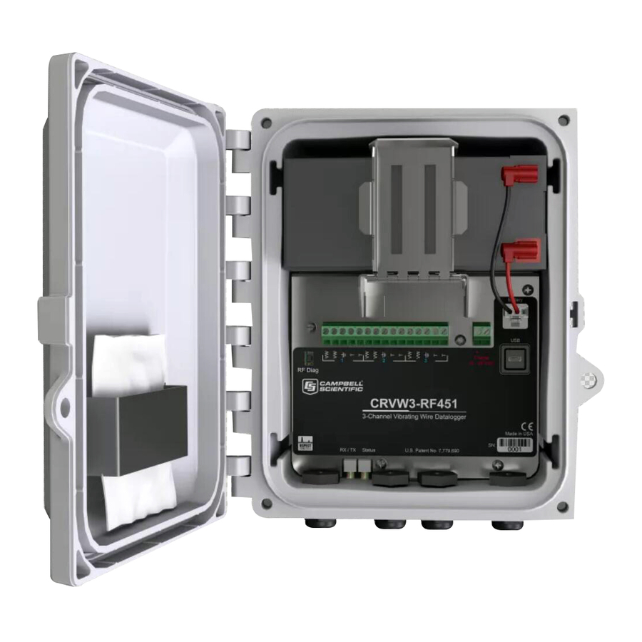
Figure 4-1. Basic CRVW3 parts 4.1 Measurement theory A vibrating-wire sensor is designed so that its output corresponds to changes of the phenomenon in the environment that is being measured. This is done by converting environmental changes into changes of the tension on a suspended metal wire, which is located inside the sensor. -
Page 14: Vspect
Using this information, you will formulate both a low frequency value and high frequency value to be configured into the CRVW3. This frequency range is used during excitation and during the read-back of the sensor: only energies within the specified frequency range are used for excitation, and only frequencies within the window are processed during sensor response read-out. - Page 15 While the graphs on the right show an electrically noisy environment (AC power) similar to what can be seen in a field environment (power lines, motors, radio signals, etc.). CRVW3 3-Channel Vibrating-Wire Data Logger...
-
Page 16: Specifications
5. Specifications All CRVW3 data loggers are tested and guaranteed to meet the following electrical specifications in a –40 to 70 °C non-condensing environment: 5.1 Data logger... - Page 17 16 to 28 VDC from solar panel or DC power converter Battery options: Rechargeable 7 Ah or 8 D cell alkaline Physical Weight: 4.2 kg (9.2 lb) with rechargeable battery or 3.0 kg (6.6 lb) with alkaline batteries Operating temperature range: –40 to 70 °C CRVW3 3-Channel Vibrating-Wire Data Logger...
-
Page 18: Radio Option
RF422: 2 to 25 mW RF427: 5 to 250 mW RF451/RF452: 10 mW to 1,000 mW Channel capacity RF407: Eight 25-channel hop sequences sharing 64 available channels. RF412: Eight 25-channel hop sequences sharing 31 available channels. CRVW3 3-Channel Vibrating-Wire Data Logger... -
Page 19: Installation Considerations
6. Installation considerations For summarized installation information, refer to the Quick deploy guide included with each CRVW3 inside the enclosure. You can view and download it from: s.campbellsci.eu/documents/us/manuals/crvw3-quick-deploy-guide.pdf Preconfigure and test your measurement system before deployment in the field. Issues that are unresolved before deployment are often more difficult to resolve. -
Page 20: Individual Devices And Radio Considerations
This enables CRVW3 devices to interact from the field with LoggerNet software running in the lab, office, or other IT-hosted location. Automatic data collection, performed without technician field visits, is one of the most useful benefits provided by a radio network configuration of multiple CRVW3 devices. -
Page 21: Software Requirements
No measurements should be required at the base station location. The term “single-hop” refers to the ability of a CRVW3 station to make a radio connection directly with the base station without the need to route its radio communications through another radio- enabled station (in other words, no repeating is required). -
Page 22: Preconfiguring Crvw3 Stations
7.1 Lab software configuration For CRVW3 lab operations, you will need a Windows computer with administrative privileges. The following steps only need to be done once. 1. Install the latest version of LoggerNet... -
Page 23: Network Planner
Key settings (p. 21) for an explanation of the required communications and vibrating wire settings. After a design is complete, Network Planner can be used to automatically configure each device that is part of the system. CRVW3 3-Channel Vibrating-Wire Data Logger... -
Page 24: Wiring Temporary Sensors To The Crvw3
Consider that any sensors connected in the lab may need to be disconnected from the CRVW3 when the system is transported to the field location. Turn off the CRVW3 before wiring sensors to it. This includes removing the USB cable, if connected. - Page 25 Polarity is not a consideration for wiring to the two VW terminals or the two T terminals. The following table and figure show typical sensor wire colours and connections. Table 7-1: Sensor wire colour, function, and CRVW3 connection Label Description...
-
Page 26: Providing Temporary Power To The Crvw3
7.3 Providing temporary power to the CRVW3 To provide temporary power to the CRVW3 while in the lab, it is recommended that you use a 16 to 28 VDC power supply. Connect the power wires to the Charge terminals. Figure 7-3. Power source connection If your CRVW3 uses the –ALK option, you can disconnect that power source to preserve battery... -
Page 27: Connecting To The Crvw3
7.4 Connecting to the CRVW3 Before connecting to the CRVW3 via USB, ensure that the USB driver is installed as described in Lab software configuration (p. 15). After the driver is installed on a particular computer, it should be available for all future connections. Use a USB cable to connect the computer to the CRVW3. -
Page 28: Configuring The Crvw3
WARNING: Collect all data from the CRVW3 before changing any settings. Applying changes to certain CRVW3 settings may cause the CRVW3 to reset its operating mode or change its table structure and can result in data being erased. 7.5.1 Key settings [TabName >... - Page 29 “hops.” When a CRVW3 station performs these relay functions, it is known as a radio repeater and functions as a PakBus router. Set the Is Router setting to True when the CRVW3 will be used in this way.
- Page 30 A, B, and C (given as the three settings following the Thermistor Enabled setting). This will result in a temperature output in units of degrees Celsius. Setting the three coefficient values to 0 will result in only the resistance in ohms as an output CRVW3 3-Channel Vibrating-Wire Data Logger...
-
Page 31: Managing Changes To Settings
(p. 51) for more details about these settings. 7.5.2 Managing changes to settings Once you have made changes to the CRVW3 settings, click Apply at the bottom of the Device Configuration Utility screen to save the settings. The CRVW3 will be busy for up to 20 seconds while applying the changes. -
Page 32: Testing Crvw3 Measurements
Click on a table name in the left pane to see its latest stored record in the right pane. The Status table shows general information about the CRVW3 and its operation. The Public table shows information about specific variables in use by the current program configuration. - Page 33 4. Use the Troubleshoot tab to see detailed information about the vibrating-wire sensor measurements made by the CRVW3. Manually trigger a measurement test and see diagnostic results within a few seconds. Select your Channel and click Options to set a test sweep excitation and frequency filtering window, and the excitation voltage level.
-
Page 34: Validating Radio Connectivity In The Lab
Click Export to save the results of the test into a text file. 9. Use the Terminal tab to make a terminal mode connection to the CRVW3. This is typically used under the direction of Campbell Scientific support personnel. See Terminal mode 75) for more information. -
Page 35: Configuring The Base Rf451/Rf452
LoggerNet configuration (p. 53). NOTE: If testing the radio connectivity of multiple CRVW3–RF451/RF452 devices, only turn on one CRVW3–RF451/RF452 at a time when using this test method. 7.7.1.1 Configuring the base RF451/RF452 Radios are configured using Device Configuration Utility. See Figure 7-5 (p. - Page 36 It may take a few seconds for the Communication Port to become available for use after physically connecting the RF451/RF452 to your computer. 6. Click Connect. The radio Status LED will turn yellow. After several seconds, a screen similar Figure 7-6 (p. 29) will appear: Figure 7-6. RF451/RF452 settings CRVW3 3-Channel Vibrating-Wire Data Logger...
- Page 37 Transmit SubNet ID Leave at 15 Radio ID Must be unique for each radio device; use 1 (CRVW3 will use 0) 8. Click Apply. 9. Leave the USB cable connected to the USB port of the RF451/RF452 and the computer.
-
Page 38: Configuring The Crvw3-Rf451/Rf452
1. Provide power to the CRVW3 as described in Providing temporary power to the CRVW3 19). 2. Connect the CRVW3 and computer using a USB cable. 3. In Device Configuration Utility, choose CRVW Series, select the CRVWx Communication Port. Connect. -
Page 39: Using Device Configuration Utility To Connect To The Crvw3- Rf451/Rf452 Over The Radio
RF451/RF452/COM port on the computer as a transparent link. The Device Configuration Utility screens should behave the same as when there is a wired connection between the computer and CRVW3. You should be able to view and set all the settings of the CRVW3 over the radio connection. -
Page 40: Validating Crvw3-Rf407 Radio Connectivity
7. Use the Data Monitor tab to confirm proper CRVW3 operation. NOTE: If multiple CRVW3 devices need to be powered and located within radio range of the RF451/RF452 base station computer, you must use LoggerNet to test their radio connectivity. - Page 41 RF407 (COM#) where # is the COM port number. NOTE: It may take a few seconds for the Communication Port to become available for use after physically connecting the RF407 to your computer. CRVW3 3-Channel Vibrating-Wire Data Logger...
- Page 42 Click Read File to load the settings in Device Configuration Utility. Then click Apply to save your changes to load the settings into the radio. CRVW3 3-Channel Vibrating-Wire Data Logger...
-
Page 43: Configuring The Crvw3-Rf407
1. Provide power to the CRVW3 as described in Providing temporary power to the CRVW3 19). 2. Connect the CRVW3 and computer using a USB cable. 3. In Device Configuration Utility, choose CRVW Series, select the CRVWx Communication Port. Connect. -
Page 44: Using Device Configuration Utility To Connect To The Crvw3-Rf407 Over The Radio
RF451/RF452/COM port on the computer as a transparent link. The Device Configuration Utility screens should act just as they do when the computer has a wired connection to the CRVW3. You should be able to view and set all the settings of the CRVW3 over the radio connection. -
Page 45: Crvw3 Field Deployment
7. Use the Data Monitor tab to confirm proper CRVW3 operation. NOTE: If multiple CRVW3 devices need to be powered and located within radio range of the RF407 base station computer, you must use LoggerNet to test their radio connectivity. LoggerNet can distinguish between CRVW3 devices based on PakBus address. -
Page 46: Led Indicators
8.9.1 Radio power schedule 8.10 Sealing the CRVW3 enclosure 8.1 LED indicators The CRVW3 LEDs give an indication of its state. See the following figure for LED locations inside and outside of the enclosure. Table 8-1 (p. 40) summarizes LED operation. -
Page 47: Connecting Sensors To The Crvw3
Install the vibrating-wire sensors according to manufacturer supplied instructions. A 5-wire or 3- wire cable will connect between each sensor and the CRVW3. Vibrating-wire sensors containing a built-in thermistor will have five wires. Sensors without a built-in thermistor will have three wires. - Page 48 1. Determine which channel on the CRVW3 will be used for each sensor. 2. Unscrew and remove the connector on the outside of the enclosure that corresponds to the channel currently being installed. 3. Remove the capping pin. 4. Feed the removed connector over the bare wires on the end of the sensor cable, and position the connector a few inches down the cable.
-
Page 49: Providing Power To The Crvw3
The CRVW3 will wake up (if not already awake) and remain awake as long as the USB cable is connected to the device. After the USB cable has been disconnected, the device will remain awake for five minutes, then sleep between measurements. -
Page 50: Alkaline D Cell Option (-Alk)
Turn on the CRVW3 by connecting the battery connector to the CRVW3 as shown in the following figure: Figure 8-3. –ALK battery pack connection You should immediately see LED activity on the CRVW3. If no LED activity is observed, then check and replace the batteries if necessary. See LED indicators (p. -
Page 51: Ac Line Power
8.3.3 AC line power The CRVW3 device can operate using AC line power as the main power source. However, it is still recommended to have a rechargeable battery (with the –RC option) as a backup source in case of power outages. -
Page 52: Humidity Monitoring And Control
The humidity indicator card is a single-use card and should be replaced after one or more of its coloured circles turn pink. 8.5 Mounting the CRVW3 enclosure The CRVW3 enclosure can be securely attached to a pole or other surface. Figure 8-5 (p. 45) shows the CRVW3 with the –UM option installed. -
Page 53: Installing The Crvw3 Antenna
These antennas require mounting hardware (such as a pole) separate from the CRVW3. If the CRVW3 communicates with only one other radio station or device, use a directional Yagi antenna, and position it to point directly at the remote station. If the CRVW3 communicates with more than one radio station or device (for example, when it is configured to operate as a repeater station), an omnidirectional antenna should be used. -
Page 54: Connecting The Crvw3 To Earth Ground
Connect the ground lug to an adequate earth/soil connection using a low-gauge wire (8 to 12 AWG) that accommodates high current flows. Figure 8-7. CRVW3 ground lug location A Basic Grounding Kit for Small Enclosures from Campbell Scientific can be used to make this connection. 8.7.1 Electrostatic discharge protection Electrostatic discharge (ESD) can originate from several sources, the most common and destructive being lightning strikes. -
Page 55: Lightning Protection
8.8 Validating and fine-tuning CRVW3 settings Before completing the deployment of your CRVW3, confirm it is operating in the way you expect. Bring a computer running Device Configuration Utility with you in the field so you can connect to and adjust device settings. -
Page 56: Confirm Crvw3 Sensor Measurements
Using Device Configuration Utility, confirm the following settings: Station Name Measurement interval PakBus Address Is Router (should be set to True when CRVW3 is also a radio repeater) Radio settings Refer to Configuring the CRVW3 (p. 21) if any settings need to be adjusted. If you previously saved the configuration summary through Device Configuration Utility, you can restore them by clicking Read File then Apply. - Page 57 (baseline or datum point) for comparison with future behaviour of the same sensor. 11. Use the Off Line Analysis tab when disconnected from the CRVW3 to open and view a file saved previously. See Testing CRVW3 measurements (p.
-
Page 58: Validating Crvw3 Radio Operation
CRVW3 to avoid radio frequency (RF) interference that can impede communications. 8.9.1 Radio power schedule A CRVW3 with a radio option can be configured to turn on and off at certain times during the day. This is done using the Radio Power Schedule tab in Device Configuration Utility. For example, use the following settings to turn the radio on for 15 minutes at midnight, 6:00 AM, noon, and 6:00 PM. -
Page 59: Sealing The Crvw3 Enclosure
When the shut-off time is reached, the radio will stay on long enough to complete any current transactions, then turn off. A USB cable connected to the CRVW3 device will override the Radio Power Schedule by turning on the radio and keeping it on for as long as the cable is connected. -
Page 60: Loggernet Configuration
CRVW3 devices on your network, enabling connectivity. Once you can connect to and collect data manually from each CRVW3 station on your network, configure LoggerNet to collect data automatically, also known as scheduled data collection. -
Page 61: Loggernet Network Map Configuration
NOTE: If Network Planner was used to configure your network of CRVW3 devices, you can use a function in that software to configure the network map of LoggerNet so that it can communicate with the base station and the CRVW3 devices. Note the checkbox for configuring LoggerNet located in the Configure Devices checklist on the main screen. - Page 62 4. Select PakBusPort (PakBus Loggers). 5. Select CRVWSeries. 6. Click Close. If you started with an empty network map, your Entire Network should look similar to the following image. 7. Click ComPort in the Entire Network pane. CRVW3 3-Channel Vibrating-Wire Data Logger...
- Page 63 10. (IP option) Click IPPort device in the Entire Network pane. 11. On the Hardware tab, in the Internet IP Address box, enter the TCP/IP address and port number used to connect to your telemetry device at the base station location. 12. Click Apply. CRVW3 3-Channel Vibrating-Wire Data Logger...
- Page 64 13. Click CRVWSeries in the network map.Click Rename and enter a device name. 14. On the Hardware tab, set the PakBus Address value to match the value that was configured into the CRVW3 device with Device Configuration Utility or with the Network Planner. 15. Click Apply.
- Page 65 17. Click Check Clocks button to instruct LoggerNet to send a clock check command through the base station to the destination CRVW3 station. If the radio link is working, the current date and time should show up in the Adjusted Server Date/Time and Station Date/Time boxes within a few seconds.
-
Page 66: Connecting To Crvw3 Stations
Click Apply in each case. 20. To add CRVW3 devices that are reached through a CRVW3 repeater station, click on the CRVW3 device that has been configured as a repeater station and click Add. Choose CRVWSeries from the data logger list and click Close. -
Page 67: Setting Up Automatic Data Collection
Status table of the device. 7. Click Collect Now to confirm that data can be collected from each CRVW3 station. 8. Use the Connect Screen to validate that every CRVW3 station is fully functional and communicating. 9.4 Setting up automatic data collection When LoggerNet is running and scheduled collection is enabled, LoggerNet will automatically connect to a specified station at a designated time and collect data from it. -
Page 68: Maintenance
NOTE: It is possible to convert a CRVW3 from the –RC option to the –ALK option and vice versa. This involves obtaining the desired battery or battery pack from Campbell Scientific and reversing the latch that secures the battery within the enclosure. -
Page 69: Sensor Spectrum Checks
During installation or during on-site maintenance, this can be done using the Troubleshoot tab in Device Configuration Utility. Making a similar spectrum check on a CRVW3 using LoggerNet and a remote connection if the device has a radio option is also possible. The creation of a binary file can be triggered, and then that file can be retrieved to the LoggerNet computer station using File Control. - Page 70 9. Select only the file TimeSeries.bin and click Retrieve…. 10. Save the file. 11. Open Device Configuration Utility, choose CRVW Series for the device, and select the Off Line Analysis tab. Click Read File and browse to the TimeSeries.bin file. CRVW3 3-Channel Vibrating-Wire Data Logger...
-
Page 71: Device Settings Adjustments
It is recommended that some TimeSeries.bin files be captured soon after the installation of a CRVW3 station so they can be kept as baseline references that document how the sensor was operating at the time of deployment. -
Page 72: Crvw3 On-Site Maintenance Visits
6. Close the Settings screen, since it is no longer connected to the CRVW3. Allow up to 20 seconds to elapse before you can expect to communicate with the CRVW3 again. You may need to reconnect to the device in Connect Screen. -
Page 73: Internal Battery
(p. 75). 10.3 Internal battery The lithium battery powers the internal clock and SRAM when the CRVW3 is not powered. This voltage is displayed in the Status table RTC_Battery field. Replace the battery when voltage is approximately 2.7 VDC. The internal lithium battery life is extended when the CRVW3 is installed with an external power source. -
Page 74: Troubleshooting
WARNING: Any damage made to the CRVW3 during user replacement of the internal battery is not covered under warranty. NOTE: The battery is replaced during regular factory recalibration, which is recommended every 3 years. When the lithium battery is removed (or is depleted and primary power to the data logger is removed), the CRBasic program and most settings are maintained, but the following are lost: Run-now and run-on power-up settings. -
Page 75: Using Loggernet To Remotely Troubleshoot Problems
11.1 Using LoggerNet to remotely troubleshoot problems Sometimes you can still communicate with the CRVW3 station, but its measurements make little or no sense or work only intermittently. In those cases, you can connect to the station and check the spectrum to see if a sensor problem exists with sensor cabling, connectivity, operation, or noise/interference to name a few examples. -
Page 76: Status Monitor
11.1.1 Status monitor Most CRVW3 devices that have been configured to be part of a radio network will also be part of an automatic collection schedule. For automatic data collection to occur, the LoggerNet toolbar must be running;... -
Page 77: Crvw3 Site Visits To Troubleshoot Problems
(p. 62) for more information). Use a portable base station (RF451/RF452 or RF407 depending on the network, and computer) to ensure you can communicate with the CRVW3 over its radio. It may be necessary to visit the base CRVW3 3-Channel Vibrating-Wire Data Logger... - Page 78 Check the CompileResults field of the Status table to see if radio-related errors have been reported by the device firmware. For complex or large radio networks see the specific radio manual: RF407-Series manual RF451/452 manual CRVW3 3-Channel Vibrating-Wire Data Logger...
-
Page 79: Appendix A. Updating The Operating System
Appendix A. Updating the operating system Campbell Scientific posts operating system (OS) updates at www.campbellsci.eu/downloads when they become available. It is recommended that before deploying instruments, you check operating system versions and update them as needed. The data logger operating system version is shown in the Status table, Station Status Summary, and Device Configuration Utility Deployment >... -
Page 80: Sending An Operating System To A Remote Data Logger
3. Using data logger support software, connect to your data logger. LoggerNet users, select Main and click Connect on the LoggerNet toolbar, select the data logger from the Stations list, then click Connect PC400 users, select the data logger from the list and click Connect CRVW3 3-Channel Vibrating-Wire Data Logger... -
Page 81: Crvw3 Maintenance With Loggernet
USB connection is recommended, when possible. A.3 CRVW3 maintenance with LoggerNet From time to time, Campbell Scientific will release updates to the CRVW3 firmware, and make these available for download from the Campbell Scientific website. See Updating the operating system (p. -
Page 82: Appendix B. Terminal Mode
Device Configuration Utility and using the Connect Screen of LoggerNet. When using the terminal mode in LoggerNet, you can make the connection to a remote station over a radio link without having to travel to the CRVW3 site. NOTE: The pause instruction temporarily stops the program. -
Page 83: Using Device Configuration Utility
This watchdog.txt file need not cause concern; it simply indicates that the program automatically resumed. B.1 Using Device Configuration Utility 1. In Device Configuration Utility, connect to the CRVW3 and choose the Terminal tab. 2. Click in the screen and press Enter several times. You should get the CRVW> terminal prompt. -
Page 84: Appendix C. Aggregating Data Loggers
An aggregating data logger can also be configured as the base radio station, but that is not required. To be a part of the radio network, a radio that is compatible with the CRVW3 radio network must be integrated to the data logger. -
Page 85: Programming The Aggregator
CRVW3 from which data will be collected. Also, define appropriate variables for those stored values. The data logger will collect the VW_Data table from each CRVW3. For this to work properly, the definition of the table in the CRVW3 and in the data logger program must DataTable/EndTable match. -
Page 86: Getdatarecord() Sample Program
CRVW3 is storing data faster than the local program. For example, if an aggregator data logger is running a main scan of one minute, and a CRVW3 is storing measurements every 10 seconds, then in order to get all of the most recent records... - Page 87 'to avoid a -7 table signature mismatch code (returned to GDRResult1/2) 'See the GetDataRecord CRBasic help topic for more details. 'The PakBus address of the CRVW3 is "4", the PakBus neighbor to route 'through is "2" 'The radio is connected to the CS I/O SDC7 port+channel...
-
Page 88: Appendix D. Engineering Output And Calibration
D.1 Engineering output The frequency reading on the CRVW3 is expressed both in units of Hertz (Hz) and in units of digits (Hz /1000). The CRVW3 can be configured to calculate an output value that is specified in engineering units of measure or dimensions. - Page 89 Thermistor Enabled to True and enter the thermistor coefficient A, B, and C values for Steinhart-Hart conversion. The CRVW3 uses the following equation to convert from resistance to temperature: Tc = (1 / (A + B × ln (Rs) + C × (ln (Rs)) )) –...
-
Page 90: Sensor Calibration
“ChanX” is the name you gave to the sensor/channel. D.2 Sensor calibration To enable in-field CRVW3 calibration, set Use Baseline Offsets to True, or set Use Ambient Pressure Correction to True. Once these settings have been applied, the CRVW3 will restart, and the calibration functionality will be operational. - Page 91 If Pressure_All is left at 0, the values given for individual channels will be used. NOTE: It will be necessary to set the values of these variables from an external Campbell Scientific data logger that has measured the current atmospheric pressure. Use SendVariables(), or similar, in its CRBasic program.
-
Page 92: Appendix E. Esd Testing
Appendix E. ESD testing The CRVW3 has been subjected to the Class Level 4 of two tests that are based upon the criteria of standards set by the International Electrotechnical Commission. The CRVW3 maintained its full functionality after being subjected to these tests. The tests are known as the electrical fast transient/burst immunity test (IEC 61000-4-4) and the surge immunity test (IEC 61000-4-5). - Page 93 Campbell Scientific Regional Offices Australia France Thailand Location: Garbutt, QLD Australia Location: Vincennes, France Location: Bangkok, Thailand Phone: 61.7.4401.7700 Phone: 0033.0.1.56.45.15.20 Phone: 66.2.719.3399 Email: info@campbellsci.com.au Email: info@campbellsci.fr Email: info@campbellsci.asia Website: www.campbellsci.com.au Website: www.campbellsci.fr Website: www.campbellsci.asia Brazil Germany Location: São Paulo, SP Brazil...
Need help?
Do you have a question about the CRVW3 and is the answer not in the manual?
Questions and answers