Table of Contents
Advertisement
Advertisement
Table of Contents

Related Manuals for Proxxon FF 500 CNC


Summary of Contents for Proxxon FF 500 CNC
- Page 1 Commissioning Manual FF 500 CNC...
-
Page 2: Table Of Contents
FF 500 CNC Commissioning Manual Some generalities in advance…...................4 The technology of your FF 500 CNC at a glance ............5 2.1. A short overview of the mechanics: ................5 2.2. A short overview of the electronics: ................6 View of the machine with its elements................8 CNC control MCS with operating elements ..............9... - Page 3 14.4. Lubricating the machine..................36 14.5. Cleaning and care....................37 Disposal........................38 Errors and their removal .....................39 Compilation of safety notes: ..................41 EC Declaration of Conformity ..................43 List of components and exploded views..............45 19.1. General view.......................45 19.1.1 General view exploded drawing and parts list ..........45 19.1.2 Exploded drawing and parts list Assembly group 01:Z axis ......47 19.1.3...
-
Page 4: Some Generalities In Advance
Only operate this device with exact knowledge of it and comply with these instructions. PROXXON will not be liable for the safe function of the device for: handling that does not comply with the usual intended use, other application uses that are not stated in these instructions, disregard of the safety regulations. -
Page 5: The Technology Of Your Ff 500 Cnc At A Glance
2. The technology of your FF 500 CNC at a glance Dear User, With this FF 500 CNC vertical miller, you have acquired a powerful, precise processing machine that fulfils the highest demands on ease of use, precision and reliability. In the following, you will find explanations on some of the technical details: 2.1. -
Page 6: A Short Overview Of The Electronics
The geometrical data of the desired work piece shape is constructed or programmed by the NCCAD 7.5 software especially developed for this machine and can then be reproduced automatically and any number of times on the FF 500 CNC. How does this work in detail? For a conventional tool machine, the carriage or the cross table would have to be "cranked back and forth"... - Page 7 This is called up by clicking the "Help" menu and then clicking "Help Topics" in the next window. Finally, this manual can be used as a "Help" function to solve quite concrete and current problems with an application, using the help of a sophisticated navigation window.
-
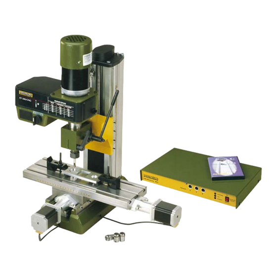
Page 8: View Of The Machine With Its Elements
3. View of the machine with its elements t e r ia l r k z r c h Ø s s e S t a 4 - 1 - 2 0 A lu m in - 3 0 iu m - 4 0 t s t o f f... -
Page 9: Cnc Control Mcs With Operating Elements
4. CNC control MCS with operating elements Fig. 2: Front side Handwheel plug connections Status indicator "Emergency Stop" lock switch Fig. 3: Rear USB connection (for programming the Connection sockets for controller hardware) Mains Connection for the stepping motor connection communications plugs cable to PC... -
Page 10: Technical Data
5. Technical data 5.1. Milling machine: Voltage: 220 - 240 Volt, 50/60 Hz Capacity: 400 Watt spindle speeds 180, 350, 550, 800, 1,300 and 2,500/min shifting the belt: Basic dimensions see Fig. 2 Quill feed: 30 mm using drilling lever with scale ring (1 graduation line = 1 mm). -
Page 11: Drives Of The Tool Axes
5.2. Drives of the tool axes Spindle drive X axis Recirculating ball screw with 4 mm pitch, effective (Longitudinal drive, cross table): diameter 12 mm. Stepping motor 2.2 A, holding torque 1.27 Nm, traverse path: approx. 290 mm Spindle drive Y axis Recirculating ball screw with 4 mm pitch, effective (Transverse drive, lower carriage): diameter 12 mm. -
Page 12: Further Data
5.4. Further data Ambient conditions: 5 - 40°C (Class 3K3), max.60% relative humidity User group Persons as of 14 years of age 5.5. Milling cutter dimensions 6. Scope of delivery 1 Qty. Milling cutter with attached stepping motors 1 Qty. CNC control unit MCS 1 Qty. -
Page 13: Basic Tips On Setting Up And Installing The Machine
7. Basic tips on setting up and installing the machine 7.1. Unpacking and setting up the machine Caution! Do not insert the mains plug before completing the assembly work as the machine could be switched on unintentionally. Risk of injuries! Carefully unpack the individual components from the Styrofoam packaging. - Page 14 Please note: At delivery, some of the blank metal parts of the machine are conserved with corrosion protection. This protection is not intended as lubrication but only as conservation and must be removed before first use, such as with a lint-free cloth saturated with petroleum.
-
Page 15: Connecting The Cabling
7.2. Connecting the cabling How to connect the devices to each other is illustrated in the schematic sketch. Caution! Connect the mains cable to the CNC control MCS and to your computer at the very last and make sure the mains switch at the rear of the CNC control is set to "O", meaning switched off! Do not in any case switch on any electrical device, be it the computer, the CNC control, or the machine itself before the connection of the cables is completed! -
Page 16: Additional Connection Options
7.3. Additional connection options Several additional functions electronically actuated upon request, such as a coolant pump, working light, or similar. The inside of the control has centre-zero relays whose connections can be executed through the 25-pin socket at the rear of the control. Each relay has three pins that are identified by the letters A, R and G. -
Page 17: Installing The Software
8. Installing the software 8.1. Minimum hardware requirements The NCCAD software is very comprehensive and powerful, therefore there are certain minimum requirements towards the utilised control computer: Simple operation and controller PC: • Windows 98/2000/XP • RAM: at least 16 MB •... -
Page 18: Starting The Software Nccad7.5
Windows Explorer. Caution! The values stored there are especially adapted to operation with the FF 500 CNC and should not be changed without experience and knowledge of the program. No changes may be made here especially before commissioning! False entries can lead to system errors and dangerous operating states! 8.5. -
Page 19: Emergency Stop / Lock
8.6. EMERGENCY stop / lock The EMERGENCY stop is used to lock the CNC milling machine for command receipt and for command execution. Only the red status lamp will light up in the "Lock" (Sperren) position. The lock can be useful, for example, to prevent the execution of a movement command that was entered unintentionally. -
Page 20: The Program Nccad 7.5 Milling
9. The program nccad 7.5 milling The program nccad 7.5 generates the control program from the work piece geometry data, co-ordinates communications with the interface control computer/CNC control, the CNC axes, the generation of the step pulses, etc. etc. The control "translates" the signals into commands stepping... -
Page 21: The Structure Of The "Help Topics" Window
9.2. The structure of the "Help topics" window You will find an orientation window on the left with a few tools to help you quickly find what you want to know and which offers you three different search methods. The actual help text appears on the right. -
Page 22: Explanation Of The Icons And The Status Bar
In case of malfunctions that cannot be handled despite thorough perusal of this manual as well as the utilisation of the help system, we would be happy to help you directly. Simply write an e-mail to the address technik@proxxon.com. You will receive a response latest within 3 working days. 22 of 55... -
Page 23: Important Note For Working In Practice
10. Important note for working in practice 10.1. Simple stopping of the machine and the Emergency-Off switch Press any key of the PC keyboard to stop the carriage movement and to switch off the milling machine. The system will then wait for further commands. This "Keyboard Stop"... -
Page 24: First Steps
11. First steps At this point we would like to reiterate that all steps relevant commissioning machine are found in the "Help" function of the program and it is vital to familiarize oneself with these functions before the commissioning. The figure right illustrates... -
Page 25: Semi-Automatic Operation: Traversing The Cnc Axes With The Cursor Keys
If an error message appears instead of the "Manual control" window, the interface may be incorrectly set. To remove the error, it is usually sufficient to readjust the interface in the "Parameters" menu. First click "Machine" and then "Edit parameters". The window shown in the figure on the right appears. -
Page 26: Working With The Milling Cutter
12. Working with the milling cutter 12.1. General information for working with milling cutter Caution! Disconnect the mains plug before you do any adjustments or when exchanging tools! Caution! Please note that despite all the advantages for use in machine tools, the condenser motor used here can become quite warm due to the construction type. -
Page 27: Working With The Drilling Lever
12.2. Working with the drilling lever Please note: Never actuate the drilling lever during CNC operation or even adjust it to a new position! This could cause damage to the machine and/or the work piece! While the milling cutter is operating, the milling head is traversed automatically with the milling spindle, making the use of the drilling lever superfluous: The drilling movements are performed with the Z axis. -
Page 28: Swivelling The Milling Head By Its Own Transverse Axis
Please note: In addition to the supplied collet chucks, we have further sizes available in our accessories range. Please contact our Customer Service should you have any further questions. You will find the postal address at the back of these instructions, or simply write us an e-mail to technik@proxxon.com. 28 of 55... - Page 29 r c h Release swivel nut 4 at the Ø s s e S t a 4 - 1 milling spindle 1. - 2 0 A l u - 3 0 n i u Put the desired collet chuck - 4 0 t s t o f f 5 (see bottom image) by...
-
Page 30: Changing The Spindle Speed
12.5. Changing the spindle speed Setting the spindle speed is necessary so that the cutting speed of the tool can be adapted to the characteristics of the material to be machined and to the tool geometry. Large tool diameters at equal rotational speed also mean a large circumferential speed and thus potentially a too large cutting speed. - Page 31 Caution! Before working on the belt drive, always disconnect the plug from the power socket! Risk of injuries! 1. Release knurled screw 1 and swing up the housing cover. 2. Slightly release fastening screws 4 (small detail) shift housing somewhat to the right until the lower drive belt relaxes.
-
Page 32: Milling
There are various possibilities available to you: Clamping jaws (e.g. 24 257 from PROXXON) and vices (e.g. 24 255 from PROXXON) are very well suited. The cross section of the groove is shown in the image on the right. -
Page 33: Accessories
Gears with the module m=0.5 can be milled using the tooth form cutters from our accessories program; teeth numbers from 12-54 can be realised. You will find further suitable milling and drilling tools in PROXXON quality from our comprehensive program in specialist shops. They will be able to recommend a suitable PROXXON product for your special application case. -
Page 34: Repair, Cleaning And Maintenance
5°C. A cover to protect from dust and environmental effects is sensible. In case of a major repair, please send the machine back to us. The address is: PROXXON G. m b. H. Zentralservice Im Spanischen 18-24... -
Page 35: Replacing The Drive Belt
14.2. Replacing the drive belt If the drive belts are worn, you can replace them yourself. You will receive spare belts from PROXXON Zentralservice (address at the back of these instructions). 1. Release knurled screw 1 and swing up the housing cover. -
Page 36: Adjusting The Play Of The Cross Table Or Z Carriage Guides
14.3. Adjusting the play of the cross table or Z carriage guides If the guide of a cross table or Z carriage axis develops too much play after some time, you can readjust play using adjusting screw 2. To do so, release the counter nuts 1 and evenly turn in all adjusting screws until the play is eliminated. -
Page 37: Cleaning And Care
To properly apply the lubricant, use an oil can or a lint-free cloth saturated with oil or grease. Please, treat the guides and all moving and blank parts in the same manner. Please, also comply with the instructions of the lubricant manufacturers! 14.5. -
Page 38: Disposal
15. Disposal Do not dispose of the device or parts thereof in the household waste! The device contains valuable substances which could be recycled. If you have questions concerning this topic, please address your municipal disposal company or other appropriate municipal institutions. 38 of 55... -
Page 39: Errors And Their Removal
Connecting cable between control is interrupted or not inserted correctly Wrong connecting cable (not the original cable delivered by PROXXON GmbH) Set interface is not available in PC Change to "Manual COM interface for machine and mouse Allocate non-identical control" and then no... - Page 40 Communications Bad connection between PC and CNC error or Time Out machine, COM interface defective Repair Sources of interference exist External sources interference (interfering pulse, EMC-interferences) Utilise original connecting cable (Cable length max. 2m) Work piece zero Machine zero point/reference point is not First remove the causative point is lost approached...
-
Page 41: Compilation Of Safety Notes
17. Compilation of safety notes: As with any other machine, there are some things that need to be observed when operating the CNC milling machine so that dangers to humans and the environment cannot occur. In this context, please also observe the separately enclosed pamphlet with the safety notes. - Page 42 Software safety measures: Locking and stopping the machine: Machining, or movement, can be interrupted at any time (software STOP): • By pressing any key of the alphabetic and numeric keypad or any mouse button. • Activate the switch/pushbutton "Lock" (Sperren) at the CNC control MCS to the "Lock"...
-
Page 43: Ec Declaration Of Conformity
Manufacturer: Proxxon GmbH Im Spanischen D-54518 Niersbach/Eifel, Germany Product designation CNC vertical milling machine Type designation FF 500 CNC Article number 24340 EU Low Voltage Directive 2006/95/EC Applied standards: DIN EN 61029-1 / 12.2003 EU-EMC Directive 2004/108/EC Applied standards: DIN EN 55014-1 / 06.2007... - Page 44 44 of 55...
-
Page 45: List Of Components And Exploded Views
19. List of components and exploded views Please order spare parts in writing from PROXXON Zentralservice (address at the back of these instructions). 19.1. General view 19.1.1 General view exploded drawing and parts list ET No.: Designation 24340 - 01 Assembly group Z axis... - Page 46 r e t l a i Ø t s t f f o 46 of 55...
-
Page 47: Exploded Drawing And Parts List Assembly Group 01:Z Axis
19.1.2 Exploded drawing and parts list Assembly group 01:Z axis ET No.: Designation 24340 - 01 - 01 Z threaded spindle 24340 - 01 - 02 Motor 24340 - 01 - 03 Lid for column 24340 - 01 - 04 Screw 24340 - 01 - 05... - Page 48 48 of 55...
-
Page 49: Exploded Drawing And Parts List Assembly Group 02 Drive Y Axis
19.1.3 Exploded drawing and parts list Assembly group 02 Drive Y axis ET No.: Designation 24340 - 02 - 01 Motor 24340 - 02 - 02 Screw 24340 - 02 - 03 Motor mount Y axis 24340 - 02 - 04 Coupling 24340 - 02 - 05 Nut 24340 -... - Page 50 20 22 21 17 16 18 18 16 4 29 5 30 31 50 of 55...
-
Page 51: Exploded Drawing And Parts List Assembly Group 03 Drive X Axis
19.1.4 Exploded drawing and parts list Assembly group 03 Drive X axis ET No.: Designation 24340 03 - 01 Motor 24340 03 - 02 Screw 24340 03 - 03 Motor mount X axis 24340 03 - 04 Coupling 24340 03 - 05 24340 03 - 06 Ball bearing... - Page 52 52 of 55...
-
Page 53: Exploded Drawing And Parts List Assembly Group 04: Milling Head
19.1.5 Exploded drawing and parts list Assembly group 04: Milling head ET No.: Designation 24340 - 04 - 01 Cover for gearbox 24340 - 04 - 35 Collet chuck 10 mm 24340 - 04 - 02 Rotational speed table 24340 - 04 - 36 Collet chuck 12 mm sticker... - Page 54 Material Stahl Kunststoff – – – – Werkzeug – – – – durchmesse r – – – – Ø mm – – Aluminium – – – – – r e t l a i k r e c r u Ø...
- Page 55 Then please, read through the operating instructions once more. If the device is actually defective, then please send it to: PROXXON Zentralservice D-54518 Niersbach/Eifel, Germany We will respond promptly and reliably! You can also use this address to order any necessary spare parts.
Need help?
Do you have a question about the FF 500 CNC and is the answer not in the manual?
Questions and answers