Table of Contents
Advertisement
Advertisement
Table of Contents

Subscribe to Our Youtube Channel
Related Manuals for Proxxon PD 400 CNC


Summary of Contents for Proxxon PD 400 CNC
- Page 1 Commissioning Manual PD 400 CNC...
- Page 2 Ver. 3.0 03.04.07 2 of 54...
-
Page 3: Table Of Contents
Commissioning Manual PD 400 CNC 1. Some generalities in advance…..................5 2. The technology of your PD 400 CNC at a glance ............6 3. View of the machine with its elements ................8 4. CNC control MCS with operating elements ..............9 5. - Page 4 13.4.4. Parting tools (4)....................28 13.4.5. Threading tools (5)....................28 13.4.6. Inside turning tools (6)..................28 13.5. Inserting the cutting tool in the tool holder ............29 13.6. Clamping in the lathe chuck .................. 30 13.7. Determining the correct spindle speed ..............30 13.8.
-
Page 5: Some Generalities In Advance
Always keep these instructions close to hand. Only operate this device with exact knowledge of it and comply with the instructions. PROXXON will not be liable for the safe function of the device for: handling that does not comply with the usual intended use, other application uses that are not stated in the instructions, disregard of the safety regulations. -
Page 6: The Technology Of Your Pd 400 Cnc At A Glance
2. The technology of your PD 400 CNC at a glance Dear User, With this PD 400 CNC lathe, you have acquired a powerful, precise processing machine that fulfils the highest demands on ease of use, precision and reliability: The mechanical basis is the successful PD 400 lathe from the company PROXXON. - Page 7 2The technology of your PD 400 CNC at a glance If a malfunction occurs despite all these things, the error table at the end of the manual will provide some help. We will also offer direct assistance in case of particularly stubborn cases.
-
Page 8: View Of The Machine With Its Elements
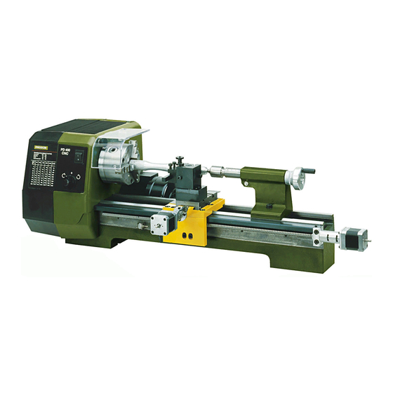
3View of the machine with its elements 3. View of the machine with its elements Main spindle 18 Sleeve adjusting wheel Lathe chuck 19 Clamping screw for sleeve Multiple tool holder 20 Clamping screw for tailstock Gearbox 21 Direction of rotation switch Machine base 22 Operational display Tailstock... -
Page 9: Cnc Control Mcs With Operating Elements
4. CNC control MCS with operating elements Front side: Plug Handwheel Connectors Status indicator "Emergency Stop" locking switch“ Rear: Connection sockets for the plugs Connection for USB connection Mains connection of the stepping motors communications cable to PC Connection for rotary 25-pin plug to control Master switch Connection for... -
Page 10: Technical Data
5Technical data 5. Technical data 5.1. Lathe: Length between centres: 400 mm Height of centres: 85 mm Maximum work piece diameter: 116 mm Machine base: Cross-ribbed surface, high-quality cast iron with ground prismatic guide Spindle: Oversized main spindle, supported with 2 adjustable taper roller bearings Spindle receiver: Spindle drill hole:... -
Page 11: Drives Of The Tool Axes
5Technical data 5.2. Drives of the tool axes Spindle drive Z axis (Leading spindle, longitudinal drive, Recirculating ball screw with 4mm pitch, effective support): diameter 12mm. Stepping motor 1.8A, holding torque 50Ncm Traverse path: 300mm Spindle drive X axis (Transverse drive, support): Recirculating ball screw with 2mm pitch, effective diameter 8mm. -
Page 12: General Data
5Technical data 5.4. General data Ambient conditions: 5 - 40°C (Class 3K3), max.60% relative humidity User group Persons as of 14 years of age 12 of 54... -
Page 13: Scope Of Delivery
6 Scope of delivery 6. Scope of delivery 1 Qty. Lathe with attached stepping motors 1 Qty. CNC control unit MCS 1 Qty. CD with program software (including electronic manual) 1 Qty. Mains cable for CNC control unit MCS 1 Qty. Connecting cable for computer / CNC control unit MCS 1 Qty. -
Page 14: Basic Tips On Setting Up And Assembling The Machine
8 Basic tips on setting up and assembling the machine 8. Basic tips on setting up and assembling the machine The machine may only be set up and operated well- ventilated rooms. The configuration components illustrated schematic figure on the right. -
Page 15: Connecting The Cabling
8 Basic tips on setting up and assembling the machine 8.3. Connecting the cabling Caution! Connect the mains cable to the CNC control MCS at the very last and make sure the mains switch at the rear of the CNC control is set to "O", meaning switched off! Do not in any case switch on any electrical device, be it the computer, the CNC control, or the machine itself before the connection of the cables is completed! The connection sockets on the CNC control are all located at the rear of the housing:... -
Page 16: Additional Connection Options
8 Basic tips on setting up and assembling the machine 8.4. Additional connection options Several additional functions can be electronically driven upon request, such as a coolant pump, working light, or similar. The inside of the control has centre-zero relays whose connections can be executed through the 25-pin socket at the rear of the control. -
Page 17: Installing The Software
9 Installing the software 9. Installing the software 9.3. Minimum hardware requirements The NCCAD software is very comprehensive and powerful, therefore there are certain minimum requirements to the utilised control computer: Simple operation and controller PC: • Windows 98/2000/XP • RAM: at least 16MB •... -
Page 18: Starting The Software Nccad7.5
Windows Explorer. Caution! The values stored there are especially adapted to operation with the PD 400 CNC and should not be changed without experience and knowledge of the program. No changes may be made here especially before commissioning! False entries can lead to system errors and dangerous operating s tates! 9.7. -
Page 19: Emergency Stop / Lock
9 Installing the software 9.8. EMERGENCY stop / lock The EMERGENCY stop is used to lock the CNC machine for command receipt and for command execution. Only the red status lamp will light up in the "Lock" position. The lock can be useful, for example, to prevent the execution of an unintentionally entered movement command. -
Page 20: The Program Nccad 7.5
10 The program nccad 7.5 10. The program nccad 7.5 The program nccad 7.5 generates control program from the work piece geometry data, co- ordinates communications with the interface control computer/CNC control, axes, generation of the step pulses, etc. etc. The control "translates"... -
Page 21: The Structure Of The "Help Topics" Window
10 The program nccad 7.5 been optimised for an intuitive and self-explanatory entry; important things are recognised first and navigation afterwards is effortless: In the normal view, click on Help in the menu line at the top right to start the "Help Function". -
Page 22: Explanation Of The Icons
In case of malfunctions that cannot be handled despite thorough perusal of this manual as well as the utilisation of the help system, we would be happy to help you directly. Simply write an e-mail to the address technik@proxxon.com. You will receive a response within 3 working days. -
Page 23: Important Note For Working In Practice
11 Important note for working in practice 11. Important note for working in practice 11.3. Simple stopping of the machine and the Emergency-Off switch Press any key of the PC keyboard to stop the carriage movement and to switch off the lathe. -
Page 24: First Steps
12 First steps 12. First steps At this point, we would like to reiterate that all steps relevant to commissioning the machine are found in the "Help" function program and it is vital to familiarize oneself with these functions before the commissioning. - Page 25 12 First steps If an error message appears instead of the "Manual control" window, the interface may be incorrectly set. To remove the error, it is usually sufficient to readjust the interface in the "Parameter" menu. First click "Machine" and then "Kosy". The window shown in the figure on the right appears.
-
Page 26: Fundamentals On Working With The Machine
13Fundamentals on working with the machine 13. Fundamentals on working with the machine Caution! Before switching on the machine for the first time, make sure the screws of the lathe chuck are properly tightened, that the key for the lathe chuck is not inserted and that there is sufficient clearance between the support and the lathe chuck. -
Page 27: Fundamentals On Turning And The Pd 400 Cnc Lathe
13 Fundamentals on working with the machine 13.3. Fundamentals on turning and the PD 400 CNC lathe 13.3.1. Straight turning Straight turning is the type of turning whereby the cutter moves on a path parallel to the work piece axis, the "longitudinal feed". -
Page 28: Various Cutting Tools And Their Properties
13 Fundamentals on working with the machine 13.4. Various cutting tools and their properties For various work tasks there are special tools that are optimally co-ordinated to their respective intended use due to their form. The right choice of tool is thus not only essential for the perfect quality of the work result, but some machining can only be done with certain tool forms from the outset. -
Page 29: Inserting The Cutting Tool In The Tool Holder
13 Fundamentals on working with the machine 13.5. Inserting the cutting tool in the tool holder The basic equipment of the PD 400 includes a multiple tool holder consisting of tool holder block 1 and two tool holder elements 2. The tool holder elements can be adjusted in height: Turn the knurled screw 5 up or down until the tool centre is exactly in the centre, meaning at the same height as the work piece axis. -
Page 30: Clamping In The Lathe Chuck
13 Fundamentals on working with the machine 13.6. Clamping in the lathe chuck Caution! Please comply with the enclosed operating instructions of the chuck manufacturer as necessary! Caution! If work pieces are only clamped in the lathe chuck without counter-bracket by the tailstock, the projection may not be greater than the three-fold diameter of the material (L = 3 x D), see figure at right. -
Page 31: Setting The Spindle Speeds By Shifting The Drive Belt
13 Fundamentals on working with the machine 13.8. Setting the spindle speeds by shifting the drive belt The spindle speed can be changed by shifting the motor (multiple contact switch 1 Fig. 4). The speed is halved or doubled. On the other hand, the speed can be changed by shifting the drive belt in the spindle box at the left. -
Page 32: Machining Longer Work Pieces With Tailstock And Lathe Centre
13 Fundamentals on working with the machine 13.9. Machining longer work pieces with tailstock and lathe centre Longer work pieces (chuck projection greater than the 3-fold work piece diameter) must be held at the right end by the tailstock and the travelling lathe centre. To do so, please affix a centring hole on the right side: Carefully face turn the right face side. -
Page 33: Service And Maintenance
14 Service and Maintenance 14. Service and Maintenance Caution! Before doing any maintenance and cleaning work, always switch off the machine with the master switch. Do not use compressed air for cleaning otherwise swarf could get into the guides. In general Therefore, please keep the machine clean and handle with care. -
Page 34: Adjusting The Play Of The Guides
14 Service and Maintenance will thus contribute to a long service life of the guide and a good mechanical condition of the machine. To properly apply the lubricant, use an oil can or a lint-free cloth saturated with oil or grease. - Page 35 5°C. A cover to protect from dust and environmental effects is sensible. In case of a major repair, please send the machine back to us. The address is: PROXXON G. m b. H. Zentralservice Im Spanischen 18-24...
-
Page 36: Disposal
15 Disposal: 15. Disposal: Please do not dispose of the device in the household waste! The device contains valuable substances that can be recycled. If you have any further questions, please contact your municipal disposal company or other appropriate municipal institutions. 36 of 54... -
Page 37: Errors And Their Removal
COM interface set incorrectly CNC machine not switched on Connecting cable between PC and control is interrupted or not inserted correctly Wrong connecting cable (not the original cable delivered by PROXXON GmbH) Set interface is not available in PC 37 of 54... - Page 38 16 Errors and their removal Change to "Manual COM interface for machine and mouse Allocate a non-identical control" and then no are identical interface to both mouse function Mains switch is lit, LEDs are not lit, stepping motors are not humming Internal fuse is interrupted External load of socket "Additional function"...
-
Page 39: Compilation Of Safety Notes
17. Compilation of safety notes As with any other machine, there are some things that need to be observed when operating the CNC lathe PD 400 CNC so that dangers to humans and the environment cannot occur. In this context, please also observe the separately enclosed pamphlet with the safety notes. - Page 40 17Compilation of safety notes Eye and contact protection Wear protective goggles in the immediate vicinity and make sure that the chuck guard is in the correct position when operating the machine. Software safety measures: Locking and stopping the machine: Machining, or movement, can be interrupted at any time (software STOP): By pressing any key of the alphabetic and numeric keypad or any mouse button.
-
Page 41: Ec Declaration Of Conformity
This declaration shall lose its validity if unauthorised changes were made to the system. Manufacturer: Proxxon GmbH Im Spanische n D-54518 Niersbach/Eifel, Germany Product designation CNC Lathe Type designation PD 400 CNC Article number 24500 EU Low-voltage directive 73/23/EWG 93/68/EWG 73/23/EEC 93/68/EEC Angewandte Normen: DIN EN 61029-1 / 12.2003... -
Page 42: List Of Components And Exploded Views
19List of components and exploded views 19. List of components and exploded views Please order spare parts in writing from the PROXXON Central Service (address at the back of the instructions) 42 of 54... -
Page 43: Assembly Group 01 Headstock
19List of components and exploded views 19.1. Assembly group 01 Headstock 43 of 54... - Page 44 19List of components and exploded views ET No.: Designation 24500 - 01 - 01 Gearbox 24500 - 01 - 02 Table thread pitch 24500 - 01 - 03 Placement pad for cover 24500 - 01 - 04 Screw for hinge 24500 - 01 - 05 Screw for gear plate 24500 - 01 - 06...
- Page 45 19List of components and exploded views 24500 - 01 - 46 Ready indicator 24500 - 01 - 47 Screw for chuck guard 24500 - 01 - 48 Chuck guard 24500 - 01 - 49 Placement pad headstock 24500 - 01 - 50 Motor (complete with cover plate) 24500 - 01 - 51 Cover plate for motor...
-
Page 46: Assembly Group 02: Bed With Drive For Z Axis
19List of components and exploded views 19.2. Assembly group 02: Bed with drive for Z axis 46 of 54... - Page 47 19List of components and exploded views ET No.: Designation 24500 - 02 - 01 Bed with ground guide 24500 - 02 - 02 Cover plate 24500 - 02 - 03 Screw for cover plate 24500 - 02 - 04 Screw for motor mounting 24500 - 02 - 05...
-
Page 48: Assembly Group 03: Support With Drive For X Axis
19List of components and exploded views 19.3. Assembly group 03: Support with drive for X axis 48 of 54... - Page 49 19List of components and exploded views ET No.: Designation 24500 - 03 - 01 Screw 24500 - 03 - 02 Motor 24500 - 03 - 03 Coupling 24500 - 03 - 04 Nut 24500 - 03 - 05 Ball bearing 24500 - 03 - 06 Flange 24500 - 03 - 07 Screw 24500 - 03 - 08 Mount...
-
Page 50: Assembly Group 04: Tailstock
19List of components and exploded views 19.4. Assembly group 04: Tailstock ET No.: Designation Travelling lathe centre 28500 - 04 - 01 Sleeve 28500 - 04 - 02 Toggle 28500 - 04 - 03 Washer 28500 - 04 - 04 Threaded pin 28500 - 04 - 05 Screw... - Page 51 19List of components and exploded views 51 of 54...
- Page 52 52 of 54...
- Page 53 Then please read through the operating instructions once more. If the device is actually defective, then please send it to: PROXXON Zentralservice D-54518 Niersbach/Eifel, Germany We will respond promptly and reliably! You can also use this address to order any necessary spare parts.
- Page 54 54 of 54...
Need help?
Do you have a question about the PD 400 CNC and is the answer not in the manual?
Questions and answers