Table of Contents
Advertisement
Quick Links
Advertisement
Table of Contents

Related Manuals for Korg microKONTROL


Summary of Contents for Korg microKONTROL
- Page 1 Owner’s manual...
- Page 2 Be careful not to let metal objects get into the equipment. If something does slip into the equipment, unplug the AC adapter from the wall outlet. Then con- tact your nearest Korg dealer or the store where the equipment was pur- chased.
-
Page 3: Conventions In This Manual
Encoders and keys [ ] of memory to be lost. To safeguard your important data, please save it on Encoders and keys on the microKONTROL’s panel are enclosed in square your computer. Korg will accept no responsibility for any damages resulting brackets [ ]. -
Page 4: Table Of Contents
3. Making controller assignments ..........15 Windows XP users ..............6 4. Saving a scene ................17 ■ Installing the Korg USB-MIDI Driver ........6 5. Managing scene sets on your computer ......18 ■ Uninstalling the Korg USB-MIDI Driver....... 9 ■ Allowing installation of an unsigned driver....... 10 Play mode.............. - Page 5 [12] BEND (Pitch Bend Change message) ........47 [8] PORT (USB-MIDI Port setting)..........36 [13] RPN (RPN message)............48 About the microKONTROL and the driver ports....37 [14] NRPN (NRPN message) ............ 49 MIDI IN devices ..............37 [15] EX (System Exclusive message).......... 50 MIDI OUT devices..............
-
Page 6: Contents Of The Package
RPN MSB/LSB ................ 56 AC adaptor Note no..................56 This supplies power to the microKONTROL. Use the AC adaptor if you will be connecting a MIDI sound module etc. to the microKONTROL via MIDI. Using the Librarian software ........57 (☞p.12 “Making connections and turning the power on”) -
Page 7: Introduction
The microKONTROL can be powered from the USB bus. If the microKONTROL is connected to your computer via USB, it will not require power from the AC adapter. Alternatively, it also gives you the flexibility of running on batteries. -
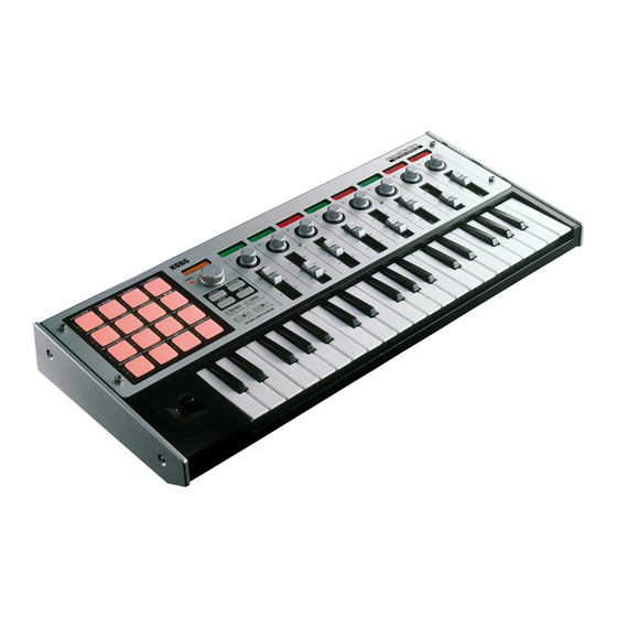
Page 8: Parts And What They Do
Introduction–Parts and what they do Parts and what they do Front panel Trigger pads Main display You can assign control changes or note messages (C-1– In each mode this displays the scene G9) to the trigger pads. name, page, parameters, and other When assigning a control change, you can choose to information. - Page 9 Introduction–Parts and what they do [MESSAGE] key [EXIT] key Sub-displays To enter Message mode, hold down this key Press this key to return to Play mode from These show the names assigned to each and press the trigger pad for the desired Setting, Message, or Scene modes, or to encoder and slider, or the values that are page.
- Page 10 The trigger pads are one of the most useful parts function in each mode. LOCK] key to make it light, and use the pads of the microKONTROL. They’re used for many shown below. different important functions, as described Message mode...
-
Page 11: Rear Panel
Use the AC adapter if you are using the MIDI connectors to control a connected device. If you Use a USB cable to connect the microKONTROL You can connect external MIDI devices to these use a USB cable to connect the microKONTROL... -
Page 12: Driver Installation And Settings
This driver is for Windows XP only. It cannot be used in Windows 95/ 98/Me/2000. Use a USB cable to connect the microKONTROL to your computer, and turn on the power of the microKONTROL. (☞p.12 “Making connections and turning the power on”) - Page 13 Introduction–Driver installation and settings The “USB Audio Device Properties” dialog box will appear. Click the In response to “Please choose your search and installation options”, [Driver] tab, and then click the [Update Driver...] button. you must click “Don’t search. I will choose the driver to install,” and then click [Next>].
- Page 14 CD-ROM drive. Then signed, click [Continue Anyway]. type the name of the folder “D:\Driver” that contains the KORG USB- MIDI driver, and click the [OK] button. The above example is for when your CD-ROM drive is drive “D”. You will need to change this as appropriate for your computer system;...
-
Page 15: Uninstalling The Korg Usb-Midi Driver
From the Control Panel, open [Sounds and Audio Devices], and click the [Hardware] tab. From the list of devices, make sure that microKONTROL is shown for “Location,” and click the [Properties...] button. A dialog box will ask you for confirmation. Click the [OK] button. -
Page 16: Allowing Installation Of An Unsigned Driver
If your computer has been set so that drivers without a digital signature then click [OK]. If necessary, change this setting back to its original cannot be installed, you will not be able to install the Korg USB-MIDI Driver. setting after you have installed the driver. -
Page 17: Mac Os X Users
OS X’s built-in MIDI driver. • One port each of MIDI input and output for external devices For use with Mac OS X, the microKONTROL requires Mac OS X 10.2 or • Two ports of MIDI input from the microKONTROL’s own keyboard and later. -
Page 18: Making Connections And Turning The Power On
If the “BattLow!” warning appears, you can continue using the microKONTROL for a certain length of time, but you will be unable to save Turn on the power of the connected equipment. assignment settings. If you need to save your settings, connect the AC adapter and do so. -
Page 19: Usb Connection
Introduction–Making connections and turning the power on When connecting the AC adapter while running on batteries, you must Set the microKONTROL’s power switch to USB to turn on the power. first connect the AC adapter to an electrical outlet, and then insert the When using a USB connection, the power is supplied from the plug into the microKONTROL’s power connector. -
Page 20: Operation
DAW program you are using on your computer. The scene parameters you set can be stored in the microKONTROL’s internal memory in Scene mode. The stored settings are called a “scene.” Global parameters include the keyboard velocity curve, display backlight, and global MIDI channel. -
Page 21: Quick Start
MIDI channel 2. most effective way. These settings are collectively called a “scene.” The microKONTROL contains twelve preset scenes. Refer to the scene list in the included CD-ROM and select the most suitable scene for controlling your software. The included CD-ROM contains numerous scenes designed for specific software, in addition to the twelve factory-set internal scenes. - Page 22 Operation–Quick Start The OCTAVE SHIFT/CURSOR [√] key will light red, Steps 5-8. Next, press the and the [®] key will light green. Green indicates that OCTAVE SHIFT/CURSOR [√] further pages exist in that direction, and red indicates key to return to the page where that there are no further pages in that direction.
-
Page 23: Saving A Scene
Operation–Quick Start Saving a scene Step 12. Press the OCTAVE SHIFT/CURSOR [®] key. The name select page will appear. If you don’t save your edited controller assignments, your changes will be Since this is the last page of the encoder assignments, lost when you select a different scene or turn off the power. -
Page 24: Managing Scene Sets On Your Computer
Then press the “Save” button to name the scene set and save it as a file. A file you create in this way can be loaded into the microKONTROL whenever needed. -
Page 25: Play Mode
Using the controllers Play mode In Play mode you can use seven types of controllers. In Play mode, you can use the microKONTROL to control connected MIDI 1. Encoders and sliders equipment or soft synthesizers and DAW software on your computer. -
Page 26: Trigger Pads
Operation–Play mode The backlight color of the display will change depending on the controller If a note message is assigned, the pad will light once when the message is you operate. With the default settings, this will be green when you operate a transmitted. -
Page 27: Joystick
Operation–Play mode 3. Joystick When you move the joystick in the X-Y direction If pitch bend or master balance is assigned, the value will be displayed in a When you move the joystick, it will transmit the assigned MIDI message. range of ±24 regardless of the [HEX LOCK] key. -
Page 28: Pedal (Pedal Jack)
Operation–Play mode 4. Pedal (PEDAL jack) 5. Keyboard When you operate a damper pedal or pedal switch connected to the PEDAL When you play the keyboard, note data is transmitted on the global MIDI jack, the assigned MIDI message will be transmitted. channel (☞p.41). -
Page 29: Value] Dial
6. [VALUE] dial This dial adjusts the tempo of the MIDI Clock. If you are synchronizing a connected device or application to the microKONTROL’s MIDI Clock, use the [VALUE] knob to control the tempo. The adjustable range is Clock Off, 020–300. If you select Clock Off, MIDI Clock will not be transmitted. -
Page 30: Setting Mode
In Setting mode you can set both the Scene parameters (the assignment of each controller, etc.) and the Global parameters (overall settings for the If the microKONTROL is operating on batteries and the batteries have entire microKONTROL). run low, you will not be able to save Global parameters. -
Page 31: Encoder (Encoder Assignment)
Operation–Setting mode Press the OCTAVE SHIFT/CURSOR [®] key to proceed to “Message [1] ENCODER (Encoder assignment) Select,” where you can select a MIDI message to assign to the encoder. The Encoder assignment page lets you assign MIDI messages to the rotary (Red) (Green) encoders, specify the MIDI channel on which the messages will be... -
Page 32: Assigning Nrpn Or Rpn
Operation–Setting mode ■ Assigning NRPN or RPN (Green) (Green) If you select NRPN or RPN in “Message Select,” you need to set the “MSB,” “LSB,” and “MIDI Channel” for the message. RPN (Registered Parameter Number) is a type of message used to make settings that are not limited to devices made by a single manufacturer. -
Page 33: Quick-Assign For Control Changes
Operation–Setting mode Use the [VALUE] dial or the pads to input the “LSB” value. The range is 0–127. “LSB” stands for “Least Significant Byte.” Press the OCTAVE SHIFT/CURSOR [®] key to proceed to “MIDI MIDI channel Control change no. Channel.” (Green) (Green) The new control change assignment will be updated when you release... -
Page 34: Pad (Pad Assignment)
Operation–Setting mode Press the OCTAVE SHIFT/CURSOR [®] key to proceed to “Message [3] PAD (PAD assignment) Select” (select the MIDI message). In the PAD assignment page, you can assign MIDI messages to the pads, (Red) (Green) specify the MIDI channel on which the message will be transmitted, and so on. -
Page 35: Pedal (Pedal Assignment)
Operation–Setting mode Press the OCTAVE SHIFT/CURSOR [®] key to proceed to “MIDI Press the [ENTER] key. Channel” (specify the MIDI channel). The settings will be updated and you will return to Play mode. In Play mode, pads to which a control change is assigned will be lit, (Green) (Green) and pads to which a note message is assigned or for which NoAssign is... -
Page 36: Assigning A Control Change
Operation–Setting mode Sostenut (Sostenuto) Press the [ENTER] key. Assigns the Sostenuto message (CC#66) to the pedal. The settings will be updated, and you will return to Play mode. A value of 127 will be transmitted when you press the pedal, and a If you want to keep the new settings, you must save them in Scene value of 0 when you release the pedal. -
Page 37: Joystick-X (Joystick-X Assignment)
Operation–Setting mode Assigning a single MIDI message to the +X and –X Use the [VALUE] dial or the pads to select the MIDI channel on which the MIDI message will be transmitted. The range is 1–16 (ch). (☞p.4 directions “About the trigger pad functions–Input numerical values”) Here’s how to assign a single MIDI message to both left and right directions of the joystick. -
Page 38: Assigning Aftertouch
Operation–Setting mode CtrlChg# (Control Change) Press the OCTAVE SHIFT/CURSOR [®] key to proceed to “Message Select” (select the MIDI message). Assign control change. If you select CtrlChg#, you can also select the control change number. ☞p.33 “Assigning a control change” (Red) (Green) Press the OCTAVE SHIFT/CURSOR [®] key to proceed to “MIDI... -
Page 39: Assigning Velocity
Operation–Setting mode KBD (Keyboard) Use the [VALUE] dial to select the type of aftertouch. The joystick will determine the velocity of notes transmitted by the Ch (Channel AfterTouch) keyboard. The notes are transmitted on the global MIDI channel. Channel Aftertouch. Aftertouch will apply to all the keys that are When you operate the joystick in Play mode, the main display will currently being played. -
Page 40: Assigning Different Midi Messages To The +X And -X Directions
Operation–Setting mode Assigning different MIDI messages to the +X and –X Press the OCTAVE SHIFT/CURSOR [®] key to proceed to “Message Select” (selecting MIDI message). directions Here’s how to assign different MIDI messages to the –X and +X directions of (Green) (Green) the joystick. -
Page 41: Joystick-Y (Joystick-Y Assignment)
Operation–Setting mode Use the [VALUE] dial or the pads to select the MIDI channel on which The assignable content and the assignment procedure are the same as the assigned MIDI message will be transmitted. The range is 1–16 (ch). for the joystick left/right (±X) direction. For details on how to make (☞p.4 “About the trigger pad functions–Input numerical values”) settings, refer to “Joystick-X assignment”... -
Page 42: Port (Usb-Midi Port Setting)
The USB-MIDI Port setting page lets you specify the USB-MIDI transmission Keyboard port that each controller will use when the microKONTROL is connected to Specify the transmission port for the keyboard. a computer via USB. You can specify the transmission port separately for Message each controller. -
Page 43: About The Microkontrol And The Driver Ports
MIDI messages received by the microKONTROL’s MIDI IN connector are MIDI IN connector sent to the computer via this port. If you are using the microKONTROL as a If conventional MIDI messages are received by the microKONTROL, they USB-MIDI interface, select this port in your MIDI software to receive input will be ignored. -
Page 44: Kbd Velocity (Keyboard Velocity Setting)
Operation–Setting mode Since curves 7 and 8 produce less change for medium-strength playing, [9] KBD VELOCITY (Keyboard Velocity setting) they are suitable when you do not need velocity or when you want to make the note strength consistent. However, since there will be greater The Keyboard Velocity setting selects the velocity curve of the keyboard. -
Page 45: Pad Velocity (Pad Velocity Setting)
Operation–Setting mode [10] PAD VELOCITY (PAD Velocity setting) [11] LCD BACKLIG (LCD Backlight setting) The PAD Velocity setting page lets you specify the type of velocity that will The LCD Backlight setting specifies the backlight color of the main display be used when transmitting note messages from the pads. -
Page 46: Pad Illumi (Pad Illumination Setting)
Operation–Setting mode Use the [VALUE] dial to select the backlight color. [13] TRANSPOSE (Transpose setting) Off: backlight off The Transpose setting sets the transposition of the keyboard. Red: red You can adjust this in semitone steps. Grn: green Org: orange Hold down the [SETTING] key and press pad [13]. -
Page 47: Glob.ch (Global Midi Channel Setting)
“–” setting if you have connected a Korg damper pedal (the optional Hold down the [SETTING] key and press pad [14]. DS-1H) or a Korg pedal switch (the optional PS-1). If no pedal is The [SETTING] key and pad [14] will light, and you will be in the connected to the PEDAL jack, select the “–”... -
Page 48: Message Mode
PORT (USB-MIDI Port setting)”) To exit this state, press the [EXIT] key. If you press a pad [9]–[16] to specify and then transmit a message, the microKONTROL will return to Play mode About the OCTAVE SHIFT/CURSOR keys, [ENTER] key, and [EXIT] after the message is transmitted. -
Page 49: Panic (Panic Message)
Operation–Message mode [1] PANIC (Panic message) [2] SNAP (Snap message) This transmits All Note Off [Bn, 7B, 00], All Sound Off [Bn, 78, 00], and This transmits the current values of the encoders and sliders (Snapshot Reset All Controllers [Bn, 79, 00] messages on all MIDI channels. function). -
Page 50: Note Off (All Note Off Message)
Operation–Message mode [3] NOTE OFF (All Note Off message) [5] STOP (Stop message) This transmits an All Note Off [Bn, 7B, 00] message on all MIDI channels. This transmits the realtime message Stop [FC]. Hold down the [MESSAGE] key and press pad [3]. Hold down the [MESSAGE] key and press pad [5]. -
Page 51: Continue (Continue Message)
(specify the value of the message). Pad [8] will briefly go dark, and the main display will indicate the tempo (to the first decimal place) of the timing clock messages the microKONTROL is transmitting. (Red) (Green) Release the [MESSAGE] key to return to Play mode. -
Page 52: Bank (Bank Select Message)
Press the OCTAVE SHIFT/CURSOR [®] key to proceed to “MIDI The next time that you use this function, the previously-specified Channel” (specify the MIDI channel). message will be displayed. The microKONTROL will remember this message until you turn off the power. (Green) -
Page 53: Prog (Program Change Message)
The next time that you use this function, the previously-specified [11] PROG (Program Change message) message will be displayed. The microKONTROL will remember this message until you turn off the power. This lets you transmit a program change message [Cn, mm] (n: channel,... -
Page 54: Rpn (Rpn Message)
If you press the [EXIT] key, the scene number will be displayed. The next time that you use this function, the previously-specified message will be displayed. The microKONTROL will remember this message until you turn off the power. Use the [VALUE] dial or the pads to input the “MSB” value. The range is 0–127. -
Page 55: Nrpn (Nrpn Message)
If you press the [EXIT] key, the scene number will be displayed. The next time that you use this function, the previously-specified message will be displayed. The microKONTROL will remember this message until you turn off the power. Use the [VALUE] dial or the pads to input the Data Entry MSB value. -
Page 56: Ex (System Exclusive Message)
The next time that you use this function, the previously-specified Use the [VALUE] dial or the pads to input 7F, and press the OCTAVE message will be displayed. The microKONTROL will remember this SHIFT/CURSOR [®] key to proceed to the next byte of input. -
Page 57: Free (Free Message)
(Green) You can transmit a message of up to three bytes. Only the status byte of the message you specify will be checked; the microKONTROL will not check whether the message you specify is a valid message. For a single-byte message such as a Realtime message, only the first one or two bytes (depending on the status byte) will be transmitted. -
Page 58: Scene Mode
Operation–Scene mode [1]...[12] Select Scene Scene mode Here’s how to select one of the scenes stored in the microKONTROL’s internal memory. In Scene mode you can select and save scenes, load preset scenes, and transmit and receive dump data. Hold down the [SCENE] key and press the pad of the scene number Scene mode is divided into five pages. -
Page 59: Dump
Use the [VALUE] dial or the pads to select the preset scene that you In the Dump page you can transfer data between the microKONTROL and want to load. If you use the pads, simply press the pad for the scene librarian software running on your computer. -
Page 60: Write
The main display will ask “Sure ?” (“Are you sure you want to write?”) Here you can save the current controller assignments as a scene. You can save twelve different scenes in the microKONTROL’s internal memory. Hold down the [SCENE] key and press pad [16]. -
Page 61: Appendices
038 (26) Data Entry MSB/LSB 007 (07) 039 (27) Channel Volume MSB/LSB 008 (08) 040 (28) Balance MSB/LSB The microKONTROL lets you transmit the following MIDI messages. 009 (09) 041 (29) undefined 010 (0A) 042 (2A) Pan MSB/LSB Channel messages... -
Page 62: Channel Mode Messages
Appendices–Available MIDI messages Note no. CC# (Hex) Function 084 (54) Portamento Control Note (Hex) Note (Hex) Note (Hex) Note (Hex) 085 (55) (00) (24) (48) (6C) undefined C#-1 (01) (25) (49) (6D) 090 (5A) (02) (26) (4A) (6E) 091 (5B) Effect Depth (Reverb Send Level) D#-1 (03) -
Page 63: Using The Librarian Software
Open the installer provided on the CD-ROM, and install the software as directed by the on-screen instructions. The librarian software lets you save and manage the twelve scenes saved in the microKONTROL as a “set” (scene set). The explanatory screens used here are from Mac OS X. Parts and their function Folder tree “Parameter Viewer”... -
Page 64: Saving Scenes On Your Computer
Saving scenes on your computer About the data you can save The following data can be transferred between the Librarian software and Here’s how to save the twelve scenes of the microKONTROL as a Scene Set the microKONTROL. on your computer. -
Page 65: Menu Commands
Redo Re-executes the operation you cancelled by Undo. Deletes the assignment settings of the selected scene. When the microKONTROL finishes receiving the scene data, its main Copy display will indicate “Complete” Copies the assignment settings of the currently selected scene. -
Page 66: Main Shortcut Keys
Save Scene Set As.............. Shift + Command + S Receive Global Data... *Output Parameter ................ Command + D Receives global data from the microKONTROL and saves it as a global Undo ....................Command + Z data file. Redo..................Shift + Command + Z Transmit Global Data... -
Page 67: Midi Implementation
F7: End of exclusive Switching scenes When the microKONTROL receives a message of [F0, 42, 4n, 6E, 00, 1F, 14, ss, F7] (ss=00: Scene number 1 – 0B: Scene number 12), it will switch to the specified scene. When the scene is switched, the microKONTROL will... -
Page 68: About Native Korg Mode
“native mode.” Normally you should exit native mode by using the appropriate menu In this native mode, the microKONTROL can be used as a controller for command in your connected software. If the cable becomes software that specifically supports this mode. -
Page 69: Troubleshooting
■ Connected external device or software does not synchronize Troubleshooting • Could the microKONTROL’s MIDI Clock tempo be set to “Clock Off”? • Check the MIDI Clock settings of the connected device or software. ■ Power does not turn on ■... -
Page 70: Main Specifications
• Sliders × 8 • AC adapter • Pads × 16: velocity-sensitive • USB cable • Joystick: four-way, with switch • CD-ROM (containing microKONTROL Librarian software, scene tem- • [VALUE] dial plates, drivers) • Trigger pad name sheet and labels ■ Display •... -
Page 71: Index
Index Index Backlight ............39 Encoder............. 19 Bank Select message........46 Encoder assignment........25 Battery ...............12 Encoder/Slider Value........52 Battery empty indication........12 [ENTER] key ........3, 24, 42, 52 [EXIT] key......... 3, 24, 42, 52 AC adapter .........1, 5, 12, 13 AfterTouch............32 Channel AfterTouch ........33 All Note Off ............43 Channel message ..........55... - Page 72 Index Polarity..............41 Polarity setting..........41 Joystick ............2, 21 Native Korg mode ...........62 Polyphonic key pressure ........33 Joystick switch assignment......35 Non Registered Parameter Number .....49 PORT ............36, 37 Joystick–X assignment........31 Note no..............56 Portamento ............30 Joystick–Y assignment........35 NRPN ............26, 49 Power supply connector........5...
- Page 73 Index System Exclusive message .......50, 61 System Realtime message ......55 “Save” button ...........57 Windows XP ............6 Installing the Korg USB-MIDI Driver ..6 System setting ..........41 Save..............54 Uninstalling the Korg USB-MIDI Driver .. 9 Computer.............58 WRITE............... 54 Saving a scene ..........17, 54 [SCENE] key............3...
- Page 74 Please also retain your receipt as proof of purchase otherwise your product may be disqualified from the manufacturer’s or distributor’s warranty. KORG INC. 15-12, Shimotakaido 1-chome, Suginami-ku, Tokyo, Japan Printed in China 2003 KORG INC.
Need help?
Do you have a question about the microKONTROL and is the answer not in the manual?
Questions and answers