
Related Manuals for Runco XtremeProjection X-200i


Summary of Contents for Runco XtremeProjection X-200i
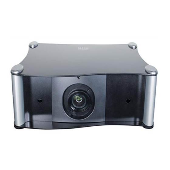
- Page 1 N S T A L L A T I O N P E R A T I O N A N U A L XtremeProjection™ Series X-200i Active 3D Home Theater Projector X-200i X-200i/CineWide X-200i/CineWide with AutoScope...
-
Page 3: Runcocare™ Standard Two Year Limited Warranty
(if any). You may be required to provide proof of purchase in order to receive warranty services. 1. Runco may update this list of products excluded from this warranty from time to time at Runco’s sole discretion, but updates will not apply on a retroactive basis. - Page 4 Once an RMA has been created, RMA status is available at serviceorders@runco.com. • If an RMA is issued, the dealer or customer will need to return the defective product to the Runco repair depot location specified by the Runco technical support representative. The dealer or customer will need to properly package the defective product in a suitable shipping container consisting of the product only, and not include any accessories (e.g., cables,...
- Page 5 Other Terms and Conditions 1. If the defective product is not properly packaged and is damaged in transit during its return to Runco, you may be invoiced for either the repair costs, if repairable, or the MSRP of a replacement product and shipping costs incurred by Runco.
- Page 6 Runco. The trademarks reproduced in this Runco Owner’s Manual and used on the Runco Products are either owned by Runco or are licensed by Runco. You may not reproduce or use the trademarks without the prior written consent of Runco.
-
Page 7: Important Safety Instructions
Important Safety Instructions Thank you for your purchase of this quality Runco video product! For the best performance, please read this manual carefully as it is your guide through the menus and operation. WARNING This symbol is intended to alert the user to the presence of CAUTION uninsulated “dangerous voltage”... - Page 8 The glasses that accompany this product are not safe to use as sunglasses, protective eyewear or any use outdoors or other than only in conjunction with the proper operation of the Runco product with which they are sold. It is common to dim the lights in a home theater. Using 3D glasses and the immersive imagery of stereoscopic imagery can increase the risk of tripping or falling the dark.
-
Page 9: Compliance Information
Council Directive 2006/95/EC and amended by M1 and C1 on Low Voltage Equipment Safety; EN 60950 “Safety of information technology equipment, including electrical business equipment” The Technical Construction file required by this Directive is maintained at the corporate headquarters of Runco International, LLC, located at 1195 NW Compton Drive, Beaverton, OR 97006-1992. - Page 10 The recycling of materials will help to conserve natural resources. This symbol is only valid in the European Union. If you wish to discard this product, please contact your local authorities or dealer and ask for the correct method of disposal. Runco X-200i Series Installation/Operation Manual...
-
Page 11: Table Of Contents
Notes on Batteries ....................13 Notes on Remote Control Operation ..............13 Quick Setup .......................15 Installation Considerations ..................16 Installation Type ....................16 Ambient Light .......................17 Throw Distance.....................17 Vertical and Horizontal Position................19 Lens Shift ......................19 Folded Optics .......................22 Other Considerations ....................22 Runco X-200i Series Installation/Operation Manual... - Page 12 Changing the OSD Language ..................38 Adjusting the Picture Orientation ................39 Rear Projection .....................39 Ceiling Mode......................39 Installing and Adjusting the CineWide Anamorphic Lens ..........39 Cylindrical Anamorphic Lens Installation and Adjustment ........40 Whitney (Prismatic) Anamorphic Lens Installation and Adjustment......45 Runco X-200i Series Installation/Operation Manual...
- Page 13 Command Format ....................81 RS-232 Error Codes .....................91 Using Discrete IR Codes ....................92 IR Command Protocol ..................92 Using HDMI CEC Messages ..................93 CEC Command List....................93 7. Specifications ......................95 X-200i Specifications ....................95 X-200i Dimensions .....................97 Supported Timings .....................98 Runco X-200i Series Installation/Operation Manual xiii...
- Page 14 Table of Contents Notes: Runco X-200i Series Installation/Operation Manual...
- Page 15 4-6. Typical Gray Bar Pattern for Adjusting Contrast ............61 4-7. Typical Test Pattern for Adjusting Sharpness..............62 4-8. X-200i Advanced Image Menu ...................63 4-9. CIE 1931 Color Coordinate Diagram and Effect of PCE Hue and Saturation Controls ........................67 4-10. X-200i System Menu ....................68 Runco X-200i Series Installation/Operation Manual...
- Page 16 List of Figures 4-11. X-200i Service Menu ....................71 6-1. NEC Protocol Message Format ..................92 7-1. X-200i Dimensions .....................97 Runco X-200i Series Installation/Operation Manual...
-
Page 17: Introduction
Target Audience most out of the X-200i. Runco has made every effort to ensure that this manual is accurate as of the date it was printed. However, because of ongoing product improvements and customer feedback, it may require updating from time to time. You can always find the latest version of this and other Runco product manuals on-line, at www.Runco.com. -
Page 18: Using This Manual
Information about obtaining service General information about the XtremeProjection™ Series X-200i Active 3D Home Theater Projector Installation instructions First-time configuration instructions Advanced configuration instructions Troubleshooting tips Specifications for the XtremeProjection™ Series X-200i Active 3D Home Theater Projector Runco X-200i Series Installation/Operation Manual... -
Page 19: Description, Features And Benefits
2.35:1, the image simply gets wider while image height is maintained. With Runco CineWide, the projection system is able to use the full pixel array, thereby producing a 2.35:1 image with enhanced resolution and increased brightness. No resolution or image area is lost to those black bars that contain no picture information. -
Page 20: Key Features And Benefits
Parts List Your X-200i is shipped with the following items. If any items are missing or damaged, please contact your Runco dealer or Runco Customer Service at (800) 23RUNCO. • XtremeProjection™ Series X-200i Active 3D Home Theater Projector • Remote Control Unit and two (2), AA-size batteries •... -
Page 21: Controls And Functions
X-200i at a Glance Projection Lens Focus Ring IR Sensor Exhaust Vent Zoom Control/ Lens Lock IR Sensor Exhaust Vent Vertical Lens Shift Control Horizontal Lens Shift Intake Vent Control Figure 2-1. X-200i Key Functional Components Runco X-200i Series Installation/Operation Manual... - Page 22 Doing so may cause damage to the zoom or lens shift mechanisms. • EXHAUST VENTS Warm air exits the projector through these vents. Ensure that they are not blocked. • INTAKE VENT Internal fans draw cool air into the projector through this vent. Runco X-200i Series Installation/Operation Manual...
-
Page 23: X-200I Rear Panel
3.5-mm, mini phono jack, wired as follows: Ring = No connection Tip = IR Input Sleeve = Ground 5. HDMI 1 (Digital) HDMI 2 (Digital) HDCP-compliant digital video inputs for connecting an HDMI or DVI source. Runco X-200i Series Installation/Operation Manual... - Page 24 Provides an alternative to using the remote control unit to navigate the On-Screen Display (OSD) controls (refer to Controls and Indicators on page 9). 12. 3D SYNC A 3-pin, VESA standard mini-DIN connector for connecting the Active 3D Emitter to the projector (see Figure 3-17). Runco X-200i Series Installation/Operation Manual...
-
Page 25: Controls And Indicators
– Lights solid to indicate that the projector is in standby mode, ready to start. – Flashes (one half-second on/one half-second off) for approximately 90 seconds after the system is turned on (warm-up) or turned off (cool-down). – During normal operation, this LED is off. Runco X-200i Series Installation/Operation Manual... -
Page 26: X-200I Remote Control
Press to select a video source. These buttons are assigned as follows: 1 = HDMI 1; 2 = HDMI 2; 3 = Component 1; 4 = Component 2; 5 = RGB. 8. Contrast Press to adjust white level. Runco X-200i Series Installation/Operation Manual... - Page 27 Press to set the 3D Mode to 3D Side-by-Side. 3D TAB (Top-and-Bottom) Press to set the 3D Mode to 3D Top-and-Bottom. For more information about 3D modes, refer to 3D Mode on Note page 58. 12. LIGHT Press momentarily to activate remote backlighting. Runco X-200i Series Installation/Operation Manual...
-
Page 28: X-200I Active 3D Emitter
Connect the 3D SYNC output from the projector (see Figure 2-2) to this input, using the supplied cable. For more information configuring the emitter to work with the 3D glasses, refer to Using the 3D Glasses on page 73. Runco X-200i Series Installation/Operation Manual... -
Page 29: Installation
Active 3D Emitter. It may help to point the remote directly at the projector during 3D operation. In some cases, it may be better to use the projector keypad when viewing 3D content. Runco X-200i Series Installation/Operation Manual... - Page 30 Installation • The projector’s front IR receivers have a range of approximately 40 feet (12.19 meters). Figure 3-1 shows the reception angles of the IR receivers. Figure 3-1. IR Reception Angles Runco X-200i Series Installation/Operation Manual...
-
Page 31: Quick Setup
Projector calibration: adjust the following for each input; save settings when finished: • Aspect ratio • Brightness • Contrast • Color level • Tint • Input position Prepare Active 3D Glasses for use and test with 3D source mate- rial Runco X-200i Series Installation/Operation Manual... -
Page 32: Installation Considerations
Rear Screen, Floor Mount with Mirror • Projector is completely hidden • Requires separate room • Usually good ambient light rejection • Installation cost is usually higher • Requires less space behind screen than other rear screen installations Runco X-200i Series Installation/Operation Manual... -
Page 33: Ambient Light
Estimating Throw Distance Throw Distance (TD) = Screen Width (w) x Lens Throw Ratio Figure 3-2. Estimating Throw Distance Runco X-200i Series Installation/Operation Manual... - Page 34 AutoScope + 2.40 – 4.00 259.20 432.00 1.80 – 3.00 259.20 432.00 Long-Throw Primary Lens Note: Due to normal manufacturing variances, throw distance can vary by up to +/- 5 percent from these specifications. Runco X-200i Series Installation/Operation Manual...
-
Page 35: Vertical And Horizontal Position
(1.0 x H) Note: This is a general example of lens shift. Lenses vary in their shift capabilities. No particular lens or projector is used in this example. Figure 3-4. Vertical Lens Shift (Example Only) Runco X-200i Series Installation/Operation Manual... -
Page 36: Horizontal Lens Shift (Example Only)
Screen Width (W) Note: This is a general example of lens shift. Lenses vary in their shift capabilities. No particular lens or projector is used in this example. Figure 3-5. Horizontal Lens Shift (Example Only) Runco X-200i Series Installation/Operation Manual... - Page 37 1. Vertical shift limits are percentages of the screen height. Horizontal shift limits are percentages of the screen width. 2. Vertical lens shift figures are for ceiling mount configurations. For floor installations (where the projector is upright), reverse the up/down vertical lens shift percentages. Runco X-200i Series Installation/Operation Manual...
-
Page 38: Folded Optics
• Keep the projector away from devices that radiate electromagnetic energy such as motors and transformers. Common sources of these include slide projectors, speakers, power amplifiers and elevators. Runco X-200i Series Installation/Operation Manual... -
Page 39: Installing The Optional Cinewide Lens Mount
2. Some components shipped with your projector may differ slightly from what is shown in these instructions. Remove Projector Feet: Place the projector upside down on a blanket or other soft surface. Loosen and remove the two front feet on the projector. Runco X-200i Series Installation/Operation Manual... -
Page 40: Installing The Lens Motor (X-200I/Cinewide With Autoscope)
Ceiling Mt. Adapter/ Projector Stand, Right Screw, Phillips Pan-Head, M6-1.0 x 12mm (14x) CineWide with AutoScope Ceiling Mt. Adapter/ Projector Stand, Left AutoScope Lens Motor Figure 3-7. X-200i/CineWide with AutoScope Motor Assembly – Exploded View Runco X-200i Series Installation/Operation Manual... -
Page 41: Connecting The Autoscope Lens Transport Motor To The Projector
AC Input Trigger Input Switch AuptoScope Lens Transport Motor Figure 3-8. Connecting the AutoScope Lens Transport Motor to the Projector After you have installed the AutoScope lens motor, proceed with Mounting the X-200i (page 28). Runco X-200i Series Installation/Operation Manual... -
Page 42: Installing The Fixed Cinewide Base Plate (Prismatic Anamorphic Lens)
M4 x 0.7 x 14mm screws provided with the CineWide lens base plate. See Figure 3-9. DO NOT OVER-TIGHTEN THE SCREWS. Caution Figure 3-9. Projector with Whitney (Prismatic) Lens Base Plate - Bottom View Runco X-200i Series Installation/Operation Manual... -
Page 43: Installing The Fixed Cinewide Base Plate (Cylindrical Anamorphic Lens)
Use only the hardware provided with the CineWide lens base plate. 2. DO NOT OVER-TIGHTEN THE SCREWS. Figure 3-10. X-200i/CineWide with McKinley (Cylindrical) Lens Base Plate and Ceiling Mounting Rails - Bottom View Runco X-200i Series Installation/Operation Manual... -
Page 44: Mounting The X-200I
For a floor installation, turn the adjustable feet at the bottom of the projector to adjust the projection angle. If you do this, you may need to vertically shift the image to compensate. For detailed instructions, refer to Lens Adjustments on page 37. Runco X-200i Series Installation/Operation Manual... -
Page 45: Connections To The X-200I
• Ensure that the cables are securely connected. Tighten the thumbscrews on connectors that have them. To access the connector panel, Connector Panel Access open the rear door by grasping the handle and pulling it down and toward you. Route cables through this opening Runco X-200i Series Installation/Operation Manual... -
Page 46: Connecting Source Components To The X-200I
12V TRIGGER TRIGGER TRIGGER 3D SYNC 3D SYNC HDMI 1 HDMI 2 SYNC SYNC HDMI HDMI COMPONENT 2 COMPONENT HDMI AV OUT HDMI source (BD, DVD, DTV Set-Top Box etc.) Figure 3-11. HDMI/DVI Source Connections Runco X-200i Series Installation/Operation Manual... -
Page 47: Rgb Connection
WIRED WIRED RS-232 RS-232 12V TRIGGER 12V TRIGGER TRIGGER TRIGGER SYNC SYNC HDMI 1 HDMI 1 HDMI 2 HDMI 2 HDMI HDMI HDMI HDMI COMPONENT 2 COMPONENT 2 RGB Camcorder Computer Figure 3-12. RGB Connection Runco X-200i Series Installation/Operation Manual... -
Page 48: Component Video Connections
3D SYNC 3D SYNC HDMI 1 HDMI 1 HDMI 2 HDMI 2 SYNC SYNC HDMI HDMI HDMI HDMI COMPONENT 2 COMPONENT RCA-to-BNC adapter COMPONEN T VIDEO OUT DTV-Set-Top Box (DTV-STB) BD/DVD Figure 3-13. Component Video Connections Runco X-200i Series Installation/Operation Manual... -
Page 49: Controller Connection
WIRED RS-232 2 Receive Data (to ctrl. system) to Automation/ 3 Transmit Data Control System (from ctrl. system) or PC 5 Ground (none of the other pins are used) Figure 3-14. RS-232 Control System Connection Runco X-200i Series Installation/Operation Manual... -
Page 50: Connecting An External Ir Receiver To The Projector
RS-232 RS-232 REMOTE REMOTE WIRED WIRED RS-232 RS-232 12V TRIGGER TRIGGER 3D SYNC 3D SYNC HDMI 1 HDMI 1 HDMI 2 HDMI 2 SYNC SYNC HDMI HDMI HDMI HDMI Figure 3-16. 12-Volt Trigger Output Connection Runco X-200i Series Installation/Operation Manual... -
Page 51: Connecting The Active 3D Emitter To The Projector
Plug the female end of the AC power cord into the AC input on the rear of the lens motor assembly. Connect the other end to your AC power source. Runco X-200i Series Installation/Operation Manual... -
Page 52: Turning On The Power
6. Upon finding a 3D signal, all LEDs turn blue. Once the LEDs indicate a 3D signal, the 3D glasses can be used to experience 3D. For more information on using the Active 3D Glasses, refer to Using the 3D Glasses on page 73. Runco X-200i Series Installation/Operation Manual... -
Page 53: Lens Adjustments
Insert the provided hex wrench into the horizontal lens shift adjuster at the top of the projector. Then, turn the wrench Horizontal to shift the lens in the desired direction. Lens Shift Control Runco X-200i Series Installation/Operation Manual... -
Page 54: Changing The Osd Language
3. Press to highlight Menu Settings, then press ENTER (remote control) or SELECT (system keypad). 4. Press to highlight Language. 5. Press to select a language. Then, press MENU repeatedly to exit the menu system. Runco X-200i Series Installation/Operation Manual... -
Page 55: Adjusting The Picture Orientation
Runco offers two types of anamorphic lenses for its CineWide projectors: prismatic and cylindrical. • The prismatic lens compresses the height of the image (as opposed to stretching the width) to achieve a 2.35:1 aspect ratio with a 1.78:1 display device. -
Page 56: Cylindrical Anamorphic Lens Installation And Adjustment
Lens Installation and Some components shipped with your projector may differ slightly from what is shown in Adjustment these instructions. If any items are missing or damaged, please contact your Runco dealer or Runco Customer Service at (800) 23-RUNCO. Pitch Adjustment... - Page 57 Adapter Ring to the Anamorphic Lens Holder. The Yoke should be as close to the primary lens as possible. 5. Attach the lens to the Lens Adapter Ring by threading it clockwise. Lens threads into ring Figure 3-19. Attaching the Anamorphic Lens to the Lens Ring Runco X-200i Series Installation/Operation Manual...
- Page 58 Too Far Left Correct position Too Far Right 4. When the horizontal position is properly set, tighten the Yaw/X-Adjustment Levers to secure the lens in place. Runco X-200i Series Installation/Operation Manual...
- Page 59 There may be some pincushion distortion even after the lens is Note properly adjusted, especially at shorter throw distances. If this is the case, Runco recommends that you slightly over-scan the image into the screen frame area to mask the distortion. Runco X-200i Series Installation/Operation Manual...
- Page 60 Anamorphic Lens Set Screw (3) to secure the lens in place. (When viewed from the front, the rear opening on the anamorphic lens should appear as a tall, narrow oval.) Focus: Finally, rotate the Focus Ring on the anamorphic lens to fine-tune the optical focus. Runco X-200i Series Installation/Operation Manual...
-
Page 61: Whitney (Prismatic) Anamorphic Lens Installation And Adjustment
3. Secure the lens (with the mounting bracket attached) to the Lens Base Plate (6) using the swell latches. To avoid clipping the corners of the image, position the anamorphic lens as close as possible to the primary lens. Runco X-200i Series Installation/Operation Manual... - Page 62 There may be some pincushion distortion even after the lens is Note properly adjusted, especially at shorter throw distances. If this is the case, Runco recommends that you slightly over-scan the image into the screen frame area to mask the distortion. Runco X-200i Series Installation/Operation Manual...
- Page 63 4. Angle the lens to even out any left-right pincushion distortion: Anamorphic Lens (Top View) Correct Position Wrong Position 5. When the horizontal position and lens angle are properly set, engage the Swell Latches to secure the lens in place. Runco X-200i Series Installation/Operation Manual...
- Page 64 Installation Notes: Runco X-200i Series Installation/Operation Manual...
-
Page 65: Operation
Source Use these buttons on the remote control to select an input source directly, as follows: 1 = HDMI 1 2 = HDMI 2 3 = Component 1 4 = Component 2 5 = RGB Runco X-200i Series Installation/Operation Manual... -
Page 66: Using The On-Screen Menus
6. From the Master Menu, press MENU to turn off the OSD menu. The X-200i OSD menus are arranged hierarchically, as shown in Figure 4-1. Depending on the selected input source and signal characteristics, some menu options may not be available. Runco X-200i Series Installation/Operation Manual... -
Page 67: Advanced Image
Software Version White Balance FPGA Version Reset Everything? Factory Reset (Yes or No) Note: Default settings appear in bold type. Blue Only On or Off Test Patterns On or Off Figure 4-1. X-200i OSD Menu Structure Runco X-200i Series Installation/Operation Manual... -
Page 68: Main
Operation Main The X-200i Main Menu, shown in Figure 4-2, provides access to the most commonly-used projector functions. Figure 4-2. X-200i Main Menu Runco X-200i Series Installation/Operation Manual... - Page 69 16:9 screen. 16:9 4:3 linearly scales the source active image horizontally and vertically to fill a 4:3 rectangle which is centered and the same height as the 16:9 designated image area. The remaining area is black. Runco X-200i Series Installation/Operation Manual...
- Page 70 NON-linear fashion (more on the sides). Virtual- Wide A 4:3 image is horizontally scaled in a NON-linear fashion (more on the sides than in the center) to fit a 16:9 screen. Runco X-200i Series Installation/Operation Manual...
- Page 71 The secondary, anamorphic lens then restores the proper geometry to the 2.35:1 image. A 16:9 image is scaled NON-linearly (more on the sides than in the center) to fit a 2.35:1 Virtual 16:9 screen. Cinema Runco X-200i Series Installation/Operation Manual...
- Page 72 ISF Day or ISF Night memory location. You must enter a passcode to access the Save ISF Note sub-menu. The settings that are saved are the same as those saved with the Save Memory command (see above). Runco X-200i Series Installation/Operation Manual...
- Page 73 Anything outside of the original image area is removed. Figure 4-3 illustrates the effect of each overscan setting for each aspect ratio. Crop Zoom 16:9 = Source Image Area = Edge Noise = Screen (16:9) Figure 4-3. Overscan Examples Runco X-200i Series Installation/Operation Manual...
- Page 74 Use the system keypad on the projector to adjust this setting, so as not to disrupt communication between the Active 3D Emitter and the 3D glasses. Runco X-200i Series Installation/Operation Manual...
-
Page 75: Image
Fine Sync settings (described on page 66) for this timing to the default setting. Use the controls in the Image menu, shown in Figure 4-4, to perform advanced image Image adjustments. Figure 4-4. X-200i Image Menu Runco X-200i Series Installation/Operation Manual... - Page 76 • The dark gray areas are barely visible. • The lighter gray areas are clearly visible. • The white areas are a comfortable level of true white. • The image contains only black, gray and white (no color). Runco X-200i Series Installation/Operation Manual...
- Page 77 Like the Brightness and Contrast controls, the color and tint controls Note are interactive. A change to one may require a subtle change to the other in order to achieve the optimum setting. Runco X-200i Series Installation/Operation Manual...
- Page 78 Main menu and press ENTER. Noise Reduction is useful for clearing up noisy images from interlaced SD sources. Use the button to adjust as desired, keeping in mind that reducing noise (which reduces high frequencies) may also soften the image. Runco X-200i Series Installation/Operation Manual...
-
Page 79: Advanced Image
255,255,255 RGB, assuming an 8-bit image. • RGB-Video uses RGB color space and sets black at 16,16,16 RGB and white at 235,235,235, assuming an 8-bit image, to correspond to the luminance values defined in digital component standards. Runco X-200i Series Installation/Operation Manual... - Page 80 • Auto automatically chooses the appropriate color gamut: • SMPTE C for NTSC, 480i and 480p sources. • EBU for PAL, SECAM, 576i and 576p sources. • REC709 for all other sources. Runco X-200i Series Installation/Operation Manual...
- Page 81 BrilliantColor processing, which improves brightness in grays and secondary colors by using the spoke light from the color wheel. Adaptive Contrast: Adaptive Contrast enhancement expands the light and dark portions of an output image according to the mean luminance of the input image. Runco X-200i Series Installation/Operation Manual...
- Page 82 Steady flickering or several soft vertical stripes or bands across the entire image indicates poor pixel tracking. Proper pixel tracking helps ensure that the image quality is consistent across the screen, that aspect ratio is maintained and that pixel phase (see above) can be optimized. Runco X-200i Series Installation/Operation Manual...
-
Page 83: Cie 1931 Color Coordinate Diagram And Effect Of Pce Hue And Saturation Controls
Saturation adjusts the coordinate's distance from white and Level adjusts the luminance (Y) of the color relative to white. Figure 4-9. CIE 1931 Color Coordinate Diagram and Effect of PCE Hue and Saturation Controls Runco X-200i Series Installation/Operation Manual... -
Page 84: System
X-200i briefly displays an on-screen message confirming your action or briefly describing the error. To prevent the display of these messages, select Message Boxes from the Menu Settings menu to and set it to Off. Runco X-200i Series Installation/Operation Manual... - Page 85 The default is Front Tabletop, for installations where the projector is upright and in fron of the screen. Logo Display: This controls whether or not the Runco logo appears during startup. Altitude: Select Altitude from the System Menu to control the operation of the projector’s cooling fan.
-
Page 86: Control
• For a X-200i with a movable anamorphic lens, choose AutoScope. Auto Source: This control chooses whether or not to scan for other active sources if the current source is not available. The default setting is Off. Runco X-200i Series Installation/Operation Manual... -
Page 87: Service
• Refresh Rate • Lamp Hours (number of lamp hours elapsed since the last reset) Should you ever need to contact Runco Technical Support, this information will help them answer your questions and/or resolve product performance issues. Figure 4-11. X-200i Service Menu... - Page 88 Model Name, Serial Number, installed Software Version and FPGA Version. Should you ever need to contact Runco Technical Support, this information will help them answer your questions and/or resolve product performance issues. Factory Reset: Select Factory Reset from the Service menu to restore all projector settings –...
-
Page 89: Using The 3D Glasses
Operation The 3D LCD Shutter Glasses function with the Runco Active3D Emitter and the projector to provide unsurpassed 3D stereoscopic viewing. This section describes the features, Using the 3D Glasses connection, setup and operation of the 3D LCD Shutter Glasses. -
Page 90: Charging The Battery
The Battery Status LED lights solid red while the battery is charging. When attached to a computer, the Runco Active 3D Glasses use Note the computer only to receive power; the glasses do not appear as a device visible to Windows or any other operating system. -
Page 91: Turning On The Glasses
(the emitter is only active when the projector is in 3D mode) before the five-minute period ends, the glasses stop blinking and remain on. If the glasses automatically turn off, press the Power button to turn them back on. Runco X-200i Series Installation/Operation Manual... - Page 92 Operation Notes: Runco X-200i Series Installation/Operation Manual...
-
Page 93: Maintenance And Troubleshooting
3,000 hours), or sooner if a noticeable degradation in brightness occurs. Contact your Lamp Replacement Runco dealer to obtain a replacement lamp. 1. Turn off the projector and unplug the power cord. Allow the projector to cool down for approximately 60 minutes prior to removing the lamp assembly for replacement. -
Page 94: Troubleshooting Tips
Table 5-1 provides some general guidelines for troubleshooting problems you may encounter with the X-200i. If the suggested solutions fail to resolve the problem or if you Troubleshooting Tips encounter an issue not described here, please contact Runco Technical Support. Table 5-1. Troubleshooting Chart Symptom... - Page 95 Glasses on page 73. with the Active3D Emitter. Note: You can obtain more detailed information about the cause of the error condition using RS-232 commands. Refer to RS-232 Error Codes on page 91 for more information. Runco X-200i Series Installation/Operation Manual...
- Page 96 Maintenance and Troubleshooting Notes: Runco X-200i Series Installation/Operation Manual...
-
Page 97: External Control
The X-200i supports two types of commands: key commands and operation commands. Key commands mimic pressing a button on the remote control. Operation commands tell the projector exactly what to do. All commands start with 2 letters: ky for key commands. op for operations commands. Runco X-200i Series Installation/Operation Manual... - Page 98 Bring up or cancel brightness slider. 0x81 0xC1 Bring up or cancel contrast slider. (none) 0x84 0xC4 Force reacquisition of active source. (none) 0x85 0xC5 Switch to the next gamma. (none) 0x86 0xC6 Switch to 2.5 gamma. Runco X-200i Series Installation/Operation Manual...
- Page 99 Apply 4:3 aspect ratio to the active source. 0xA0 0xE0 Apply Letterbox aspect ratio to the active source. 0xA2 0xE2 Apply VirtualWide aspect ratio to the active source. 0xAF 0xEF Apply Cinema aspect ratio to the active source. Runco X-200i Series Installation/Operation Manual...
- Page 100 Some operations command examples: Input: op bright ? [CR] Response: ACK:BRIGHT = 100 [CR] Input: op bright = 127 [CR] Response: ACK:BRIGHT = 127 [CR] Input: op resync [CR] Response: ACK:RESYNC [CR] Input: op input = 0 [CR] Runco X-200i Series Installation/Operation Manual...
- Page 101 1 = ISF Night brightness 0 - 200 contrast 0 - 200 saturation 0 - 200 0 - 200 sharpness 0 - 200 0 - 200 overscan 0 = Off 1 = Crop 2 = Zoom Runco X-200i Series Installation/Operation Manual...
- Page 102 4 = Native 6 = PCE satco 0 = Off 1 = On red.offset 0-200 green.offset 0-200 blue.offset 0-200 red.gain 0-200 green.gain 0-200 blue.gain 0-200 vert.pos 0-200 horiz.pos 0-200 phase 0-200 tracking 0-200 sync.level 0-200 Runco X-200i Series Installation/Operation Manual...
- Page 103 8 = Yellow 9 = ANSI Checkerboard 10 = Focus Grid altitude 0 = Auto 1 = High status.check 0 = Standby 1 = Powering Up 2 = Displaying 3 = Cooling Down 4 = Error Runco X-200i Series Installation/Operation Manual...
- Page 104 11 = Russian framelock 0 = Off 2D sources only 1 = On 3D.24p.mode 0 = 96Hz 1 = 144Hz 3D.darktime 0 = 1.0 ms 1 = 1.5 ms 2 = 2.0 ms 3 = 2.5 ms Runco X-200i Series Installation/Operation Manual...
- Page 105 Personal Color Equalizer (PCE) white.green.gain white balance settings. white.blue.gain msgbox 0 = On This control enables or disables 1 = Off the display of power off, source and adjustment message boxes (brightness, contrast etc.). Default value is ON. Runco X-200i Series Installation/Operation Manual...
- Page 106 PCE parameters to 100 (50%): hsg = Yellow Level Green Level 646464646464 Cyan Level 646464646464 Blue Level 646464646464 Magenta Level 646464 Red Gain (White Balance) Green Gain (White Balance) (Spaces are for readability.) Blue Gain (White Balance) Runco X-200i Series Installation/Operation Manual...
-
Page 107: Rs-232 Error Codes
PCF8575 external GPIO communication failure. System I2C communication failure. Write EEPROM failure. DDP3021 communication failure upon system power-up. Video board initialization failure. DCF FPGA communication failure upon system power-up. OSD loading error. Scaler (GF9452) is not responding. Runco X-200i Series Installation/Operation Manual... -
Page 108: Using Discrete Ir Codes
Command Byte (logical inverse) 0 0 0 0 0 1 0 0 1 0 0 0 0 0 0 0 1 9 ms 4.5 ms 13.5 ms 27 ms 27 ms Figure 6-1. NEC Protocol Message Format Runco X-200i Series Installation/Operation Manual... -
Page 109: Using Hdmi Cec Messages
Give Physical Address 0x83 None Report Physical Address 0x84 [Physical Address] [Device Type] Request Active Source 0x85 None Set Stream Path 0x86 [Physical Address] Device Vendor ID 0x87 [Vendor ID] Vendor Command 0x89 [Vendor Specific Data] Runco X-200i Series Installation/Operation Manual... - Page 110 Get Menu Language 0x91 None Inactive Source 0x9D [Physical Address] CEC Version 0x9E [CEC Version] Get CEC Version 0x9F None Vendor Command With ID 0xA0 [Vendor ID] [Vendor Specific Data] Abort Message 0xFF None Polling Message None Runco X-200i Series Installation/Operation Manual...
-
Page 111: Specifications
FCC Part 15 Class B, CE Class B, UL, cUL, CB, RoHS, WEEE, local conformances as required 12V Output (2) 3.5mm mini jack Dimensions See Figure 7-1 Lamp Warranty 1000 hours or six (6) months, whichever comes first Weight 60.9 lbs. (27.7kg) Runco X-200i Series Installation/Operation Manual... - Page 112 Specifications Table 7-1. X-200i Specifications (continued) Limited Warranty Projector: (2) Two years parts and labor from the date of shipment from Runco. Extended RuncoCare™, Red Carpet™, and PremierCare™ also available. Processor Dual Stream Vivix™ technology processing Control Options • Discrete infrared (IR) remote •...
-
Page 113: X-200I Dimensions
Specifications Figure 7-1 shows the X-200i dimensions, in millimeters. X-200i Dimensions Figure 7-1. X-200i Dimensions Runco X-200i Series Installation/Operation Manual... -
Page 114: Supported Timings
√ 50.00 56.250 148.500 – – √ 59.94 67.433 148.350 – – √ 60.00 67.500 148.500 – – √ 1080p FP 23.98 26.978 74.175 – – (Frame 1920x1080 √ 24.00 27.000 74.250 – – Packing) Runco X-200i Series Installation/Operation Manual... - Page 115 50.00 28.125/31.250 74.250/72.000 √ √ √ 1080/60i 1920x1080 59.94/60.00 33.716/33.750 74.175/74.250 √ √ √ 1080/24p 1920x1080 23.98/24.00 26.978/27.000 74.175/74.250 √ √ √ 1080/50p 1920x1080 50.00 56.250 148.500 √ √ √ 1080/60p 1920x1080 59.94/60.00 67.433/67.500 148.350/148.500 Runco X-200i Series Installation/Operation Manual...
- Page 116 Specifications Notes: Runco X-200i Series Installation/Operation Manual...
- Page 118 020-1200-00 Rev. A September 2012 Runco International • (800) 23RUNCO • Fax (503) 748-8161 • www.runco.com...
Need help?
Do you have a question about the XtremeProjection X-200i and is the answer not in the manual?
Questions and answers