
Subscribe to Our Youtube Channel
Related Manuals for Runco LightStyle LS-12d


Summary of Contents for Runco LightStyle LS-12d
- Page 1 N S T A L L A T I O N P E R A T I O N A N U A L LS-12d Active 3D Home Theater Projection System...
-
Page 3: Runcocare™ Standard Two Year Limited Warranty
(if any). You may be required to provide proof of purchase in order to receive warranty services. 1. Runco may update this list of products excluded from this warranty from time to time at Runco’s sole discretion, but updates will not apply on a retroactive basis. - Page 4 Once an RMA has been created, RMA status is available at serviceorders@runco.com. • If an RMA is issued, the dealer or customer will need to return the defective product to the Runco repair depot location specified by the Runco technical support representative. The dealer or customer will need to properly package the defective product in a suitable shipping container consisting of the product only, and not include any accessories (e.g., cables,...
- Page 5 Other Terms and Conditions 1. If the defective product is not properly packaged and is damaged in transit during its return to Runco, you may be invoiced for either the repair costs, if repairable, or the MSRP of a replacement product and shipping costs incurred by Runco.
- Page 6 Runco. The trademarks reproduced in this Runco Owner’s Manual and used on the Runco Products are either owned by Runco or are licensed by Runco. You may not reproduce or use the trademarks without the prior written consent of Runco.
-
Page 7: Important Safety Instructions
Important Safety Instructions Thank you for your purchase of this quality Runco video product! For the best performance, please read this manual carefully as it is your guide through the menus and operation. WARNING This symbol is intended to alert the user to the presence of CAUTION uninsulated “dangerous voltage”... - Page 8 The glasses that accompany this product are not safe to use as sunglasses, protective eyewear or any use outdoors or other than only in conjunction with the proper operation of the Runco product with which they are sold. It is common to dim the lights in a home theater. Using 3D glasses and the immersive imagery of stereoscopic imagery can increase the risk of tripping or falling the dark.
-
Page 9: Compliance Information
Council Directive 2006/95/EC and amended by M1 and C1 on Low Voltage Equipment Safety; EN 60950 “Safety of information technology equipment, including electrical business equipment” The Technical Construction file required by this Directive is maintained at the corporate headquarters of Runco International, LLC, located at 1195 NW Compton Drive, Beaverton, OR 97006-1992. - Page 10 FCC PART 15: NOTE: This equipment has been tested and found to comply with the limits for a Class B digital device, pursuant to Part 15 of the FCC Rules. These limits are designed to provide reasonable protection against harmful interference in a residential installation.
-
Page 11: Table Of Contents
Table of Contents RuncoCare™ Standard Two Year Limited Warranty ........... iii Important Safety Instructions ..................vii Compliance Information ....................ix 1. Introduction .......................1 About This Manual .......................1 Target Audience .....................1 If You Have Comments About This Manual.............1 Textual and Graphic Conventions ................1 Using This Manual ......................2 Description, Features and Benefits ................3 Key Features and Benefits ..................4... - Page 12 Table of Contents Other Considerations ....................27 Installing the Optional Anamorphic Lens Mount ............28 Package Contents ....................28 Mounting the LS-12d ....................33 Floor Mounting (Upright) ..................33 Ceiling Mounting (Inverted)..................33 Installing the Projector in an Enclosure ..............33 Adjusting the Projection Angle ................34 Mounting the Dimension Digital Controller ..............35 System Interconnections ....................36 Connecting the Dimension Digital Controller to the Projector.........36 Connecting an Audio Processor or Secondary Display Device to the...
- Page 13 Table of Contents Calibration ......................73 Service .........................81 Using the Runco 3D Glasses ..................94 Key Features......................94 Battery Charging....................94 Power Button and Battery Charge Indicator............95 Turning Off the 3D Glasses ...................95 Auto Power-Off.....................95 5. Maintenance and Troubleshooting ................97 Lamp Replacement ....................97 Troubleshooting Tips ....................98 6.
- Page 14 Table of Contents Notes: LightStyle™ LS-12d Installation/Operation Manual...
- Page 15 List of Figures 2-1. LightStyle™ Series LS-12d Active 3D Projection System Block Diagram ......5 2-2. LS-12d Front/Side View ....................6 2-3. LS-12d Rear/Bottom/Top View ..................8 2-4. LS-12d Rear Panel .......................9 2-5. Dimension Digital Controller Front Panel ..............10 2-6. DC-300 Dimension Digital Controller Rear Panel............12 2-7.
- Page 16 List of Figures 4-4. Typical Color Bar Pattern for Adjusting Color Saturation and Tint........65 4-5. Typical Test Pattern for Adjusting Sharpness..............67 4-6. Overscan Modes ......................69 4-7. CIE 1931 Chromaticity Diagram .................74 6-1. NEC Protocol Message Format ................117 7-1. LS-12d Dimensions....................133 LightStyle™...
-
Page 17: Introduction
Target Audience out of the LS-12d. Runco has made every effort to ensure that this manual is accurate as of the date it was printed. However, because of ongoing product improvements and customer feedback, it may require updating from time to time. You can always find the latest version of this and other Runco product manuals on-line, at www.Runco.com. -
Page 18: Using This Manual
Introduction Graphic Conventions: These symbols appear in numerous places throughout the manual, to emphasize points that you must keep in mind to avoid problems with your equipment or injury: TIPS highlight time-saving short cuts and helpful guidelines for using certain features. NOTES emphasize text with unusual importance or special Note significance. -
Page 19: Description, Features And Benefits
Benefits and a wide array of lens options with Runco’s elegant LightStyle chassis design. With the addition of the LS-12d to Runco’s 3D projection offerings, clients now have a variety of exceptional 3D options to choose from based on their individual needs. -
Page 20: Key Features And Benefits
• Eight (8) HDMI Inputs (on Dimension Digital Controller) with HDCP, 3D and Deep Color • CinOptx™ Proteus lens options for stunning sharpness and throw distance flexibility • Bundled with two years of Runco PremierCare™ service program providing on-site calibration and two years of ongoing support from Runco Parts List Your LS-12d is shipped with the following items. -
Page 21: System Overview
System Overview 2. System Overview A LightStyle™ Series LS-12d Active 3D Projection System consists of the following components: • The projector (equipped with dual digital video inputs) with optional anamorphic lens and lens transport assembly. • The DC-300 Dimension Digital Controller™ unit that provides “left-eye” and “right-eye“ video signals and the on-screen display (OSD) menu to the projector. -
Page 22: Projector
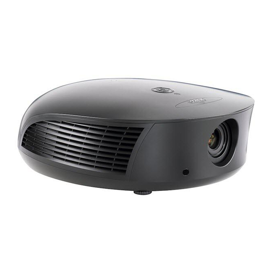
System Overview A LightStyle™ Series LS-12d Active 3D Projection System can display both traditional 2D and stereoscopic 3D video content. Projector An active 3D presentation requires a specialized video signal source configuration and content to be displayed correctly. Images from a stereo 3D video source consist of a series of images (called frames or fields) that alternate quickly between two slightly different view points, corresponding to a viewer’s left and right eyes. - Page 23 System Overview • KEYPAD FOCUS Provides an alternative to using the remote control unit to perform primary lens adjustments (focus, zoom and position). ▲ FOCUS, H/V, ZOOM Use these buttons to select the type of lens adjustment you wish to make. The default function (following a power cycle) is FOCUS.
- Page 24 Opening Ceiling Mount Holes Adjustable Feet Figure 2-3. LS-12d Rear/Bottom/Top View • RUNCO LOGO BADGE • REAR COVER Remove to access connectors. • LAMP MODULE COVER Remove this cover to access the lamp compartment. • CABLE OPENING Pass cables through this opening.
-
Page 25: Ls-12D Rear Panel
7. POWER INPUT (100 to 240 VAC) Connect the LS-12d to power here. 8. 3D Sync Out A 3-pin, VESA standard mini-DIN connector for connecting the Runco Active 3D Emitter to the projector (see Figure 3-21). LightStyle™ LS-12d Installation/Operation Manual... -
Page 26: Dimension Digital Controller
HDMI 1 16:9/1 1080i/60 Figure 2-5. Dimension Digital Controller Front Panel 1. RUNCO ICON Lights blue to indicate that the controller is on or powering up. 2. IR SENSOR Receives IR commands from the remote control. 3. VACUUM FLUORESCENT DISPLAY Can be used instead of the On-Screen Display (OSD). - Page 27 System Overview 6. DOWN BUTTON Use to direct-select aspect ratios or move the menu cursor down in the OSD. When no menu is present on-screen, this button toggles through aspect ratios in the following order: 16:9 - 4:3 - Letterbox - VirtualWide - Cinema - Virtual Cinema - Native 7.
-
Page 28: Rear Panel Layout
1. MAIN POWER SWITCH Disconnects or applies power to the Dimension Digital Controller. 2. 3D Sync Out A 3-pin, VESA standard mini-DIN connector for connecting the Runco Active 3D Emitter to the Dimension Digital Controller. 3. TRIGGERS Connection for up to three (3), 12-volt trigger-controlled devices such as retractable screens or screen masks. - Page 29 System Overview 11. DisplayPort DisplayPort 1.1a and DisplayPort-HDCP 1.1 compliant, SD/HD input for connecting SDTV, EDTV or HDTV component video sources. 12. HD1 / HD2 In (15-pin VGA) Two inputs for connecting standard-definition (SD = 480i/576i), enhanced-definition (ED = 480p/576p) or high-definition (HD = 720p/1080i/1080p) component video sources, or RGBHV sources such as personal computers.
-
Page 30: Ls-12D Remote Control Unit
System Overview Figure 2-7 shows the LS-12d remote control, and the paragraphs that follow describe its functionality. LS-12d Remote Control Unit The LS-12d remote control unit supports an “extended” key code Note mode that allows certain buttons to perform alternate functions. The following list identifies those buttons that have both standard and extended-mode functions. - Page 31 System Overview 1. IR OUTPUT INDICATOR Lights when a button is pressed to indicate that an IR signal is being transmitted. 2. OFF (Standard) / Sleep Timer = 30 Minutes (Extended) Press to turn off the Dimension Digital Controller and projector. In extended mode, press to set the Sleep Timer to 30 minutes.
- Page 32 System Overview 5. Numeric Buttons (Standard) Use these buttons to enter numeric characters (0 ... 9), such as when changing remote control codes (refer to Remote Control on page 83). Numeric Buttons (Extended) In extended mode, press a numbered button to select a video source, as follows: Remote Control Button Source Assignment in Extended Key Code Mode HD 2...
- Page 33 System Overview 10. Cursor Buttons ( , Use these buttons to select items or settings, adjust settings or switch display patterns. When no menu is present on-screen, the UP and DOWN buttons toggle through the available aspect ratios, in this order: UP Button = Native - Virtual Cinema - Cinema - VirtualWide - Letterbox - 4:3 - 16:9 DOWN Button = 16:9 - 4:3 - Letterbox - VirtualWide - Cinema - Virtual Cinema - Native...
- Page 34 System Overview 14. 3D Mode Selection Buttons: 3D AUTO Press to set the 3D Mode to Auto. 3D SBS (Side-by-Side) Press to set the 3D Mode to 3D Side-by-Side. 3D TAB (Top-and-Bottom) Press to set the 3D Mode to 3D Top-and-Bottom. 3D FP (Frame Packing) Press to set the 3D Mode to 3D Frame Packing.
-
Page 35: Installation
Installation 3. Installation Installation must be performed by a qualified custom video Note installation specialist. To install batteries in the remote control: Remote Control 1. Press down the tab on the cover and pull the cover in the direction of the arrow. 2. -
Page 36: Quick Setup
• Aspect ratio • Color level • Brightness • Tint • Contrast • Input position • Color temperature and white balance Prepare Runco Active 3D Glasses for use and test with 3D source material LightStyle™ LS-12d Installation/Operation Manual... -
Page 37: Installation Considerations
Installation Proper installation of your projector will ensure the quality of your display. Whether you are installing a projector temporarily or permanently, you should take the following into Installation account to ensure your projector performs optimally. Considerations It is a common practice in custom audio/video installations to conceal cables by running Pre-Wiring for 3D: Run them through walls. -
Page 38: Throw Distance
Installation Throw Distance Throw distance is the distance measured from the front of the projector to the screen. This is an important calculation in any projector installation as it determines whether or not you have enough room to install your projector with a desired screen size and if your image will be the right size for your screen. -
Page 39: Vertical And Horizontal Position
Anamorphic Lens Minimum Maximum Minimum Maximum For rear-screen installa- tions only. Contact Not Applicable Proteus 1 0.77 (Fixed) Runco Technical Support (Note 2) for more information. Proteus 2 1.45 - 1.74 169.65 203.58 1.09 - 1.30 170.04 202.80 Proteus 3 1.74 - 2.17... -
Page 40: Vertical And Horizontal Lens Shift
Installation Ceiling Installation Ceiling Height Projection Distance Lens Center Lens Center Screen Floor Installation Screen Height Lens Center Lens Center Projection Distance Floor Figure 3-2. Projector Placement Vertical and Horizontal You can use the lens shift controls to center the image on the screen. Lens shift is Lens Shift generally expressed as a percentage of the screen height or width, as shown in Figure 3-3 and Figure 3-4. -
Page 41: Horizontal Lens Shift (Example Only)
Installation 100% Width Lens Shift (1.0 x W) 50% Width Lens Shift (0.5 x W) Screen Center Screen Width (W) Note: This is a general example of lens shift. Lenses vary in their shift capabilities. No particular lens or projector is used in this example. Figure 3-4. -
Page 42: Folded Optics
Installation Folded Optics In rear-screen applications where space behind the projector is limited, a mirror may be used to fold the optical path, as shown in Figure 3-5. The position of the projector and mirror must be accurately set. If you are considering this type of installation, contact your dealer for assistance. -
Page 43: Audio/Video Synchronization Issues
Controller may distribute video signals with a perceptible level of audio latency. In order to Synchronization Issues easily solve this issue, Runco recommends using the Dimension Digital Controller with a high-quality audio receiver that has the ability to effectively synchronize audio and video signals. -
Page 44: Installing The Optional Anamorphic Lens Mount
The LS-12d Anamorphic lens mount kit consists of the following items. Some components shipped with your projector may differ slightly from what is shown in these instructions. If any items are missing or damaged, please contact your Runco dealer or Runco Customer Service at (800) 23RUNCO. - Page 45 Installation Attaching the Transport Assembly Attachment Plate: 1. Place the projector upside down on a blanket or other soft surface. 2. Position the attachment plate as shown here. Attachment Points for Security Hooks Attachment Points for Transport Assembly Attachment Plate and Ceiling Mount Plate 3.
- Page 46 Installation 1. Do not use the mounting screws provided with the ceiling Caution mounting kit. Use only the hardware provided with the Transport Assembly Attachment plate. 2. DO NOT OVER-TIGHTEN THE SCREWS. Attachment Points for Security Hooks Hardware for Attachment Plate and Ceiling Mount Plate (4 Places): Screw, Phillips PH, M4 x 30mm...
- Page 47 Installation Install Transport Pivot Screw Here Hardware for Lens Transport Assembly: Pivot Screw, Pivot Screw, Phillips PH, as assembled #10-32 x 5/8" (1) Nut, #10-32 (1) Attachment Lock Washer, #10-32 (1) Plate Flat Washer, #10-32 (1) Transport Assembly Attachment Points Screw, Phillips PH, Transport Assembly #6-32 x 3/8"...
- Page 48 Installation Attaching the Security Hooks: To help stabilize and support the added weight of the Anamorphic Lens and Lens Transport Assembly, the attachment plate includes two security hooks and related hardware for attaching the front part of the plate to the ceiling above.
-
Page 49: Mounting The Ls-12D
LS-12d and suspend it from the (Inverted) ceiling using a specially-designed ceiling mount fixture. Use only the Runco-approved ceiling mount kit designed for your Note projector. Install the ceiling mount kit according to the instructions provided with it. -
Page 50: Adjusting The Projection Angle
Installation Adjusting the Projection If the LS-12d is ceiling-mounted and the screen is significantly lower than the projector, Angle you can tilt the projector at a slight angle by adjusting the ceiling mount. The projector can be rotated (side-to-side) up to 360 degrees and mounted without it affecting performance. -
Page 51: Mounting The Dimension Digital Controller
Installation The Dimension Digital Controller unit can be placed on any flat, stable surface such as a shelf or table, or it can be rack-mounted using the supplied mounting hardware. Place it in Mounting the a location that provides easy access to the power connectors. Dimension Digital Controller The Dimension Digital Controller unit requires 2U (3.5 inches) or more of vertical rack... -
Page 52: System Interconnections
RJ-11 Male Figure 3-8. RS-232 Connection from the Dimension Digital Controller to the Projector Runco recommends using the RS-232 communication link Note between the LS-12d projector and the Dimension Digital Controller. However, display control using HDMI CEC control messages is also possible. -
Page 53: Connecting The Dimension Digital Controller To The Projector
Installation Figure 3-9 shows how to connect the Dimension Digital Controller to the projector. Dimension Digital Controller Pri. Display Control Sec. Display Control Sec. Display Control 3D SYNC 3D SYNC TRIGGERS TRIGGERS HDMI Out Component / SCART Component / SCART To Sec. -
Page 54: Connecting An Audio Processor Or Secondary Display Device To The
Installation Connecting an Audio The Dimension Digital Controller provides a second HDMI output (labeled HDMI Out Processor or Secondary (Audio Only)) for connection to an audio receiver/switching system or secondary display Display Device to the device for monitoring purposes. See Figure 3-10. Dimension Digital Controller (Optional) The Dimension Digital Controller does not transmit HDMI CEC... -
Page 55: Additional Connections To The Dimension Digital Controller (Optional)
Installation The Dimension Digital Controller provides the following interfaces to external equipment Additional Connections to that allow it to control or be controlled by that equipment: the Dimension Digital Controller (Optional) • An RS-232 interface to a PC or control/automation system; •... -
Page 56: Connecting 12-Volt Trigger Outputs
Installation Connecting 12-volt Trigger Outputs to External Equipment: If your LS-12d is equipped with an anamorphic lens, connect the +12V Trigger Input on the lens transport to a 12-volt trigger output on the Dimension Digital Controller; see Figure 3-12. Similarly connect other 12-volt trigger-activated equipment (such as retractable screens or screen masks) to the other trigger outputs. -
Page 57: External Ir Receiver Connection
Installation Connecting an External IR Receiver to the Dimension Digital Controller: If infrared signals from the remote control cannot reach the Dimension Digital Controller due to excessive distance or obstructions such as walls or cabinet doors, you can connect an external IR receiver to extend the range of the remote control. -
Page 58: Ethernet Network Connection To Dimension Digital Controller
Installation Ethernet Network Connection: Use a standard, Category 5 network cable with an RJ-45 plug to connect a network hub, router or gateway to the Ethernet port on the Dimension Digital Controller; see Figure 3-14. Control Control Sec. Display Control Sec. -
Page 59: Connecting Source Components To The Dimension Digital Controller
Installation Connect your video sources to the Dimension Digital Controller as shown and described Connecting Source in the sections that follow. Components to the Dimension Digital DisplayPort Source Connection: See Figure 3-15. Controller 3D SYNC 3D SYNC TRIGGERS TRIGGERS RS-232 RS-232 To Accessory To Accessory... -
Page 60: Hdmi Source Connections
Installation HDMI Source Connections: See Figure 3-16. Use the HDMI inputs whenever possible. This ensures the highest video quality because the signal is carried in the digital domain throughout the entire signal path, from source component output into the projector. You can also connect computers with DVI output to these inputs. -
Page 61: Component Video Source Connections
Installation Component Video Source Connections: Connect your component video sources to the HD1, HD2 and/or Component/SCART inputs as shown in Figure 3-17. TRIGGERS TRIGGERS 3D SYNC 3D SYNC RS-232 RS-232 To Accessory Box To Accessory Box Component / SCART HDMI 1 HDMI 1 HDMI 3 HDMI 3... -
Page 62: Rgbhv Source Connections
Installation RGBHV Source Connections: Connect personal computers and/or other RGB sources to the HD1 and/or HD2 inputs as shown in Figure 3-18. TRIGGERS TRIGGERS 3D SYNC 3D SYNC Component / SCART Component / SCART Video 1 Video 1 Video 2 Video 2 Video 3 Video 3... -
Page 63: Scart Rgbs Source Connections
Installation SCART RGBS Source Connections: Connect the green, blue and red outputs from your SCART source to the Component/SCART input on the Dimension Digital Controller. Connect the sync output from your SCART source to the Video 1 input on the Dimension Digital Controller. -
Page 64: Composite Video Source Connections
Installation Composite Source Connections: See Figure 3-20. TRIGGERS TRIGGERS 3D SYNC 3D SYNC Component / SCART HDMI 1 HDMI 1 Video 1 Video 2 Video 3 DisplayPor DisplayPor HDMI 2 HDMI 2 Composite Camcorder Composite Composite Gaming Console Figure 3-20. Composite Video Source Connections LightStyle™... -
Page 65: Connecting The Active 3D Emitter To The Projector
Installation Connect the 3D SYNC Out port on the emitter to the 3D Sync Out connector on the Connecting the Active 3D projector, as shown in Figure 3-21. Mount the emitter in a location that provides a clear Emitter to the Projector line of sight between it and the viewing area. -
Page 66: Turning On The Power
6. Upon finding a 3D signal, all LEDs will turn green. 3D Sync Signal Found Once the LEDs indicate a 3D signal, the Runco 3D glasses can be used to experience 3D. For more information on using the Runco Active 3D Glasses, refer to Using the Runco 3D Glasses on page 94. -
Page 67: Primary Lens Adjustments: Focus, Zoom And Position
Installation Lens zoom, focus and position are motorized adjustments that are adjustable using the remote control (Figure 2-7). This allows you to adjust the focus and image size while at the Primary Lens screen for more accurate results. Adjustments: Focus, Zoom and Position If you prefer, you can also perform lens adjustments from the Note... -
Page 68: Adjusting The Image Geometry
Installation 3.11 Projector and/or screen placement — among other things — can cause geometric distortion in the projected image. Adjusting the Image Geometry To correct this, the Dimension Digital Controller provides precise, nine-point control over the projected image geometry. Use these controls as (and only if) needed to re-position the image corners, mid-points and center to eliminate “keystoning”... -
Page 69: Image Alignment Controls
Installation “Keystoning” usually occurs when the projector is tilted relative to the screen. “Pincushion” distortion can sometimes occur if the throw distance is very short and/or the projector is equipped with an anamorphic lens. To correct keystoning or pincushion distortion: 1. -
Page 70: Installing And Adjusting The Anamorphic Lens
Installation 3.12 If you are installing an LS-12d with an anamorphic lens, proceed as follows to install and adjust the lens. Installing and Adjusting the Anamorphic Lens It is extremely important that the primary lens is properly Note adjusted before you install the anamorphic lens. Ensure that the image from the primary lens is perfectly centered on the screen. - Page 71 Note properly adjusted, especially at shorter throw distances. If this is the case, Runco recommends that you slightly over-scan the image into the screen frame area to mask the distortion. 3. Adjust the rotation of the Lens Transport Assembly so that the left and right sides of the image are an equal distance from their respective screen borders.
- Page 72 Installation Notes: LightStyle™ LS-12d Installation/Operation Manual...
-
Page 73: Operation
Operation 4. Operation To display the Main Menu, press the MENU button on the remote control or Dimension Digital Controller front panel (Figure 2-5). Using the On-Screen Menus To select a menu item, use the buttons on the remote control or Dimension Digital Controller front panel to highlight it. - Page 74 Auto Check for New Firmware, Auto Perform Auto Firmware Upgrade Service Upgrade, Check for New Firmware Network E-Mail Address, Error Notification, Error Notification to Runco, Periodic Service Notification, Lamp Life E-Mail Notification Notification, Customer Information, E-Mail Calibration Data Remote Network Control On / Off...
-
Page 75: Main Menu
Operation The Main Menu is the starting point for accessing all Dimension Digital Controller Main Menu functions. Runco Video (You must enter a passcode to access the Calibration and Service menus.) Input Source Aspect Ratio Screen Picture Input Position Memory Presets... -
Page 76: Aspect Ratio
Operation Aspect Ratio To change the aspect ratio (size and shape) of the projected image, select Aspect Ratio from the Main Menu and press ENTER. Select the appropriate aspect ratio for your screen size and the type of program material being viewed; refer to Table 4-1. Aspect Ratio 16:9 The currently-selected aspect ratio is indicated by a “... - Page 77 Operation Table 4-1. Aspect Ratio Settings (continued) Remote Aspect Ratio Control Description Letterbox Letterbox mode scales (zooms in on) a 4:3 image linearly (by the same amount on all sides) to fill 4:3 Image on a 16:9 display. 16:9 Display Letterbox is best suited for (Letterbox aspect ratio) viewing LaserDisc movies or...
-
Page 78: Screen
Operation Table 4-1. Aspect Ratio Settings (continued) Remote Aspect Ratio Control Description Virtual Cinema V-CINE A 16:9 image is scaled NON-linearly (more on the sides than in the center) to fit a 2.35:1 16:9 Image on 16:9 Image on 2.35:1 Screen 2.35:1 Screen screen. -
Page 79: Picture
Color obtain optimal picture quality from Runco video display devices. Accordingly, Runco Tint recommends that setup and calibration be performed by an ISF certified installation Sharpness technician. - Page 80 Operation Brightness: On your external test pattern source, select a PLUGE pattern. (PLUGE is an acronym for “Picture Line-Up Generation Equipment.”) Figure 4-2 shows a typical PLUGE pattern. Below Black Above Black Figure 4-2. Typical PLUGE Pattern for Adjusting Brightness PLUGE patterns vary but generally consist of some combination of black, white and gray areas against a black background.
- Page 81 Operation Contrast: On your external test pattern source, select a stepped, gray-bar pattern like the one shown in Figure 4-3. Figure 4-3. Typical Gray Bar Pattern for Adjusting Contrast Select Contrast and press ENTER. Adjust the contrast to a point just below which the white rectangle starts to increase in size.
- Page 82 Operation 5. Press ENTER again to select Configure. 6. Select Diagnostics and press ENTER. 7. Select Blue from the Diagnostics menu, then press ENTER to display only the blue color channel. 8. Press EXIT (or MENU) repeatedly to return to the Main Menu. 9.
- Page 83 Operation Sharpness: “Sharpness” is the amount of high-frequency detail in the image. To adjust sharpness, select Sharpness from the Picture menu and press ENTER. On your external test pattern source, select a pattern like the one shown in Figure 4-5. Adjust as needed, looking for white edges around the transitions from black to gray and differently-sized lines in the “sweep”...
-
Page 84: Input Position
Operation Input Position Use the controls in the Input Position Menu to fine-tune the aspect ratio and image position for the current source. Input Position Left/Right The input position settings are automatically saved for each input Up/Down Note and resolution. Width Height Overscan... - Page 85 Operation Crop Zoom 16:9 = Source Image Area = Edge Noise = Screen (16:9) Figure 4-6. Overscan Modes Phase (RGB, Component or SCART sources): This control adjusts the phase of the pixel sampling clock relative to the incoming signal. Adjust the phase when an RGB, Component or SCART image still shows shimmer or “noise”...
-
Page 86: Memory Presets
Operation Memory Presets For each input, the Dimension Digital Controller lets you save image quality settings as presets that you can recall at a later time. You can create up to four presets per input and display mode (resolution and frame rate). Memory Presets ISF Night The Dimension Digital Controller stores the following display modes in each memory... -
Page 87: 3D Processing
Operation To save the settings for the current input and display mode to the Note ISF Night or ISF Day memory preset, select Save ISF Night or Save ISF Day from the Calibration menu (refer to Save ISF Night/Save ISF Day on page 78). To reset the Custom 1 or Custom 2 memory preset to its factory-default state, select it, press to highlight Reset and press ENTER. -
Page 88: Sleep Timer
Information your Dimension Digital Controller and display device. Signal System Should you ever need to contact Runco Technical Support, this information will help them Network answer your questions or resolve product performance issues. Field Service Manufacturing... -
Page 89: Calibration
Operation Use the Calibration menu to perform advanced picture quality adjustments. This menu Calibration should be used by ISF-certified technicians only. Calibration You must enter a passcode to access the Calibration menu. ISF Settings Note Display Color Input Image Input Color To recall the ISF Night or ISF Day settings, select “ISF Night”... - Page 90 Operation • Color Temp: Select Color Temp from the Display Color - Common Settings menu to adjust the color temperature. Color temperature establishes the “color of gray” by adjusting the 75% white point to various color points. What are “color points?” A “color point” is an x/y coordinate pair that defines a color’s location on the standard CIE chromaticity graph, shown in Figure 4-7.
- Page 91 Operation Table 4-2 lists the x- and y-coordinates for each color temperature preset in “Simple” mode. Table 4-2. Color Temperature Presets and Associated Color Points Associated x/y Values Color Temperature Preset 3200K 0.423 0.404 5500K 0.332 0.348 6500K 0.313 0.329 7500K 0.299 0.315...
- Page 92 Operation Table 4-3 lists the Color Gamut settings and associated x- and y-coordinates for each primary and secondary color component. Table 4-3. x/y Color Gamut Values Color Gamut Settings and Associated x/y Values Primary REC709 SMPTE “C” Color 0.640 0.330 0.635 0.340 0.640...
- Page 93 Operation The Auto Color Enable and Test Pattern Enable checkboxes let you choose what to display on-screen while making these adjustments. These controls work together as follows: Auto Color Enable Test Pattern Enable Description Setting Setting When both boxes are unchecked, the input signal (normal picture) appears on the display.
- Page 94 Settings menu to enable (On) or disable (Off) ConstantContrast in the optical engine. ConstantContrast uses a dynamic iris that modulates light to the DMD based on the actual content of the video material. Runco recommends that you disable ConstantContrast before adjusting Brightness, Contrast or other image settings.
- Page 95 Operation Copy/Paste - Memory Preset: You can copy and paste settings from one memory preset to another. This gives you a convenient starting point for creating a new preset Copy/Paste based on an existing one, to make the calibration process less time-consuming. Memory Preset Aspect Ratio For example, you can use the Copy/Paste Memory Preset feature to:...
- Page 96 “right eye” output images — you may need to address a command to only the Primary or Secondary scaler. To do this, select Adjustment Mode from the Calibration menu and set it to Primary or Secondary. The Main Menu title changes to “Runco Video (Pri.)” or “Runco Video (Sec.)” when you do this.
-
Page 97: Service
Operation • Splash Enable: When you have finished customizing the splash screen, select Splash Enable from the Splash Configure menu. Then, select On and press ENTER. OSD Position: To adjust the position of the OSD, select OSD Position from the Calibration menu and press ENTER. - Page 98 Operation Table 4-4. Test Patterns and Their Suggested Usage (continued) Pattern Suggested Usage Use this pattern when making brightness, contrast or white balance (gain/offset) adjustments. Grey Bars Use this pattern when measuring or adjusting brightness, contrast or white balance (gain/offset). Full White Use this pattern when aligning the output from the projector’s...
- Page 99 Operation Input Names: You can give each input a descriptive name. For example, you may want to change the default input name to the type of source component connected to it: Input Names “VCR,” “DVD,” “Laptop” et cetera. Input names can be up to 12 characters long. Restore C o mp o s i t e Composite 1...
- Page 100 Operation When you change the Remote Code on the Dimension Digital Controller, you must re-program the Dimension Digital Controller remote control to send that same code. To enable “extended” key code mode, you must re-program the Dimension Digital Controller remote control with a special five-digit code reserved for that purpose. To do this: 1.
- Page 101 Operation To change a button assignment, select the corresponding entry in the SRC 1-7 Keys or SRC 8-14 Keys sub-menu. Then, choose the source input you wish to assign to that SRC 1 Key button. Composite 1 Composite 2 Composite 3 Component HD 1 HD 2...
- Page 102 Operation • Display 3D Settings: Select Display 3D Settings from the Display Device - Configure menu to adjust the following timing settings for the projector’s 3D Sync output (see Figure 3-21) to optimize performance of the glasses, emitter and projector, for realistic simulation and 3D images.
- Page 103 Operation • IP Address: Select IP Address from the IP Configuration menu to manually configure the IP Address of the Dimension Digital Controller, as follows: 1. Press to select the first, second, third or fourth byte of the address. 2. Press to set the value of that byte.
- Page 104 “DC-300 Error” or “Display Error” occurs, select Error Notification from the E-Mail Notification menu and set it to On. • Error Notification to Runco: To have the Dimension Digital Controller send an e-mail message to Runco Customer Support when a “DC-300 Error” or “Display Error”...
- Page 105 Operation • Periodic Service Notification: You can have the Dimension Digital Controller send periodic reminders via e-mail to perform regular maintenance tasks. To do this: 1. Select Periodic Service Notification from the E-Mail Notification menu. 2. Highlight Enable and press ENTER. 3.
- Page 106 Operation • Remote Network Control: Select Remote Network Control from the Network menu to enable or disable control of the Dimension Digital Controller via an IP connection (typically using a web browser). Set it to On to allow all incoming remote network connectivity.
- Page 107 Operation Miscellaneous: Select Miscellaneous from the Service menu to set the following options: • Language: Select Language from the Miscellaneous menu and press the up- or down-arrows to select the OSD Language (English, Français, Deutsch, Italiano, Español, Svenska, (Simplified Chinese), (Traditional Chinese), Português, (Russian),...
- Page 108 Operation HDMI: Select HDMI from the Service menu to set the following options affecting communication between HDMI sources, the Dimension Digital Controller and the LS-12d. • HDMI EDID Extension: Extended display identification data (EDID) is a data structure provided by a display device to describe its capabilities to a graphics card. It is what enables a modern personal computer to know what kind of monitor is connected.
- Page 109 Operation • Logo LED: Select Logo LED from the Front Panel Brightness menu to adjust the brightness of the large, illuminated logo on the left side of the display. The range is from 0 (off) to 31. During a firmware upgrade, this LED lights at full brightness Note regardless of the Logo LED setting.
-
Page 110: Using The Runco 3D Glasses
The glases will charge a completely dead battery in less than three hours. You may use the glasses while the battery is being charged. The battery in the Runco 3D glasses is designed to operate approximately 60 hours on a full charge. The glasses consume more power as needed to maximize reliability. As a result, battery life is a function of many factors, including how much interference from 2.4-GHz devices like wireless routers must be compensated. -
Page 111: Power Button And Battery Charge Indicator
Operation The top of the left earpiece of Power Button and Battery Power/Battery Charge the frames contains a button. Charge Indicator Power Button Indicator Inside the left earpiece is a red LED. Battery Charging Connector Press and hold the Power button until the red LED comes on, then release the button. The LED will then blink in a pattern that indicates the battery charge state. - Page 112 Operation Notes: LightStyle™ LS-12d Installation/Operation Manual...
-
Page 113: Maintenance And Troubleshooting
Device -> Configure -> Display Info., in sequence). For lamp or filter replacement, please contact your nearest Runco authorized service center or Runco dealer. Do not attempt to replace the lamp yourself! 1. Turn off the projector and unplug the power cord. -
Page 114: Troubleshooting Tips
Table 5-1 provides some general guidelines for troubleshooting problems you may encounter with the LS-12d. If the suggested solutions fail to resolve the problem or if you Troubleshooting Tips encounter an issue not described here, please contact Runco Technical Support. Table 5-1. Troubleshooting Chart Symptom... - Page 115 Maintenance and Troubleshooting Table 5-1. Troubleshooting Chart (continued) Symptom Possible Cause(s) Solution The display is jittery or • Poor-quality or improperly • Ensure that the source is unstable. connected source. properly connected and of adequate quality for detection. • The horizontal or vertical •...
- Page 116 Maintenance and Troubleshooting Table 5-1. Troubleshooting Chart (continued) Symptom Possible Cause(s) Solution The projector does not turn • The serial connection from • Ensure that the on or respond to user com- the Dimension Digital Pri. Display Control mands. The vacuum fluores- Controller to the display is (RS-232) output from the cent display on the Dimension...
-
Page 117: External Control
Runco products (manufactured prior to September 2011) that include the DHD Controller. Runco recommends using this new protocol, as it is more concise and provides greater control than the old one. However, to maintain backward compatibility with existing automation/control system modules, the legacy Runco serial protocol is also supported. -
Page 118: Response Format
External Control • y is the operand, which can have one of the following values: ? = “Get” operand + = “Increment” operand = = “Set” operand - = “Decrement” operand • z is the value to set for this parameter. It can have one of two formats: •... -
Page 119: Command And Response Examples
External Control Here are some examples of serial commands and their responses: Command and Response Examples Command Command Data Response Power query when (PWR?) [CR] (0;PWR=1) [CR] unit is powered on (PWR=0) [CR] (0;PWR=0) [CR] Set power to 0 (off) Increment bright- (BRT+) [CR] (0;BRT=25) [CR]... - Page 120 External Control Table 6-1. Serial Commands (continued) Command Read/ Inc/ Setting String? Notes Code Write Value Value Aspect Ratio Copy Action will be performed on any setting value Aspect Ratio Paste PCE Red x -100 PCE Red y -100 Aspect Ratio 0 = 4:3 1 = 16:9 2 = Letterbox...
- Page 121 External Control Table 6-1. Serial Commands (continued) Command Read/ Inc/ Setting String? Notes Code Write Value Value Color Space 0 = REC601 1 = REC709 2 = RGB 3 = RGB Video 4 = Auto Image Alignment Center x -100 Image Alignment Center y -100 Contrast...
- Page 122 External Control Table 6-1. Serial Commands (continued) Command Read/ Inc/ Setting String? Notes Code Write Value Value Error Code 0 = None 1 = Display Lamp Overtemp 2 = Display Ballast Overtemp 3 = Display Fan Init Failure 4 = Display Fan 1 Failure 5 = Display Fan 2 Failure 6 = Display Fan 3 Failure 7 = Display Fan 4 Failure...
- Page 123 External Control Table 6-1. Serial Commands (continued) Command Read/ Inc/ Setting String? Notes Code Write Value Value HDMI Audio Format 0 = Combined 1 = HDMI Out (Pri. Display) 2 = HDMI Out (Sec. Display) 3 = HDMI Out (Audio Only) HDMI EDID Extension 1 0 = Off;...
- Page 124 External Control Table 6-1. Serial Commands (continued) Command Read/ Inc/ Setting String? Notes Code Write Value Value Information Firmware Version Input Green Gain Input Green Offset Information Horizontal Frequency Information Input Resolution Information Input FPGA Version information Micro Version Input Source 0 = Composite 1 1 = Composite 2 2 = Composite 3...
- Page 125 External Control Table 6-1. Serial Commands (continued) Command Read/ Inc/ Setting String? Notes Code Write Value Value Information Sync Type 0 = None 1 = Separate 2 = Composite 3 = Sync-on-green Information Vertical Frequency Remote Key 1 = On 2 = Off Remote Key Repeat 3 = Menu...
- Page 126 External Control Table 6-1. Serial Commands (continued) Command Read/ Inc/ Setting String? Notes Code Write Value Value Remote Key Repeat (cont.) 64 = Keypad Menu (used internally) 65 = Power Toggle (used internally) 66 = Enter Key Up (used internally) 67 = SRC 1 68 = SRC 2 69 = SRC 3...
- Page 127 External Control Table 6-1. Serial Commands (continued) Command Read/ Inc/ Setting String? Notes Code Write Value Value Display Serial Number Model Name Memory Preset 0 = ISF Night 1 = ISF Day 2 = Custom 1 3 = Custom 2 Memory Preset Copy Action will be performed on any setting value...
- Page 128 External Control Table 6-1. Serial Commands (continued) Command Read/ Inc/ Setting String? Notes Code Write Value Value Programmable Source Key 0 = Composite 1 [1 ... 14] 1 = Composite 2 2 = Composite 3 3 = Component 4 = HD 1 5 = HD 2 6 = SCART 7 = HDMI 1...
- Page 129 Sidebar Color Blue Sidebar Color Green Screen 0 = Screen 1 1 = Screen 2 Sidebar Color Red Send Errors to Runco 0 = Off; 1 = On Sharpness Offset Sharpness Screen Masking Bottom Screen Masking Test Pattern 0 = Off; 1 = On Enable LightStyle™...
- Page 130 External Control Table 6-1. Serial Commands (continued) Command Read/ Inc/ Setting String? Notes Code Write Value Value Screen Masking Left Screen Masking Test Pattern 0 = Off; 1 = On Mode Enable Screen Masking Right Screen Masking Top Splash Enable 0 = Off;...
- Page 131 External Control Table 6-1. Serial Commands (continued) Command Read/ Inc/ Setting String? Notes Code Write Value Value Trigger 1 16:9 Trigger 1 4:3 Trigger 1 Letterbox Trigger 1 VirtualWide Trigger 1 Cinema Trigger 1 Virtual Cinema Trigger 1 Native Trigger 2 16:9 Trigger 2 4:3 Trigger 2 Letterbox Trigger 2 VirtualWide...
- Page 132 External Control Table 6-1. Serial Commands (continued) Command Read/ Inc/ Setting String? Notes Code Write Value Value Test Pattern Enable 0 = Off; 1 = On Primary Test Pattern 0 = Off; 1 = On Secondary Test Pattern 0 = Off; 1 = On Tracking -100 Image Alignment Top Right x...
-
Page 133: Using Discrete Ir Codes
External Control The Dimension Digital Controller accepts commands in the form of IR signals that conform to the NEC protocol. Each Dimension Digital Controller remote control button has an NEC Using Discrete IR control code associated with it. Codes You can use these codes to program a third-party, “universal” remote control unit to work with the Dimension Digital Controller. -
Page 134: Ir Command List (Standard Mode)
External Control IR Command List Table 6-2 lists the NEC control codes for the Dimension Digital Controller. (Standard Mode) Table 6-2. NEC Control Codes for the Dimension Digital Controller (Standard Mode) Remote NEC Data Control Address Data From Remote Description Button Name (Note) 8209... - Page 135 External Control Table 6-2. NEC Control Codes for the Dimension Digital Controller (Standard Mode) (continued) Remote NEC Data Control Address Data From Remote Description Button Name (Note) Right 8209 0x20111DE2 Right-Arrow ( Down 8209 0x20111EE1 Down-Arrow ( Left 8209 0x20111FE0 Left-Arrow ( ENTER 8209...
- Page 136 External Control Table 6-2. NEC Control Codes for the Dimension Digital Controller (Standard Mode) (continued) Remote NEC Data Control Address Data From Remote Description Button Name (Note) COMP 8209 0x201148B7 Component video input HD 1 8209 0x201149B6 HD1 video input HD 2 8209 0x20114AB5...
-
Page 137: Ir Command List (Extended Mode)
External Control Table 6-3 lists the Extended-mode NEC control codes for the Dimension Digital IR Command List Controller. To use the remote control unit in extended mode, set the address code to (Extended Mode) 88999 (refer to Remote Control on page 83). Table 6-3. -
Page 138: Using Hdmi Cec Messages
External Control The Dimension Digital Controller accepts and can respond to CEC command messages from a disc player, satellite receiver or DVR/set-top box via an HDMI connection. Using Using HDMI CEC CEC, the Dimension Digital Controller can perform the following actions: Messages •... - Page 139 External Control Table 6-4. CEC Commands Supported by the Dimension Digital Controller (continued) Supported? (√ = Yes, – = No) Opcode Value Initiator Follower √ Set Menu Language 0x32 – √ Give Physical Address 0x83 – √ Set Stream Path 0x86 –...
- Page 140 External Control Notes: LightStyle™ LS-12d Installation/Operation Manual...
-
Page 141: Specifications
Picture Size (16:9 Screen): Recommended Width: 80 - 117 in. Maximum Width: 175 in. Processing: Runco Dimension Digital Controller with ViVix IV™ technology and BRiC (Backup, Recovery and Clone) tool Control Options: • Serial commands via RS-232 • Discrete infrared (IR) remote •... - Page 142 Specifications Table 7-1. LS-12d Projector Specifications (continued) Light Output (3D): CSMS Specifications** – Home Theater Calibration: 320 ANSI Lumens; 23 Foot-Lamberts (fL) Uncalibrated: 466 ANSI Lumens **Measured on a 2.0 gain, 84" wide 16:9 screen Contrast Ratio: CSMS Contrast Ratio: >250:1 (ANSI); 10,000:1 full-on, full-off Illumination System: 230W / 260W HPM lamp...
-
Page 143: Dimension Digital Controller Specifications
Parameters: Trigger Outputs: (3) +12 VDC, each rated at 250 mA and thermal fuse-protected Accessory Applications: Runco Firmware Upgrader, Runco BRiC (backup, restore, clone), CalMAN by SpectraCal for automatic calibration Power Requirements: 100-240V~, 47-63Hz, 0.85 Amps Operating Environment: 41°F to 104°F (5°C to 40°C), 0% to 90% humidity (non-condensing);... - Page 144 FCC class B, CE, RoHS, China RoHS, WEEE, C-Tick, CCC, local conformances as required Limited Warranty: Two (2) years parts and labor from the date of shipment from Runco. Specifications are subject to change without notice. LightStyle™ LS-12d Installation/Operation Manual...
-
Page 145: Supported Timings
Specifications Table 7-3 lists the signal types supported by each input on the Dimension Digital Controller. Supported Timings Table 7-3. Supported Signal Timings by Input Supported? (√ = Yes, – = No) Horizontal Refresh Pixel Frequency Format Resolution Frequency Rate (Hz) (MHz) (kHz) Supported 3D Modes... - Page 146 Specifications Table 7-3. Supported Signal Timings by Input (continued) Supported? (√ = Yes, – = No) Horizontal Refresh Pixel Frequency Format Resolution Frequency Rate (Hz) (MHz) (kHz) Supported 3D Modes (continued) √ 23.98 26.978 74.175 – – – – – √...
- Page 147 Specifications Table 7-3. Supported Signal Timings by Input (continued) Supported? (√ = Yes, – = No) Horizontal Refresh Pixel Frequency Format Resolution Frequency Rate (Hz) (MHz) (kHz) Supported 2D Modes (continued) √ √ √ √ 1152x864 1152x864 75.00 67.500 108.000 –...
- Page 148 Specifications Table 7-3. Supported Signal Timings by Input (continued) Supported? (√ = Yes, – = No) Horizontal Refresh Pixel Frequency Format Resolution Frequency Rate (Hz) (MHz) (kHz) Supported 2D Modes (continued) SCART √ – 50.00 – – – – – –...
-
Page 149: Ls-12D Dimensions
Specifications Figure 7-1 shows the LS-12d dimensions, in [millimeters] and inches. LS-12d Dimensions 642.6 25.30 132.0 5.20 REMOVABLE REAR COVER 211.9 8.34 12.8 (ADJUSTABLE) 4X MOUNTING HOLES 194.6 150.0 7.66 5.91 M4-.7 (MAX 10mm WITHOUT FIX PLATE) 99.9 3.93 44.0 2X Ø... - Page 150 Specifications Notes: LightStyle™ LS-12d Installation/Operation Manual...
- Page 152 020-1179-01 Rev. A May 2012 Runco International • (800) 23RUNCO • Fax (503) 748-8161 • www.runco.com...
Need help?
Do you have a question about the LightStyle LS-12d and is the answer not in the manual?
Questions and answers