
Related Manuals for Runco XtremeProjection X-450d


Summary of Contents for Runco XtremeProjection X-450d
- Page 1 N S T A L L A T I O N P E R A T I O N A N U A L XtremeProjection™ Series X-400d and X-450d Active 3D Home Theater Projection System...
-
Page 3: Runcocare™ Standard Two Year Limited Warranty
(if any). You may be required to provide proof of purchase in order to receive warranty services. 1. Runco may update this list of products excluded from this warranty from time to time at Runco’s sole discretion, but updates will not apply on a retroactive basis. - Page 4 Once an RMA has been created, RMA status is available at serviceorders@runco.com. • If an RMA is issued, the dealer or customer will need to return the defective product to the Runco repair depot location specified by the Runco technical support representative. The dealer or customer will need to properly package the defective product in a suitable shipping container consisting of the product only, and not include any accessories (e.g., cables,...
- Page 5 Other Terms and Conditions 1. If the defective product is not properly packaged and is damaged in transit during its return to Runco, you may be invoiced for either the repair costs, if repairable, or the MSRP of a replacement product and shipping costs incurred by Runco.
- Page 6 Runco. The trademarks reproduced in this Runco Owner’s Manual and used on the Runco Products are either owned by Runco or are licensed by Runco. You may not reproduce or use the trademarks without the prior written consent of Runco.
-
Page 7: Important Safety Instructions
Important Safety Instructions Thank you for your purchase of this quality Runco video product! For the best performance, please read this manual carefully as it is your guide through the menus and operation. WARNING This symbol is intended to alert the user to the presence of CAUTION uninsulated “dangerous voltage”... - Page 8 The glasses that accompany this product are not safe to use as sunglasses, protective eyewear or any use outdoors or other than only in conjunction with the proper operation of the Runco product with which they are sold. It is common to dim the lights in a home theater. Using 3D glasses and the immersive imagery of stereoscopic imagery can increase the risk of tripping or falling the dark.
-
Page 9: Compliance Information
Council Directive 2006/95/EC and amended by M1 and C1 on Low Voltage Equipment Safety; EN 60950 “Safety of information technology equipment, including electrical business equipment” The Technical Construction file required by this Directive is maintained at the corporate headquarters of Runco International, LLC, located at 1195 NW Compton Drive, Beaverton, OR 97006-1992. - Page 10 The recycling of materials will help to conserve natural resources. This symbol is only valid in the European Union. If you wish to discard this product, please contact your local authorities or dealer and ask for the correct method of disposal. Runco X-400d/X-450d Installation/Operation Manual...
-
Page 11: Table Of Contents
Front Panel Layout....................8 Rear Panel Layout ....................10 X-400d/X-450d Remote Control Unit .................12 X-400d/X-450d Active 3D Emitter ................16 3. Installation .......................17 Remote Control ......................17 Notes on Batteries ....................17 Notes on Remote Control Operation ..............17 Quick Setup .......................18 Runco X-400d/X-450d Installation/Operation Manual... - Page 12 Additional Connections to the Dimension Digital Controller (Optional)....37 Connecting Source Components to the Dimension Digital Controller ....41 Connecting the Active 3D Emitter to the Dimension Digital Controller....47 Connecting to AC Power ..................47 Turning on the Power ....................48 Runco X-400d/X-450d Installation/Operation Manual...
- Page 13 Information ......................76 Calibration ......................77 Service .........................85 Using the 3D Glasses ....................98 Key Features......................98 Functional Overview....................98 Charging the Battery.....................99 Turning On the Glasses ..................100 Auto Power-Off....................100 5. Maintenance and Troubleshooting ..............101 Lamp Replacement ....................101 Troubleshooting Tips ....................102 Runco X-400d/X-450d Installation/Operation Manual xiii...
- Page 14 IR Command List (Standard Mode) ..............123 IR Command List (Extended Mode) ..............126 Using HDMI CEC Messages ..................127 CEC Command List....................127 7. Specifications ......................129 X-400d/X-450d Projector Specifications ..............129 Dimension Digital Controller Specifications ...............132 Supported Timings ....................134 X-400d/X-450d Dimensions ..................138 Runco X-400d/X-450d Installation/Operation Manual...
- Page 15 3-21. HDMI Source Connections ..................42 3-22. Component Video Source Connections..............43 3-23. RGBHV Source Connections..................44 3-24. SCART RGBS Source Connections................45 3-25. Composite Video Source Connections ..............46 3-26. Active 3D Emitter Connection...................47 3-27. Keystone and Pincushion Distortion .................50 Runco X-400d/X-450d Installation/Operation Manual...
- Page 16 4-4. Typical Color Bar Pattern for Adjusting Color Saturation and Tint........69 4-5. Typical Test Pattern for Adjusting Sharpness..............71 4-6. Overscan Modes ......................73 4-7. CIE 1931 Chromaticity Diagram .................78 6-1. NEC Protocol Message Format ................122 7-1. X-400d/X-450d Dimensions ..................138 Runco X-400d/X-450d Installation/Operation Manual...
-
Page 17: Introduction
Target Audience out of the X-400d/X-450d. Runco has made every effort to ensure that this manual is accurate as of the date it was printed. However, because of ongoing product improvements and customer feedback, it may require updating from time to time. You can always find the latest version of this and other Runco product manuals on-line, at www.Runco.com. -
Page 18: Using This Manual
... Turn to page: Information about obtaining service General information about the X-400d/X-450d Active 3D Projec- tion System Installation instructions First-time configuration instructions Advanced configuration instructions Troubleshooting tips Specifications for the X-400d/X-450d Active 3D Projection Sys- Runco X-400d/X-450d Installation/Operation Manual... -
Page 19: Description, Features And Benefits
3D performance. This 2U outboard controller provides a level of flexibility and control not commonly found in integrated processors, and provides the Runco installer with a full suite of calibration tools necessary to achieve a perfect picture in any viewing environment. -
Page 20: Key Features And Benefits
• Eight (8) HDMI Inputs (on Dimension Digital Controller) with HDCP, 3D and Deep Color • CinOptx™ Proteus lens options for stunning sharpness and throw distance flexibility • Bundled with two years of Runco PremierCare™ service program providing on-site calibration and two years of ongoing support from Runco Parts List Your X-400d/X-450d is shipped with the following items. -
Page 21: System Overview
Scaler Trigger Secondary Video Secondary (Right) Video Scaler Active 3D L/R Stereo Sync Emitter Active 3D Glasses 2D/3D Video Decoder/ HDMI, DisplayPort, Multiplexer Component, SCART, RGB, Composite Figure 2-1. X-400d/X-450d Active 3D Projection System Block Diagram Runco X-400d/X-450d Installation/Operation Manual... -
Page 22: Projector
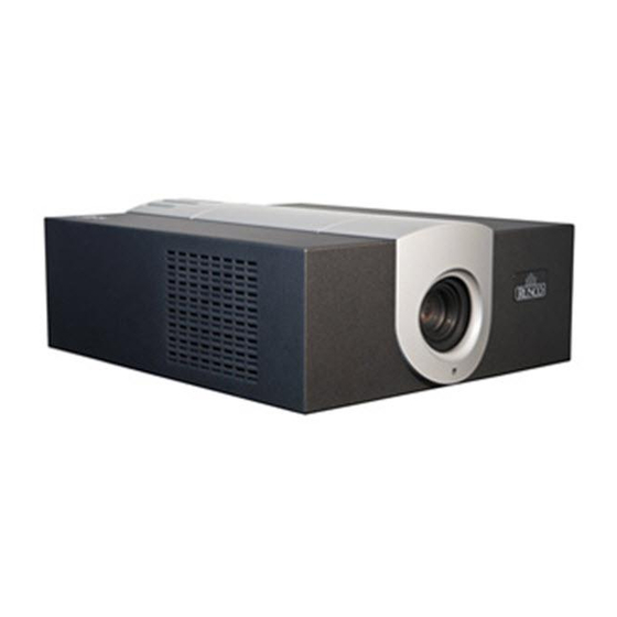
When these frames are displayed fast enough and viewed with special stereo glasses synchronized to the left/right changes, the resulting image appears with the same depth and perspective that is sensed in the real world. Figure 2-2 shows the key X-400d/X-450d components. Figure 2-2. X-400d/X-450d Front/Bottom/Side/Top Views Runco X-400d/X-450d Installation/Operation Manual... -
Page 23: X-400D/X-450D Rear Panel
A female, 9-pin D-sub connector that provides a serial communication link to the Dimension Digital Controller, via its Pri. Display Control output (see Figure 2-5). 2. 3D LED Lights green when the projector is displaying 3D content. Runco X-400d/X-450d Installation/Operation Manual... -
Page 24: Dimension Digital Controller
HDMI 1 16:9/1 1080i/60 Figure 2-4. Dimension Digital Controller Front Panel 1. RUNCO ICON Lights blue to indicate that the controller is on or powering up. 2. IR SENSOR Receives IR commands from the remote control. Runco X-400d/X-450d Installation/Operation Manual... - Page 25 Native - Virtual Cinema - Cinema - VirtualWide - Letterbox - 4:3 - 16:9 10. ENTER BUTTON When an item is highlighted on the OSD, the ENTER button selects the item. 11. STANDBY LED Lights amber when the Dimension Digital Controller is in standby mode; otherwise it is off. Runco X-400d/X-450d Installation/Operation Manual...
-
Page 26: Rear Panel Layout
1. MAIN POWER SWITCH Disconnects or applies power to the Dimension Digital Controller. 2. 3D Sync Out A 3-pin, VESA standard mini-DIN connector for connecting the Runco Active 3D Emitter to the Dimension Digital Controller (see Figure 3-26). 3. TRIGGERS Connection for up to three (3), 12-volt trigger-controlled devices such as retractable screens or screen masks. - Page 27 “HDMI Audio Out” connector. 18. HDMI Out (To Secondary Display) Connect this to the SECONDARY video input on the projector. 19. HDMI Out (To Primary Display) Connect this to the PRIMARY video input on the projector. Runco X-400d/X-450d Installation/Operation Manual...
-
Page 28: X-400D/X-450D Remote Control Unit
The following list identifies those buttons that have both standard and extended-mode functions. For more information, refer to Remote Control on page 87 and IR Command List (Extended Mode) on page 126. Figure 2-6. Dimension Digital Controller Remote Control Unit for X-400d/X-450d Runco X-400d/X-450d Installation/Operation Manual... - Page 29 2.35:1 screen. In extended mode, press to select the Component input. NATIVE (Standard) / HD 1 Input (Extended) Displays the source signal in its native resolution, centered in the display area. In extended mode, press to select the HD 1 input. Runco X-400d/X-450d Installation/Operation Manual...
- Page 30 Press to recall settings for the current input from the “Custom 2” memory preset. In extended mode, press to set the Aspect Ratio to Auto Cinema. 8. EXIT Press this button to exit the current menu and return to the previous one. Runco X-400d/X-450d Installation/Operation Manual...
- Page 31 HD 1 SRC 11 HD 2 SRC 12 Composite 1 SRC 13 Composite 2 SRC 14 For instructions on how to change these assignments, refer to SRC 1-7 Keys / SRC 8-14 Keys on page 88. Runco X-400d/X-450d Installation/Operation Manual...
-
Page 32: X-400D/X-450D Active 3D Emitter
Connect the 3D SYNC output from the Dimension Digital Controller (see Figure 2-5) to this input, using the supplied cable. For more information configuring the emitter to work with the 3D glasses, refer to Using the 3D Glasses on page 98. Runco X-400d/X-450d Installation/Operation Manual... -
Page 33: Installation
• The remote control may fail to operate if the infrared remote sensor is exposed to bright sunlight or fluorescent lighting. • Ambient conditions may possibly impede the operation of the remote control. If this happens, point the remote control at the Dimension Digital Controller, and repeat the operation. Runco X-400d/X-450d Installation/Operation Manual... -
Page 34: Quick Setup
• Aspect ratio • Color level • Brightness • Tint • Contrast • Input position • Color temperature and white balance Prepare Active 3D Glasses for use and test with 3D source mate- rial Runco X-400d/X-450d Installation/Operation Manual... -
Page 35: Installation Considerations
Images may then appear washed out and less vibrant. Runco X-400d/X-450d Installation/Operation Manual... -
Page 36: Throw Distance
Estimating Throw Distance Throw Distance (TD) = Screen Width (w) x Lens Throw Ratio Figure 3-1. Estimating Throw Distance Runco X-400d/X-450d Installation/Operation Manual... -
Page 37: Vertical And Horizontal Position
Ideally, the projector should be positioned perpendicular to the screen and in such a way that the lens center is aligned with either the top or bottom edge of the screen area, and centered horizontally. See Figure 3-2. Runco X-400d/X-450d Installation/Operation Manual... -
Page 38: Vertical And Horizontal Lens Shift
Lens Shift (1.0 x H) Note: This is a general example of lens shift. Lenses vary in their shift capabilities. No particular lens or projector is used in this example. Figure 3-3. Vertical Lens Shift (EXAMPLE ONLY) Runco X-400d/X-450d Installation/Operation Manual... -
Page 39: Horizontal Lens Shift (Example Only)
30% of horizontal lens shift in either direction (left or right). For example, with a 96 x 54-inch (16:9) screen, you can shift the image up to 28.80 inches (73.15 cm) left or right of the screen center. (Horizontal lens shift is not possible with the Proteus 1 lens.) Runco X-400d/X-450d Installation/Operation Manual... -
Page 40: Folded Optics
“ghosting” effect seen with a second surface mirror, where a faint secondary reflection could be observed coming from the front surface of the glass. This is especially critical for 3D viewing; with a conventional second-surface mirror, the resulting image quality may be unacceptable. Runco X-400d/X-450d Installation/Operation Manual... -
Page 41: Audio/Video Synchronization Issues
Controller may distribute video signals with a perceptible level of audio latency. In order to Synchronization Issues easily solve this issue, Runco recommends using the Dimension Digital Controller with a high-quality audio receiver that has the ability to effectively synchronize audio and video signals. -
Page 42: Installing The Optional Cinewide Lens Mount
AutoScope lens motor. You will install the CineWide lens after you install the projector and adjust the primary lens. 2. Some components shipped with your projector may differ slightly from what is shown in these instructions. Runco X-400d/X-450d Installation/Operation Manual... -
Page 43: Installing The Autoscope Lens Motor (X-400D/X-450D/Cinewide With Autoscope)
Remove Projector Front Feet: Place the projector upside down on a blanket or other soft surface. Use a Phillips screwdriver to loosen the screws attaching the two front feet to the projector. Then, remove the feet. Runco X-400d/X-450d Installation/Operation Manual... -
Page 44: Installing The Ceiling Mount Adapters/Projector Stands
Using eight (8) each of the supplied, Pan-Head Phillips screws, attach the AutoScope Ceiling Mount Adapters/Projector Stands to the projector as shown in Figure 3-7. Figure 3-7. Installing the Ceiling Mount Adapters/Projector Stands DO NOT OVER-TIGHTEN THE SCREWS. Caution Runco X-400d/X-450d Installation/Operation Manual... -
Page 45: Autoscope Lens Motor Installation
Secure the motor to the projector with the four remaining Pan-Head Phillips screws. Figure 3-8. AutoScope Lens Motor Installation After you have installed the AutoScope lens motor, proceed with Mounting the X-400d/X-450d (page 32). Runco X-400d/X-450d Installation/Operation Manual... -
Page 46: Installing The Fixed Cinewide Base Plate (Prismatic Anamorphic Lens)
M4 x 0.7 x 14mm screws provided with the CineWide lens base plate. See Figure 3-9. DO NOT OVER-TIGHTEN THE SCREWS. Caution Figure 3-9. Projector with Whitney (Prismatic) Lens Base Plate - Bottom View Runco X-400d/X-450d Installation/Operation Manual... -
Page 47: Installing The Fixed Cinewide Base Plate (Cylindrical Anamorphic Lens)
2. DO NOT OVER-TIGHTEN THE SCREWS. Ceiling Mount Rails (part of Ceiling Mount Kit) Screw, Phillips Pan-Head, 10-32 x 3/8” (8x) Anamorphic Lens Base Plate Figure 3-10. Projector with McKinley (Cylindrical) Lens Base Plate and Ceiling Mounting Rails - Exploded View Runco X-400d/X-450d Installation/Operation Manual... -
Page 48: Mounting The X-400D/X-450D
(Inverted) space for projector and audience, you can invert the X-400d/X-450d and suspend it from the ceiling using a specially-designed ceiling mount fixture. Use only the Runco-approved ceiling mount kit designed for your Note projector. For detailed installation instructions, refer to the documentation provided with the ceiling mount kit. -
Page 49: Mounting The Dimension Digital Controller
To mount the Dimension Digital Controller in a standard, 19-inch equipment rack, install the mounting ears on either side of the chassis using the supplied screws; see Figure 3-12. Then, secure the mounting ears to the rack. Figure 3-12. Attaching the Rack Mounting Hardware Runco X-400d/X-450d Installation/Operation Manual... -
Page 50: System Interconnections
XMT DATA RCV DATA Dimension Digital SIG GND Controller 1, 4, 6, 1, 5, 6 NO CONNECTION 7, 8, 9 6-position DB-9 Male RJ-11 Male Figure 3-13. RS-232 Connection from the Dimension Digital Controller to the Projector Runco X-400d/X-450d Installation/Operation Manual... -
Page 51: Connecting The Dimension Digital Controller To The Projector
Installation Runco recommends using the RS-232 communication link Note between the X-400d/X-450d projector and the Dimension Digital Controller. However, display control using HDMI CEC control messages is also possible. For more information on this capability, please contact Runco Technical Support. -
Page 52: Connecting An Audio Processor Or Secondary Display Device To The
HDMI 6 HDMI 6 HDMI 8 HDMI 8 HDMI Out HDMI Out Ethernet Ethernet Audio Only To Pri. Display To Pri Display Audio Processor/ Secondary Display Switcher Figure 3-15. Audio Processor Connection to Dimension Digital Controller Runco X-400d/X-450d Installation/Operation Manual... -
Page 53: Additional Connections To The Dimension Digital Controller (Optional)
2 Receive Data (to ctrl. system) to Automation/ 3 Transmit Data Control System (from ctrl. system) or PC 5 Ground (none of the other pins are used) Figure 3-16. RS-232 Control System Connection to Dimension Digital Controller Runco X-400d/X-450d Installation/Operation Manual... -
Page 54: Connecting 12-Volt Trigger Outputs
Component / SCART Component / SCART HDMI 1 HDMI 1 HDMI HDMI Video 1 Video 1 Video 2 Video 2 Video 3 Video 3 HDMI 2 HDMI 2 HDMI HDMI Figure 3-17. Connecting 12-volt Trigger Outputs Runco X-400d/X-450d Installation/Operation Manual... -
Page 55: External Ir Receiver Connection
To Sec. Display HDMI Out HDMI Out HDMI Out HDMI Out DMI 6 DMI 6 HDMI 8 HDMI 8 Ethernet Ethernet Audio Only Audio Only To Pri. Display To Pri. Display Figure 3-18. External IR Receiver Connection Runco X-400d/X-450d Installation/Operation Manual... -
Page 56: Ethernet Network Connection To Dimension Digital Controller
To Pri. Display To Pri. Display to Ethernet 1 Transmit Data + Hub, Router 2 Transmit Data - or Gateway 3 Receive Data + 6 Receive Data - Figure 3-19. Ethernet Network Connection to Dimension Digital Controller Runco X-400d/X-450d Installation/Operation Manual... -
Page 57: Connecting Source Components To The Dimension Digital Controller
HDMI 3 HDMI 3 Video 1 Video 1 Video 2 Video 2 Video 3 Video 3 DisplayPort HDMI 2 HDMI 2 HDMI 4 HDMI 4 Notebook Computer or Other DisplayPort Source Figure 3-20. DisplayPort Source Connection Runco X-400d/X-450d Installation/Operation Manual... -
Page 58: Hdmi Source Connections
HDMI 4 HDMI 6 HDMI 8 HDMI HDMI Ethernet Ethernet Audio Only Audio Only To Pri. D To Pri. D HDMI AV OUT HDMI source (BD, DVD, DTV Set-Top Box etc.) Figure 3-21. HDMI Source Connections Runco X-400d/X-450d Installation/Operation Manual... -
Page 59: Component Video Source Connections
HDMI 3 Video 1 Video 2 Video 2 Video 3 Video 3 HDMI 2 HDMI 2 HDMI 4 HDMI 4 DisplayPor DisplayPor COMPONEN T VIDEO OUT DTV-Set-Top Box (DTV-STB) BD/DVD Figure 3-22. Component Video Source Connections Runco X-400d/X-450d Installation/Operation Manual... -
Page 60: Rgbhv Source Connections
HD1 and/or HD2 inputs as shown in Figure 3-23. TRIGGERS TRIGGERS 3D SYNC 3D SYNC Component / SCART Component / SCART Video 1 Video 1 Video 2 Video 2 Video 3 Video 3 DisplayPor DisplayPor RGB Camcorder Computer Figure 3-23. RGBHV Source Connections Runco X-400d/X-450d Installation/Operation Manual... -
Page 61: Scart Rgbs Source Connections
TRIGGERS TRIGGERS 3D SYNC 3D SYNC Component / SCART Video 2 Video 2 Video 1 Video 3 Video 3 DisplayPor DisplayPor SCART-to-RGBS adapter Green DVD/DTV STB Blue Sync Gaming Console Figure 3-24. SCART RGBS Source Connections Runco X-400d/X-450d Installation/Operation Manual... -
Page 62: Composite Video Source Connections
TRIGGERS 3D SYNC 3D SYNC Component / SCART HDMI 1 HDMI 1 Video 1 Video 2 Video 3 DisplayPor DisplayPor HDMI 2 HDMI 2 Composite Camcorder Composite Composite Gaming Console Figure 3-25. Composite Video Source Connections Runco X-400d/X-450d Installation/Operation Manual... -
Page 63: Connecting The Active 3D Emitter To The Dimension Digital Controller
Plug the female end of the AC power cord into the AC input on the rear of the lens motor assembly. Connect the other end to a 110 VAC power source. Runco X-400d/X-450d Installation/Operation Manual... -
Page 64: Turning On The Power
7. Upon finding a 3D signal, all LEDs turn blue. Once the LEDs indicate a 3D signal, the 3D glasses can be used to experience 3D. For more information on using the Active 3D Glasses, refer to Using the 3D Glasses on page 98. Runco X-400d/X-450d Installation/Operation Manual... -
Page 65: Primary Lens Adjustments: Focus, Zoom And Position
You must enter a passcode to access the Service menu. Note 3. Select Display Device from the Service Menu. 4. Select Configure from the Display Device menu, then select Installation. 5. Select Orientation, then choose Floor/Rear, Ceiling/Front or Ceiling/Rear, to match the installation method. Runco X-400d/X-450d Installation/Operation Manual... -
Page 66: Adjusting The Image Geometry
Use these controls as (and only if) needed to re-position the image corners, mid-points and center to eliminate “keystoning” (mis-aligned corners) or “pincushion” distortion (mid-points not aligned with corners). See Figure 3-27. Horizontal Keystoning Vertical Keystoning Pincushion Distortion Figure 3-27. Keystone and Pincushion Distortion Runco X-400d/X-450d Installation/Operation Manual... -
Page 67: Image Alignment Controls
Notes: 1. Smaller “x” values move a point to the left; larger values move it to the right. 2. Smaller “y” values move a point up; larger values move it down. Figure 3-28. Image Alignment Controls Runco X-400d/X-450d Installation/Operation Manual... -
Page 68: Installing And Adjusting The Cinewide Anamorphic Lens
Ensure that the image from the primary lens is perfectly centered on the screen. Runco offers two types of anamorphic lenses for its CineWide projectors: prismatic and cylindrical. • The prismatic lens compresses the height of the image (as opposed to stretching the width) to achieve a 2.35:1 aspect ratio with a 1.78:1... -
Page 69: Cylindrical Anamorphic Lens Installation And Adjustment
Cylindrical Anamorphic Some components shipped with your projector may differ slightly from what is shown in Lens Installation and these instructions. If any items are missing or damaged, please contact your Runco dealer Adjustment or Runco Customer Service at (800) 23-RUNCO. -
Page 70: Attaching The Anamorphic Lens To The Lens Ring
Adapter Ring to the Anamorphic Lens Holder. The Yoke should be as close to the primary lens as possible. 5. Attach the lens to the Lens Adapter Ring by threading it clockwise. Lens threads into ring Figure 3-30. Attaching the Anamorphic Lens to the Lens Ring Runco X-400d/X-450d Installation/Operation Manual... - Page 71 Too Far Left Correct position Too Far Right 4. When the horizontal position is properly set, tighten the Yaw/X-Adjustment Levers to secure the lens in place. Runco X-400d/X-450d Installation/Operation Manual...
- Page 72 There may be some pincushion distortion even after the lens is Note properly adjusted, especially at shorter throw distances. If this is the case, Runco recommends that you slightly over-scan the image into the screen frame area to mask the distortion. Runco X-400d/X-450d Installation/Operation Manual...
- Page 73 Anamorphic Lens Set Screw (3) to secure the lens in place. (When viewed from the front, the rear opening on the anamorphic lens should appear as a tall, narrow oval.) Focus: Finally, rotate the Focus Ring on the anamorphic lens to fine-tune the optical focus. Runco X-400d/X-450d Installation/Operation Manual...
-
Page 74: Whitney (Prismatic) Anamorphic Lens Installation And Adjustment
3. Secure the lens (with the mounting bracket attached) to the Lens Base Plate (5) using the swell latches. To avoid clipping the corners of the image, position the anamorphic lens as close as possible to the primary lens. Runco X-400d/X-450d Installation/Operation Manual... - Page 75 There may be some pincushion distortion even after the lens is Note properly adjusted, especially at shorter throw distances. If this is the case, Runco recommends that you slightly over-scan the image into the screen frame area to mask the distortion. Runco X-400d/X-450d Installation/Operation Manual...
- Page 76 4. Angle the lens to even out any left-right pincushion distortion: Anamorphic Lens (Top View) Correct Position Wrong Position 5. When the horizontal position and lens angle are properly set, engage the Swell Latches to secure the lens in place. Runco X-400d/X-450d Installation/Operation Manual...
-
Page 77: Operation
On/Off Manufacturing OSD Position Hor. / Ver. 0, 1, 2 ... 100 Note: Default settings appear in bold type. Settings marked with an asterisk (*) apply to 2D content only. Figure 4-1. X-400d/X-450d OSD Menu Structure Runco X-400d/X-450d Installation/Operation Manual... - Page 78 Auto Check for New Firmware, Auto Perform Auto Firmware Upgrade Upgrade, Check for New Firmware Network E-Mail Address, Error Notification, Error Notification Service to Runco, Periodic Service Notification, Lamp Life E-Mail Notification Notification, Customer Information, E-Mail Calibration Data Remote Network Control On / Off...
-
Page 79: Main Menu
) to its left; in this example, Composite is the Input Source active source. Composite 1 Composite 2 Composite 3 Component HD 1 HD 2 SCART HDMI 1 HDMI 2 HDMI 3 HDMI 4 HDMI 5 HDMI 6 HDMI 7 HDMI 8 DisplayPort Runco X-400d/X-450d Installation/Operation Manual... -
Page 80: Aspect Ratio
Standard 4:3 scales the input signal to fit in the center of the 16:9 screen. 4:3 is the aspect 4:3 Image on ratio used by computer 16:9 Screen (Display) monitors, standard television programming and most VHS video cassettes. Runco X-400d/X-450d Installation/Operation Manual... - Page 81 ( Cinema aspect ratio / CineWide) 2.35:1 image so that the active image area fills the 16:9 chip surface, eliminating the black bars. The secondary, anamorphic lens then restores the proper geometry to the 2.35:1 image. Runco X-400d/X-450d Installation/Operation Manual...
-
Page 82: Screen
(Output Shift, Image Alignment and Screen Masking) that are saved for each aspect ratio. Such settings are also saved “per screen.” To recall the Output Shift and Image Alignment Screen settings associated with “Screen 1” or “Screen 2,” make that selection here. Screen 1 Screen 2 Runco X-400d/X-450d Installation/Operation Manual... -
Page 83: Picture
Color obtain optimal picture quality from Runco video display devices. Accordingly, Runco Tint recommends that setup and calibration be performed by an ISF certified installation Sharpness technician. -
Page 84: Typical Pluge Pattern For Adjusting Brightness
Select Contrast and press ENTER. Adjust the contrast to a point just below which the white rectangle starts to increase in size. Brightness and contrast controls are interactive. A change to one Note may require a subtle change to the other in order to achieve the optimum setting. Runco X-400d/X-450d Installation/Operation Manual... -
Page 85: Typical Color Bar Pattern For Adjusting Color Saturation And Tint
7. Select Blue from the Diagnostics menu, then press ENTER to display only the blue color channel. 8. Press EXIT (or MENU) repeatedly to return to the Main Menu. 9. Select Picture from the Main Menu and press ENTER. 10.Select Color from the Picture menu and press ENTER. Runco X-400d/X-450d Installation/Operation Manual... - Page 86 (on either side of the green bar) appear to be a single shade of blue. Like the brightness and contrast controls, the color and tint controls Note are interactive. A change to one may require a subtle change to the other in order to achieve the optimum setting. Runco X-400d/X-450d Installation/Operation Manual...
-
Page 87: Typical Test Pattern For Adjusting Sharpness
The Noise Filter is useful for clearing up noisy images from 480i video sources. Use the left- or right-arrow buttons to select the desired amount of noise reduction, keeping in mind that higher settings (which reduce high frequencies) may also “soften” the image. Runco X-400d/X-450d Installation/Operation Manual... -
Page 88: Input Position
100% plus 1% increments of the size determined by the aspect ratio function. A setting of 10, for example, zooms in on the image 5% on all sides or 10% total. Figure 4-6 illustrates the effect of each overscan mode setting. Runco X-400d/X-450d Installation/Operation Manual... -
Page 89: Overscan Modes
Steady flickering or several soft vertical stripes or bands across the entire image indicates poor pixel tracking. Proper pixel tracking helps ensure that the image quality is consistent across the screen, that aspect ratio is maintained and that pixel phase (see above) can be optimized. Runco X-400d/X-450d Installation/Operation Manual... -
Page 90: Memory Presets
To select a memory preset, press to highlight it and press ENTER. To save the settings for the current input and display mode to the Custom 1 or Custom 2 memory preset, select it, press to highlight Save and press ENTER. Runco X-400d/X-450d Installation/Operation Manual... -
Page 91: 3D Processing
Reverse Eyes: By default, the Primary and Secondary video scalers in the Dimension Digital Controller are dedicated to “left eye” and “right eye” image processing respectively. To reverse this relationship, choose Reverse Eyes from the 3D Processing menu and set it to On. Runco X-400d/X-450d Installation/Operation Manual... -
Page 92: Sleep Timer
Information your Dimension Digital Controller and display device. Signal System Should you ever need to contact Runco Technical Support, this information will help them Network answer your questions or resolve product performance issues. Field Service Manufacturing... -
Page 93: Calibration
Advanced. Then, select Advanced from the Gamma menu to select one of up to 20 pre-programmed gamma tables. Custom gamma tables provide the ability to perform complex, non-linear gamma correction on each primary color channel independently of the others. Runco X-400d/X-450d Installation/Operation Manual... -
Page 94: Cie 1931 Chromaticity Diagram
3200K, 5500K, 6500K, 7500K and 9300K. The default setting, 6500K, is appropriate for most situations. Higher settings produce a “bluer” picture; lower ones impart a reddish hue to the image. Runco X-400d/X-450d Installation/Operation Manual... - Page 95 • Select PCE to use the Personal Color Equalizer feature of the X-400d/X-450d. PCE lets you define a custom color gamut. Refer to the next section, PCE, for instructions on how to do this. Runco X-400d/X-450d Installation/Operation Manual...
- Page 96 Red x 0.640 Red y 0.330 Green x 0.300 Green y 0.600 Blue x 0.150 Blue y 0.060 White x 0.313 White y 0.329 Auto Color Enable Test Pattern Enable Runco X-400d/X-450d Installation/Operation Manual...
- Page 97 (230W or 260W) from the Lamp menu to set the lamp power level. You can choose to run the lamp as bright as possible (this is the default setting) or you can choose a lower setting. Generally, lower lamp output prolongs the life of a lamp, but decreases brightness. Runco X-400d/X-450d Installation/Operation Manual...
- Page 98 Projector Settings menu to enable (On) or disable (Off) ConstantContrast in the optical engine. ConstantContrast uses a dynamic iris that modulates light to the DMD based on the actual content of the video material. Runco recommends that you disable ConstantContrast before adjusting Brightness, Contrast or other image settings.
- Page 99 When you do, the message “Settings Copied” briefly appears on-screen. The Paste Settings Copy/Paste menu then re-appears, indicating the source of the copied settings. Copied From: Copied settings are not retained after a power cycle. Note Aspect Ratio 16:9 Screen Screen 1 Runco X-400d/X-450d Installation/Operation Manual...
- Page 100 “right eye” output images — you may need to address a command to only the Primary or Secondary scaler. To do this, select Adjustment Mode from the Calibration menu and set it to Primary or Secondary. The Main Menu title changes to “Runco Video (Pri.)” or “Runco Video (Sec.)” when you do this.
-
Page 101: Service
Use this pattern when making Standby Mode color saturation and tint adjustments. System Reset Color Bars 1 Use this pattern when making color saturation and tint adjustments. Color Bars 2 Use this pattern when adjusting the focus. Focus Runco X-400d/X-450d Installation/Operation Manual... - Page 102 Secondary, the right-eye image. To change this, use the Reverse Eyes control in the 3D Processing menu (refer to Reverse Eyes on page 75). Press MENU to exit test pattern mode. Runco X-400d/X-450d Installation/Operation Manual...
- Page 103 IR code to which the controller will respond. Then, change the code sent by the remote to match as described below. After changing the Remote Code, press EXIT to have the new code take effect. Runco X-400d/X-450d Installation/Operation Manual...
- Page 104 Remote Control Button Default Source Assignment HDMI 1 ... HDMI 8 SRC 1 ... SRC 8 DisplayPort SRC 9 SRC 10 Component HD 1 SRC 11 HD 2 SRC 12 Composite 1 SRC 13 SRC 14 Composite 2 Runco X-400d/X-450d Installation/Operation Manual...
- Page 105 In most cases, the default setting (Auto) will maintain the correct operating temperature. If the lamp frequently turns off due to overheating, or in certain high-altitude operating environments, you may need to change this setting to High. Runco X-400d/X-450d Installation/Operation Manual...
- Page 106 4. Press MENU when you have finished setting the address. • Subnet Mask: Select Subnet Mask from the IP Configuration menu to manually configure the IP subnet mask. The procedure is similar to that for setting the IP address. Runco X-400d/X-450d Installation/Operation Manual...
- Page 107 (and perform an upgrade if it finds a new version), select Check For New Firmware from the Auto Firmware Upgrade menu. If the Dimension Digital Controller finds a new firmware version, select Yes to perform the upgrade or No to return to the previous menu. Runco X-400d/X-450d Installation/Operation Manual...
- Page 108 “DC-300 Error” or “Display Error” occurs, select Error Notification from the E-Mail Notification menu and set it to On. • Error Notification to Runco: To have the Dimension Digital Controller send an e-mail message to Runco Customer Support when a “DC-300 Error” or “Display Error”...
- Page 109 E-Mail Calibration Data from the E-Mail Notification menu. To confirm this action, select Yes and press ENTER. To cancel and return to the previous menu, select No. Runco X-400d/X-450d Installation/Operation Manual...
- Page 110 Triggers: Select Triggers from the Service menu to configure the 12-volt trigger outputs. You can assign one or more trigger outputs to each aspect ratio. Those triggers are then activated by selecting that aspect ratio. Runco X-400d/X-450d Installation/Operation Manual...
- Page 111 If the sync level from the source is persistently too low, the display device won’t sync with the source at all. The range is from 0 (approximately 60 millivolts (mV)) to 15 (approximately 300 mV). Runco X-400d/X-450d Installation/Operation Manual...
- Page 112 Front Panel Brightness: Select Front Panel Brightness from the Service menu to adjust the brightness of the front-panel LED and LCD status indicators. Standby LED Logo LED Runco X-400d/X-450d Installation/Operation Manual...
- Page 113 A confirmation message appears. Select Yes to continue with the reset or select No to cancel. This action is not undoable. Proceed with caution! Before you Caution perform a System Reset, save your “Custom” Memory Presets (page 74) and ISF Day/Night Memory Presets (page 82). Runco X-400d/X-450d Installation/Operation Manual...
-
Page 114: Using The 3D Glasses
Operation The 3D LCD Shutter Glasses function with the Runco Active 3D Emitter and the projector to provide unsurpassed 3D stereoscopic viewing. This section describes the features, Using the 3D Glasses connection, setup and operation of the 3D LCD Shutter Glasses. -
Page 115: Charging The Battery
The Battery Status LED lights solid red while the battery is charging. When attached to a computer, the Runco Active 3D Glasses use Note the computer only to receive power; the glasses do not appear as a device visible to Windows or any other operating system. -
Page 116: Turning On The Glasses
(the emitter is only active when the projector is in 3D mode) before the five-minute period ends, the glasses stop blinking and remain on. If the glasses automatically turn off, press the Power button to turn them back on. Runco X-400d/X-450d Installation/Operation Manual... -
Page 117: Maintenance And Troubleshooting
Device -> Configure -> Display Info., in sequence). For lamp or filter replacement, please contact your nearest Runco authorized service center or Runco dealer. Do not attempt to replace the lamp yourself! 1. Turn off the projector and unplug the power cord. Allow the projector to cool down for approximately 45 minutes prior to removing the lamp assembly for replacement. -
Page 118: Troubleshooting Tips
Table 5-1 provides some general guidelines for troubleshooting problems you may encounter with the X-400d/X-450d. If the suggested solutions fail to resolve the problem Troubleshooting Tips or if you encounter an issue not described here, please contact Runco Technical Support. Table 5-1. Troubleshooting Chart Symptom... - Page 119 Dimension lens motor and Dimension Digital Controller. Digital Controller (see Figure 3-17). • Incorrect trigger • Correct the trigger assignment. assignment (refer to Configure Lens Motor Trigger on Dimension Digital Controller on page 55). Runco X-400d/X-450d Installation/Operation Manual...
- Page 120 With 3D glasses, image per- • Incorrect Reverse Eyes • Change the spective is reversed — that is, setting. Reverse Eyes setting “left-eye“ frames appear in the (refer to Reverse Eyes on right lens and vice versa. page 75). Runco X-400d/X-450d Installation/Operation Manual...
-
Page 121: External Control
Runco products (manufactured prior to September 2011) that include the DHD Controller. Runco recommends using this new protocol, as it is more concise and provides greater control than the old one. However, to maintain backward compatibility with existing automation/control system modules, the legacy Runco serial protocol is also supported. -
Page 122: Command Format
• 5 = Setting value not available • 6 = Setting value not supported • 7 = String too long • 8 = Command not supported in standby mode • 9 = Invalid parameter • 10 = Error processing command Runco X-400d/X-450d Installation/Operation Manual... -
Page 123: Command And Response Examples
4 = Yellow 5 = Cyan 6 = Magenta PCE Blue x -100 PCE Blue y -100 Adjustment Mode 0 = Both 1 = Left 2 = Right PCE Green x -100 PCE Green y -100 Runco X-400d/X-450d Installation/Operation Manual... - Page 124 Image Alignment Bottom Middle y -100 Brightness Offset Picture menu Brightness Calibration -> Input Image menu Image Alignment Bottom Right x -100 Image Alignment Bottom Right y -100 Blank Screen Blue Blank Screen Green Blank Screen Red Runco X-400d/X-450d Installation/Operation Manual...
- Page 125 0 = Off; 1 = On Display Blue Gain -100 Display Blue Offset -100 Default Gateway Byte 1 Default Gateway Byte 2 Default Gateway Byte 3 Default Gateway Byte 4 DisplayPort EDID Extension 0 = Off; 1 = On Runco X-400d/X-450d Installation/Operation Manual...
- Page 126 56 = DC-300 Fan 3 Failure 58 = DC-300 Overtemp 3 60 = DC-300 Input FPGA Failure 61 = DC-300 Output FPGA Failure (FCS+) (FCS-) Focus Send adjust incrementally Film Mode 0 = Off; 1 = On Runco X-400d/X-450d Installation/Operation Manual...
- Page 127 Input Name 8 Input Name 9 Input Name 10 Input Name 11 Input Name 12 Input Name 13 Input Name 14 Input Name 15 Input Name 16 Input Blue Gain Input Blue Offset Information Boot Version Runco X-400d/X-450d Installation/Operation Manual...
- Page 128 13 = HDMI 7 14 = HDMI 8 15 = DisplayPort Information Output Resolution Information Output FPGA Version IP Address Byte 1 IP Address Byte 2 IP Address Byte 3 IP Address Byte 4 Information Pixel Clock Runco X-400d/X-450d Installation/Operation Manual...
- Page 129 Input Red Gain Input Red Offset Internal 3D Sync Delay Var. Var. Information Signal Format Information Serial Number Information Sync Type 0 = None 1 = Separate 2 = Composite 3 = Sync-on-green Information Vertical Frequency Runco X-400d/X-450d Installation/Operation Manual...
- Page 130 38 = Screen 1 39 = Screen 2 44 = Cinema 45 = Virtual Cinema 46 = Native 48 = ISF Night 49 = ISF Day 50 = Custom 1 51 = Custom 2 52 = Exit Runco X-400d/X-450d Installation/Operation Manual...
- Page 131 Image Alignment Left Middle x -100 Image Alignment Left Middle y -100 Lamp Life Notification Enable 0 = Off; 1 = On Lamp Life Notification Hours 10,000 Logo LED Brightness Lamp Power -1 = 230W; 0 = 260W Runco X-400d/X-450d Installation/Operation Manual...
- Page 132 Values from 1-4 are not allowed; if increment or decrement is used, these values will be skipped. Output Shift Up Down -200 OSD Position Vertical Output Shift Width Overscan Mode 0 = Zoom 1 = Crop Overscan Runco X-400d/X-450d Installation/Operation Manual...
- Page 133 Phase PCE Magenta X -100 PCE Magenta Y -100 Periodic Notification Enable 0 = Off; 1 = On Periodic Notification Months Power 0 = Off; 1 = On PCE Yellow X -100 PCE Yellow Y -100 Runco X-400d/X-450d Installation/Operation Manual...
- Page 134 Sidebar Color Blue Sidebar Color Green Screen 0 = Screen 1 1 = Screen 2 Sidebar Color Red Send Errors to Runco 0 = Off; 1 = On Sharpness Offset Sharpness Screen Masking Bottom Screen Masking Test Pattern 0 = Off; 1 = On...
- Page 135 3 = 90 Minutes 4 = 2 Hours 5 = 4 Hours Subnet Mask Byte 1 Subnet Mask Byte 2 Subnet Mask Byte 3 Subnet Mask Byte 4 System Reset Action will be performed on any setting value Runco X-400d/X-450d Installation/Operation Manual...
- Page 136 Image Alignment Top Left y -100 3D Test Pattern Mode Enable 0 = Off; 1 = On Image Alignment Top Middle x -100 Image Alignment Top Middle y -100 Tint Offset Picture menu Tint Calibration -> Input Image menu Runco X-400d/X-450d Installation/Operation Manual...
- Page 137 18 = Dual Alignment 19 = 3D VFD Brightness 0 = 0% 1 = 25% 2 = 50% 3 = 75% 4 = 100% (VSH+) (VSH-) Vertical Shift Send adjust incrementally (ZOM+) (ZOM-) Zoom Send adjust incrementally Runco X-400d/X-450d Installation/Operation Manual...
-
Page 138: Using Discrete Ir Codes
0 0 0 0 0 0 0 0 1 0 0 0 1 0 0 0 0 0 0 0 1 9 ms 4.5 ms 13.5 ms 27 ms 27 ms Figure 6-1. NEC Protocol Message Format Runco X-400d/X-450d Installation/Operation Manual... -
Page 139: Ir Command List (Standard Mode)
8209 0x20111BE4 EXIT 8209 0x20111CE3 Up-Arrow ( Note: These codes assume that the default address of 8209 is used. If you change it to something other than 8209, you will need to modify these codes accordingly. Runco X-400d/X-450d Installation/Operation Manual... - Page 140 VIDEO 1 8209 0x201147B8 Composite video input 1 Note: These codes assume that the default address of 8209 is used. If you change it to something other than 8209, you will need to modify these codes accordingly. Runco X-400d/X-450d Installation/Operation Manual...
- Page 141 Auto Cinema 8209 0x201158A7 Auto Cinema aspect ratio Note: These codes assume that the default address of 8209 is used. If you change it to something other than 8209, you will need to modify these codes accordingly. Runco X-400d/X-450d Installation/Operation Manual...
-
Page 142: Ir Command List (Extended Mode)
CUST 2 8209 0x201158A7 Auto Cinema aspect ratio Note: These codes assume that the default address of 8209 is used. If you change it to something other than 8209, you will need to modify these codes accordingly. Runco X-400d/X-450d Installation/Operation Manual... -
Page 143: Using Hdmi Cec Messages
Text View On 0x0D – √ Report Physical Address 0x84 – √ Inactive Source 0x9D – √ CEC Version 0x9E – √ Set OSD Name 0x47 – √ Menu Status 0x8E – √ Report Power Status 0x90 – Runco X-400d/X-450d Installation/Operation Manual... - Page 144 √ Give OSD Name 0x46 – √ Menu Request 0x8D – √ Give Device Power Status 0x8F – The Dimension Digital Controller does not transmit HDMI CEC Note control messages from the “HDMI Audio Out” connector. Runco X-400d/X-450d Installation/Operation Manual...
-
Page 145: Specifications
Specifications Projector Type: 3-chip Texas Instruments Digital Light Processing™ (DLP), SuperOnyx™ DMD™, 3D capable Processing: Runco Dimension Digital Controller with ViVix IV™ technology and BRiC (Backup, Recovery and Clone) tool Native Resolution: Full HD 1920 x 1080 (1080p) Aspect Ratios:... - Page 146 Contrast Ratio: 1,200:1 full-on, full-off These are typical projector brightness and contrast specifications found in most companies’ sales literature. Runco includes these measurements in its literature to allow for direct comparison with other manufacturers’ projectors. These measurements are typically taken at 9,000K to 13,000K to get expected performance data when the projector is used in professional, commercial and industrial displays.
- Page 147 55.5 lbs. (25.2 kg) Limited Warranty: Projector: (2) Two years parts and labor from the date of shipment from Runco. Extended RuncoCare™, Red Carpet™, and PremierCare™ also available. Lamp: 1000 hours or six (6) months, whichever comes first (US and Canada only) Specifications are subject to change without notice.
-
Page 148: Dimension Digital Controller Specifications
Parameters: Trigger Outputs: (3) +12 VDC, each rated at 250 mA and thermal fuse-protected Accessory Applications: Runco Firmware Upgrader, Runco BRiC (backup, restore, clone), CalMAN by SpectraCal for automatic calibration Power Requirements: 100-240V~, 47-63Hz, 0.85 Amps Operating Environment: 41°F to 104°F (5°C to 40°C), 0% to 90% humidity (non-condensing);... - Page 149 FCC class B, CE, RoHS, China RoHS, WEEE, C-Tick, CCC, local conformances as required Limited Warranty: Two (2) years parts and labor from the date of shipment from Runco. Specifications are subject to change without notice. Runco X-400d/X-450d Installation/Operation Manual...
-
Page 150: Supported Timings
30.00 33.750 74.250 – – – – – Side) √ 50.00 56.250 148.500 – – – – – √ 59.94 67.433 148.350 – – – – – √ 60.00 67.500 148.500 – – – – – Runco X-400d/X-450d Installation/Operation Manual... - Page 151 √ √ 60.00 48.363 65.000 – – √ √ √ √ 70.00 56.476 75.000 – – 1024x768 1024x768 √ √ √ √ 75.00 60.023 78.750 – – √ √ √ √ 85.00 68.677 94.500 – – Runco X-400d/X-450d Installation/Operation Manual...
- Page 152 162.000 – – √ √ √ √ 1680x1050 1680x1050 60.00 64.674 119.000 – – √ √ √ √ 1920x1080 1920x1080 47.95 56.821 150.007 – – √ √ √ √ 1920x1200 1920x1200 60.00 74.038 154.000 – – Runco X-400d/X-450d Installation/Operation Manual...
- Page 153 – – 59.94/ √ PAL-M – 15.734/15.750 3.580 – – – – – 60.00 √ PAL-N – 50.00 15.625 3.580 – – – – – √ √ SECAM – 50.00 15.625 13.500 – – – – Runco X-400d/X-450d Installation/Operation Manual...
-
Page 154: X-400D/X-450D Dimensions
Figure 7-1 shows the X-400d/X-450d dimensions, in inches. X-400d/X-450d Dimensions 24.636 11.480 3.680 2X 3.250 4.423 3X 5.048 6.122 6.500 9.872 10.036 13.622 14.500 3X 15.024 15.395 15.649 2X 17.750 18.627 21.000 21.000 .750 .876 4.831 24.636 24.886 Figure 7-1. X-400d/X-450d Dimensions Runco X-400d/X-450d Installation/Operation Manual... - Page 156 020-1203-00 Rev. A September 2012 Runco International • (800) 23RUNCO • Fax (503) 748-8161 • www.runco.com...
Need help?
Do you have a question about the XtremeProjection X-450d and is the answer not in the manual?
Questions and answers