
Related Manuals for Runco 3Dimension D-113d


Summary of Contents for Runco 3Dimension D-113d
- Page 1 N S T A L L A T I O N P E R A T I O N A N U A L 3Dimension™ Series D-113d Full-HD Private Cinema Projection System D-113d D-113d/CineWide with AutoScope™...
-
Page 3: Runcocare™ Standard Two Year Limited Warranty
(if any). You may be required to provide proof of purchase in order to receive warranty services. 1. Runco may update this list of products excluded from this warranty from time to time at Runco’s sole discretion, but updates will not apply on a retroactive basis. - Page 4 Once an RMA has been created, RMA status is available at serviceorders@runco.com. • If an RMA is issued, the dealer or customer will need to return the defective product to the Runco repair depot location specified by the Runco technical support representative. The dealer or customer will need to properly package the defective product in a suitable shipping container consisting of the product only, and not include any accessories (e.g., cables,...
- Page 5 Other Terms and Conditions 1. If the defective product is not properly packaged and is damaged in transit during its return to Runco, you may be invoiced for either the repair costs, if repairable, or the MSRP of a replacement product and shipping costs incurred by Runco.
- Page 6 Runco. The trademarks reproduced in this Runco Owner’s Manual and used on the Runco Products are either owned by Runco or are licensed by Runco. You may not reproduce or use the trademarks without the prior written consent of Runco.
-
Page 7: Important Safety Instructions
Important Safety Instructions Thank you for your purchase of this quality Runco video product! For the best performance, please read this manual carefully as it is your guide through the menus and operation. WARNING This symbol is intended to alert the user to the presence of CAUTION uninsulated “dangerous voltage”... - Page 8 The glasses that accompany this product are not safe to use as sunglasses, protective eyewear or any use outdoors or other than only in conjunction with the proper operation of the Runco product with which they are sold. It is common to dim the lights in a theater. Using 3D glasses and the immersive imagery of stereoscopic imagery can increase the risk of tripping or falling the dark.
-
Page 9: Compliance Information
Council Directive 2006/95/EC and amended by M1 and C1 on Low Voltage Equipment Safety; EN 60950 “Safety of information technology equipment, including electrical business equipment” The Technical Construction file required by this Directive is maintained at the corporate headquarters of Runco International, LLC, located at 1195 NW Compton Drive, Beaverton, OR 97006-1992. - Page 10 FCC PART 15: NOTE: This equipment has been tested and found to comply with the limits for a Class A digital device, pursuant to Part 15 of the FCC Rules. These limits are designed to provide reasonable protection against harmful interference in a residential installation.
-
Page 11: Table Of Contents
Table of Contents RuncoCare™ Standard Two Year Limited Warranty ........... iii Important Safety Instructions ..................vii Compliance Information ....................ix 1. Introduction .......................1 About This Manual .......................1 Target Audience .....................1 If You Have Comments About This Manual.............1 Textual and Graphic Conventions ................1 Using This Manual ......................2 Description, Features and Benefits ................3 Key Features and Benefits ..................4... - Page 12 Table of Contents Installation Considerations ..................23 Pre-Wiring for 3D: Run Dual HDMI Cables ............23 Installation Type ....................23 Ambient Light .......................24 Throw Distance.....................24 Vertical and Horizontal Position................25 Vertical and Horizontal Lens Shift................26 Audio/Video Synchronization Issues..............27 Ventilation ......................28 Other Considerations ....................28 Installing the Optional CineWide with AutoScope Lens Motors ........29 Assembling the Projection System ................30 Attaching the Spacer Legs to the Top Projection Unit ...........30 Attaching the Top and Bottom Projection Units to Each Other ......31...
- Page 13 Table of Contents 4. Operation .........................61 Using the On-Screen Menus ..................61 Main Menu......................64 Input Source ......................64 Aspect Ratio ......................64 Screen........................67 Picture ........................67 Input Position......................71 Memory Presets ....................73 3D Processing ......................74 Sleep Timer ......................75 Information ......................76 Calibration ......................77 Service .........................86 5. Maintenance and Troubleshooting ................97 Lamp Replacement ....................97 Troubleshooting Tips ....................99 6.
- Page 14 Table of Contents Notes: D-113d Projection System Installation/Operation Manual...
- Page 15 List of Figures 2-1. D-113d Projection System Block Diagram..............7 2-2. D-113d Top/Rear/Front View ..................8 2-3. D-113d Input Panel ......................9 2-4. Primary DHD Controller Front Panel................11 2-5. Primary DHD Controller Rear Panel ................13 2-6. Secondary DHD Controller Front and Rear Panels............15 2-7.
- Page 16 List of Figures 4-1. D-113d OSD Menu Structure ..................62 4-2. Typical PLUGE Pattern for Adjusting Brightness ............68 4-3. Typical Gray Bar Pattern for Adjusting Contrast ............69 4-4. Typical Color Bar Pattern for Adjusting Color Saturation and Tint........69 4-5. Typical Test Pattern for Adjusting Sharpness..............71 4-6.
-
Page 17: Introduction
Target Audience the most out of the D-113d. Runco has made every effort to ensure that this manual is accurate as of the date it was printed. However, because of ongoing product improvements and customer feedback, it may require updating from time to time. You can always find the latest version of this and other Runco product manuals on-line, at www.Runco.com. -
Page 18: Using This Manual
Introduction Graphic Conventions: These symbols appear in numerous places throughout the manual, to emphasize points that you must keep in mind to avoid problems with your equipment or injury: TIPS highlight time-saving short cuts and helpful guidelines for using certain features. NOTES emphasize text with unusual importance or special Note significance. -
Page 19: Description, Features And Benefits
For unparalleled reproduction of Hollywood’s 2.35:1 CinemaScope standard, the D-113d is available with Runco’s legendary CineWide™ with AutoScope™ technology. With Runco CineWide, the projection system is able to use the full pixel array, thereby producing a 2.35:1 image with enhanced resolution and increased brightness. No resolution or image area is lost to those black bars that contain no picture information. -
Page 20: Key Features And Benefits
® of the Panavision 3D System • Runco’s 3Dimension Series pair with passive glasses, with a design unique to Runco formulated for precise stereo separation • Stellar performance in both 2D and 3D modes, with native 1080p DLP 16x9 performance •... -
Page 21: Parts List
Introduction Your D-113d is shipped with the following items. If any items are missing or damaged, Parts List please contact your Runco dealer or Runco Customer Service at (800) 23RUNCO. • D-113d Projection System: • Projection Units (2) • Two (2), DHD Controller units (Primary and Secondary) •... - Page 22 Introduction Notes: D-113d Projection System Installation/Operation Manual...
-
Page 23: System Overview
2. System Overview The D-113d Projection System consists of the following components: • The projector, consisting of two discrete optical engines stacked one on top of the other to provide either two-dimensional (2D) or three-dimensional (3D) content. • A Primary DHD Controller unit that provides a video signal and on-screen display (OSD) menu to the “left eye”... -
Page 24: Projector
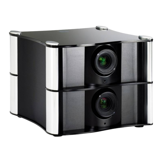
System Overview The standard D-113d projector, shown in Figure 2-2, consists of two discrete optical engines stacked one on top of the other to provide either three-dimensional (3D) or Projector two-dimensional (2D) content. For 3D content, each engine produces images for one eye. Two dichroic comb filters – installed between the lamp and the lens in each engine –... -
Page 25: D-113D Input Panel
System Overview 1. RIGHT (INTAKE) SIDE PANEL The right side panel is perforated to allow cool air to enter the projector. 2. LEFT (EXHAUST) SIDE PANEL The left side panel is perforated to allow warm air to exit the projector. Removing this panel provides access to the lamps. - Page 26 System Overview 1. GPIO Not used. 2. RS232 IN Connect the RS-232 output from the DHD Controller here, using the provided RJ11-to-DB9 adapter and communication cable. 3. PWR LED Lights green to indicate that power is applied and the HDMI input module is initialized. During normal operation, always on.
-
Page 27: Primary Dhd Controller
System Overview The Primary DHD Controller provides a video signal and OSD menu to the left-eye optical engine of the projector. It controls the other D-113d system components in response to Primary DHD user input via the following interfaces: Controller •... - Page 28 System Overview 1. RUNCO ICON Lights blue to indicate that the controller is on or powering up. 2. IR SENSOR Receives IR commands from the remote control. 3. VACUUM FLUORESCENT DISPLAY Can be used instead of the On-Screen Display (OSD). Displays currently-selected menu or –...
-
Page 29: Rear Panel Layout
System Overview Figure 2-5 shows the rear connector panel on the Primary DHD Controller. Rear Panel Layout TRIGGERS Display Control RS-232 Do not connect any video source directly to this box. HDMI Out HDMI 3 HDMI 1 To Display Video RS232 Video 3 Video 3... - Page 30 System Overview 10. HDMI 1 Input (Digital) Connect the HDMI 1 input to the Left HDMI output on the 3Dimension Processor. The HDMI 2, HDMI 3 and HDMI 4 inputs are not used with the D-113d. Connect your HDMI sources to the 3Dimension Processor. 11.
-
Page 31: Secondary Dhd Controller
Video 3 DHD4 Secondary Figure 2-6. Secondary DHD Controller Front and Rear Panels 1. RUNCO ICON Lights blue to indicate that the controller is on or powering up. 2. MAIN POWER SWITCH Disconnects or applies power to the DHD Controller. -
Page 32: 3Dimension Processor
System Overview 7. HD2 Input (5 x Analog BNCs) Connect the HD 2 input to the Right Analog output on the 3Dimension Processor. The HD 1 input is not used with the D-113d. Connect your Component/RGBHV sources to the 3Dimension Processor. 8. - Page 33 System Overview 1. RUNCO ICON Lights blue to indicate that the 3Dimension Processor is on or powering up. 2. MAIN POWER SWITCH Disconnects or applies power to the 3Dimension Processor. 3. POWER INPUT (100 to 240 VAC) Connect the 3Dimension Processor to power here.
-
Page 34: Dhd Controller Remote Control Unit
System Overview Figure 2-8 shows the D-113d remote control, and the paragraphs that follow describe its functionality. DHD Controller Remote Control Unit LIGHT RATIO RATIO EXIT MENU CUST CUST COMP HDMI HDMI SCART HDMI HDMI NATIVE 16 : 9 4 : 3 V-WIDE CINEMA V-CINE... - Page 35 System Overview 1. IR OUTPUT INDICATOR Lights when a button is pressed to indicate that an IR signal is being transmitted. 2. LIGHT Press to illuminate the buttons. 3. ON / OFF Press to turn the DHD Controller and projector on or off. 4.
- Page 36 System Overview 10. HD 1 (4) / HD 2 (5) Press to select a HD (RGBHV or YPbPr component) input or to enter the numeric character “4” or “5.” 11. COMP (Component) (6) Press to select the Component video input as the source or to enter the numeric character “6.”...
-
Page 37: Installation
Installation 3. Installation Installation must be performed by a qualified custom video Note installation specialist. Due to the weight, size and complexity of the D-113d Projection System, two persons are recommended for some of the procedures described here. To install batteries in the remote control: Remote Control 1. -
Page 38: Notes On Remote Control Operation
Installation Notes on Remote Control • Make sure that there is nothing obstructing the infrared beam between the remote Operation control and the IR receiver on the DHD Controller. • If the effective range of the remote control decreases, or it stops working, replace the batteries with new ones. -
Page 39: Installation Considerations
Installation Table 3-1. Installation Overview (continued) For rear-screen installations, select the proper picture orientation Use Image Alignment controls to fine-tune image geometry Install CineWide anamorphic lens (optional) Adjust CineWide anamorphic lens: position, pitch (angle), geometry and focus DHD Controller input calibration: adjust the following for each 64 through 84 DHD Controller input and display mode (resolution/frame rate);... -
Page 40: Ambient Light
Installation Ambient Light In general, minimize or eliminate light sources directed at the screen. Contrast ratio in your images will be noticeably reduced if light directly strikes the screen, such as when a shaft of light from a window or floodlight falls on the image. Images may then appear washed out and less vibrant. -
Page 41: Vertical And Horizontal Position
Minimum Maximum For rear-screen installa- tions only. Contact Athena Uno cannot be used with an Athena Uno 0.70 (Fixed) Runco Technical Support anamorphic lens. for more information. Athena Dos cannot be used with an Athena Dos 1.46 - 1.85 175.20 222.00... -
Page 42: Vertical And Horizontal Lens Shift
Installation Vertical and Horizontal You can use the lens shift controls to center the image on the screen. Lens shift is Lens Shift generally expressed as a percentage of the screen height or width, as shown in Figure 3-3 and Figure 3-4. 100% Height Lens Shift (1.0 x H) -
Page 43: Audio/Video Synchronization Issues
In order to easily Synchronization Issues solve this issue, Runco recommends using the DHD Controller with a high-quality audio receiver that has the ability to effectively synchronize audio and video signals. -
Page 44: Ventilation
Installation Table 3-5. Possible Audio Latency for Various Input Timings (continued) Input Timing Possible Audio Latency (milliseconds) 1080i/25 1080i/30 1080p/24 1080p/50 1080p/60 Ventilation If you are mounting the D-113d in an enclosure, leave at least 10 inches (250 mm) of space on the left and right sides between it and surrounding objects, as shown in Figure 3-5. -
Page 45: Installing The Optional Cinewide With Autoscope Lens Motors
Installation Your D-113d/CineWide with AutoScope may have shipped with the Installing the Optional Note AutoScope lens motors pre-installed. If so — or if you are installing CineWide with a standard D-113d (without an anamorphic lens) — skip this step AutoScope Lens and proceed with Assembling the Projection System (page 30). -
Page 46: Assembling The Projection System
Installation DO NOT OVER-TIGHTEN THE SCREWS. Caution 4. Place the bottom projection unit (the one with pockets and tapped holes in place of the cosmetic caps on the top) upside down on a smooth, flat surface covered with a blanket or other soft material. Loosen and remove the two front feet on the projection unit. -
Page 47: Attaching The Top And Bottom Projection Units To Each Other
Installation 1. With the help of an assistant, carefully lift the top projection unit and place it right Attaching the Top and side up on a flat surface. Bottom Projection Units to Each Other 2. Repeat Step 1 for the bottom projection unit. 3. -
Page 48: Mounting The D-113D
Installation Place the D-113d on a strong supporting structure or cart. Carts can be useful when moving a projector during a presentation or from site to site. If possible, lock the wheels Mounting the D-113d when it’s in position to prevent it from being moved during a presentation. Take special care if using a mobile cart;... - Page 49 Installation 5. Remove and retain the two security screws from the lens mount. Security Screws 6. Align the lens interface plate with the lens mount. Align the lens electrical connector with the mating connector on the lens mount. Fully insert the assembly straight into the lens mount opening without turning.
-
Page 50: Mounting The Dhd Controllers And 3Dimension Processor
2U (3.5 inches) or more of vertical rack Primary DHD Controller space (at least 10.5 inches total). To minimize cable clutter, Runco recommends that you install the 3Dimension Processor between the Primary and 3Dimension Processor Secondary DHD Controllers in the rack. -
Page 51: System Interconnections
Installation Proceed as follows to connect the D-113d system components to each other and to AC power. System Interconnections When connecting your equipment: • Turn off all equipment before making any connections. • Use the correct signal cables for each source. •... -
Page 52: Connecting The Primary And Secondary Dhd Controllers To The Projector
Installation Figure 3-11 shows how to connect the Primary and Secondary DHD Controllers to the projector. Primary DHD Controller PRIMARY TRIGGERS Display Control RS-232 Do not connect any video source directly to this box. HDMI Out HDMI 1 HDMI 3 To Display Video RS232... -
Page 53: Connecting The Primary And Secondary Dhd Controllers To Each Other And To The 3Dimension Processor
Installation Figure 3-12 shows the connections between the 3Dimension Processor and Primary and Connecting the Primary Secondary DHD Controllers. and Secondary DHD Controllers to Each Other and to the 3Dimension Primary DHD Controller Processor Display Control TRIGGERS RS-232 Do not connect any video source directly to this box. HDMI Out HDMI 1 HDMI 3... - Page 54 Installation To make these connections easier, the rear-panel connectors on the 3Dimension Processor and DHD Controllers are identified and color-coded as follows: Identifier Color/Function A, B, C, D, E Green - Analog (HD) video from 3Dimension Processor to Primary DHD Controller Red - Analog (HD) video from 3Dimension Processor to Secondary DHD Controller Green - Analog (SD) video from 3Dimension Processor to Primary...
-
Page 55: To The Primary Dhd Controller (Optional)
Installation The DHD Controller provides a second HDMI output (labeled HDMI Out (Audio Only)) for Connecting an Audio connection to an audio receiver/switching system or secondary display device for Processor or Secondary monitoring purposes. See Figure 3-13. Display Device to the Primary DHD Controller (Optional) The DHD Controller does not transmit HDMI CEC control... -
Page 56: Additional Connections To The Primary Dhd Controller (Optional)
Installation Additional Connections to The DHD Controller provides the following interfaces to external equipment that allow it to the Primary DHD control or be controlled by that equipment: Controller (Optional) • An RS-232 interface to a PC or control/automation system; •... -
Page 57: Connecting 12-Volt Trigger Outputs
Installation Connecting 12-volt Trigger Outputs to External Equipment: If you are installing a D-113d/CineWide with AutoScope, connect the AutoScope lens motor on the top (left-eye) optical engine to a 12-volt trigger output on the Primary DHD Controller; see Figure 3-15. Connect the the AutoScope lens motor on the bottom (right-eye) optical engine to a 12-volt trigger output on the Secondary DHD Controller. - Page 58 Installation Connecting an External IR Receiver to the DHD Controller: If infrared signals from the remote control cannot reach the DHD Controller due to excessive distance or obstructions such as walls or cabinet doors, you can connect an external IR receiver to extend the range of the remote control.
-
Page 59: Ethernet Network Connection To Primary Dhd Controller
Installation Ethernet Network Connection: Use a standard, Category 5 network cable with an RJ-45 plug to connect a network hub, router or gateway to the Ethernet port on the Primary DHD Controller; see Figure 3-17. Display Control Display Control RS-232 RS-232 To Accessory Box To Accessory Box... -
Page 60: Connecting Source Components To The 3Dimension Processor
Installation Connecting Source Connect your video sources to the 3Dimension Processor as shown and described in the Components to the sections that follow. 3Dimension Processor HDMI Source Connections: See Figure 3-18. Use the HDMI inputs whenever possible. This ensures the highest video quality because the signal is carried in the digital domain throughout the entire signal path, from source component output into the projector. -
Page 61: Component Video Source Connections
Installation Component Video Source Connections: Connect your component video sources to the HD1, HD2 and/or Component/SCART inputs as shown in Figure 3-19. Component/SCART Video 1 Video 1 Video 2 Video 2 Video 3 Video 3 RCA-to-BNC adapter COMPONEN T VIDEO OUT DTV-Set-Top Box (DTV-STB) BD/DVD... -
Page 62: Rgbhv Source Connections
Installation RGBHV Source Connections: Connect personal computers and/or other RGB sources to the HD1 and/or HD2 inputs as shown in Figure 3-20. RGB Camcorder Computer Figure 3-20. RGBHV Source Connections D-113d Projection System Installation/Operation Manual... -
Page 63: Scart Rgbs Source Connections
Installation SCART RGBS Source Connections: Connect the green, blue and red outputs from your SCART source to the Component/SCART input on the 3Dimension Processor. Connect the sync output from your SCART source to the Video 1 input on the 3Dimension Processor. See Figure 3-21. INPUTS Component/SCART HDMI 1... -
Page 64: Connecting To Ac Power
Installation Composite Source Connections: See Figure 3-22. INPUTS Component/SCART HDMI 1 HDMI 3 Video 1 Video 2 Video 3 3Dimension HDMI 2 HDMI 2 Processor Composite Camcorder Composite Composite Gaming Console Figure 3-22. Composite Video Source Connections Connecting to AC Power Projector: The projector ships with two (2), AC power cords: one for the DHD Controller and one for the projector. -
Page 65: Power-Up Sequence And Optical Alignment Procedure
Installation At this point you are ready to perform the initial power-up sequence and optical alignment 3.10 procedure, which is summarized in Table 3-6 and described in detail in the sections that Power-Up Sequence follow. and Optical Alignment Procedure This procedure assumes the following: •... - Page 66 Installation Table 3-6. D-113d Optical Alignment Procedure (with Anamorphic Lenses) (continued) Projector (Align Secondary/Right Image with Screen) Select Calibration -> Adjustment Mode Adjust Focus using the focus test and set it to Secondary. pattern. Select Service -> Display Device -> Adjust Zoom and Position using the Configure ->...
-
Page 67: Turning On The Power
Installation Table 3-6. D-113d Optical Alignment Procedure (with Anamorphic Lenses) (continued) DHD (Align Secondary Image with Primary Projector Notes: Image) The Primary lens image is usually left Select Calibration -> Adjustment Mode No adjustment needed. un-warped. This provides the best and set it to Secondary. -
Page 68: Adjusting The Focus, Zoom And Position Of The Primary Lenses
Installation 5. When the display is ready for use, the fluorescent display indicates the active source, input resolution/frame rate and aspect ratio/screen; for example: Current Source HDMI 1 D-113d 16:9/1 1080i/60 1080p/60 Aspect Ratio/Screen Input Resolution/Frame Rate Adjusting the Focus, Lens zoom, focus and position are motorized adjustments that are adjustable using the Zoom and Position of the remote control (Figure 2-8). -
Page 69: Adjusting The Picture Orientation
Installation 11. Adjust Position of Left (Top) Primary Lens: To change the lens position, use the cursor buttons to highlight “Left,” “Right,” “Up” or “Down” in the Lens menu. Then, press and hold the ENTER button to shift the lens in that direction. To return the lens to its home position (no horizontal or vertical shift), use the cursor buttons to highlight “Home”... -
Page 70: Adjusting The Image Geometry
Installation Adjusting the Image Projector and/or screen placement — among other things — can cause geometric Geometry distortion in the projected image. To correct this, the DHD Controller provides precise, nine-point control over the projected image geometry. Use these controls as (and only if) needed to re-position the image corners, mid-points and center to eliminate “keystoning”... -
Page 71: Image Alignment Controls
Installation To correct keystoning or pincushion distortion: 1. On the DHD Controller remote control or front panel, press MENU. 2. Select Calibration from the Main Menu and enter the Calibration Menu passcode. You must enter a passcode to access the Calibration menu. Note 3. -
Page 72: Installing And Adjusting The Cinewide Anamorphic Lens
The D-113d Anamorphic lens mount kit consists of everything shown in Figure 3-25. Some components shipped with your projector may differ slightly from what is shown in these instructions. If any items are missing or damaged, please contact your Runco dealer or Runco Customer Service at (800) 23-RUNCO. - Page 73 Installation Attach Lens Mounting Assembly to Lens Motor Carriage Plate: 1. Remove the two Yaw/X Adjustment Levers and Washers (item #8) from the bottom of the Anamorphic Lens Holder (item #6). 2. Place the Anamorphic Lens Holder on top of the AutoScope Carriage Plate (item #7). Position the bracket so that the long slot at the bottom of the lens holder is perpendicular to the corresponding slots on the plate.
- Page 74 Installation Configure Lens Motor Trigger (CineWide with AutoScope): CineWide with AutoScope maintains constant image height independent of the aspect ratio, while using the full display resolution of the projector. It accomplishes this by moving the anamorphic lens in front of the primary lens when widescreen material is being viewed. When the viewer transitions back to 16:9 or 4:3 source material, the anamorphic lens moves out of the light path.
- Page 75 Note properly adjusted, especially at shorter throw distances. If this is the case, Runco recommends that you slightly over-scan the image into the screen frame area to mask the distortion. Yaw Adjust: Loosen the Yaw/X-Adjustment Levers to allow the lens to pivot freely from side to side.
-
Page 76: Working With The Lamp
Installation Geometry: 1. Unscrew the Anamorphic Lens just enough to allow it to rotate freely. 2. Grasp the lens by the center ring and rotate the lens until the image is properly anamorphic: Wrong Position Correct Position 3. When the image geometry appears correct, tighten the Anamorphic Lens Set Screw (item #3) to secure the lens in place. -
Page 77: Operation
Operation 4. Operation To display the Main Menu, press the MENU button on the remote control or Primary DHD Controller front panel (Figure 2-4). Using the On-Screen Menus To select a menu item, use the buttons on the remote control or Primary DHD Controller front panel to highlight it. - Page 78 Operation Composite 1 Gain -100, -99... 0 ... 99, 100 (Red, Green, Blue) Offset Composite 2 Mode Composite 3 (Simple / Advanced) Component Simple HD 1 Gamma (1.00, 1.01, 1.02 ... 2.20 ... 3.38, 3.39, 3.40) Input Source HD 2 Advanced Display Color - SCART...
- Page 79 Auto Check for New Firmware, Auto Auto Firmware Upgrade Perform Upgrade, Check for New Firmware Network E-Mail Address, Error Notification, Error Notification to Runco, Periodic Service E-Mail Notification Notification, Lamp Life Notification, Customer Information, E-Mail Calibration Data Service Remote Network Control...
-
Page 80: Main Menu
For more information, refer to Picture Adjustment Mode on page 85. Input Position When you set the Adjustment Mode to Primary or Secondary, the Memory Presets Main Menu title becomes “Runco Video (Pri.)” or “Runco Video 3D Processing (Sec.)” respectively. Sleep Timer Information Calibration... - Page 81 Operation Table 4-1. Aspect Ratio Settings Remote Aspect Ratio Control Description 16:9 16:9 Select 16:9 to view 16:9 DVDs and HDTV programs in their native aspect ratio. 16:9 Image on 16:9 Screen (Display) 4:3 images are stretched horizontally to fit a 16:9 screen. 4:3 Image, stretched to fill 16:9 Screen (Display) Standard 4:3 scales the input...
- Page 82 Operation Table 4-1. Aspect Ratio Settings (continued) Remote Aspect Ratio Control Description Cinema CINEMA Select Cinema to view 2.35 source material in its native aspect ratio. With a 16:9 screen and a standard D-113d (without an anamorphic lens), the upper and 2.35:1 Image on lower portions of the screen are 16:9 Screen...
-
Page 83: Screen
Color obtain optimal picture quality from Runco video display devices. Accordingly, Runco Tint recommends that setup and calibration be performed by an ISF certified installation Sharpness technician. - Page 84 Operation Brightness: On your external test pattern source, select a PLUGE pattern. (PLUGE is an acronym for “Picture Line-Up Generation Equipment.”) Figure 4-2 shows a typical PLUGE pattern. Below Black Above Black Figure 4-2. Typical PLUGE Pattern for Adjusting Brightness PLUGE patterns vary but generally consist of some combination of black, white and gray areas against a black background.
- Page 85 Operation Contrast: On your external test pattern source, select a stepped, gray-bar pattern like the one shown in Figure 4-3. Figure 4-3. Typical Gray Bar Pattern for Adjusting Contrast Select Contrast and press ENTER. Adjust the contrast to a point just below which the white rectangle starts to increase in size.
- Page 86 Operation 6. Select Diagnostics and press ENTER. 7. Select Blue from the Diagnostics menu, then press ENTER to display only the blue color channel. 8. Press EXIT (or MENU) repeatedly to return to the Main Menu. 9. Select Picture from the Main Menu and press ENTER. 10.Select Color from the Picture menu and press ENTER.
-
Page 87: Input Position
Operation Sharpness: “Sharpness” is the amount of high-frequency detail in the image. To adjust sharpness, select Sharpness from the Picture menu and press ENTER. On your external test pattern source, select a pattern like the one shown in Figure 4-5. Adjust as needed, looking for white edges around the transitions from black to gray and differently-sized lines in the “sweep”... - Page 88 Operation Height: Select Height from the Input Position menu to change the projected image height. Press to increase the height; press to decrease it. Overscan/Overscan Mode: Overscan pushes the outside edge of the active picture area of the video signal out beyond the edge of the display area. Some television programs are produced based on the assumption that older television sets may not display the outer edges of the broadcast picture area.
-
Page 89: Memory Presets
Operation Phase (RGB, Component or SCART sources): This control adjusts the phase of the pixel sampling clock relative to the incoming signal. Adjust the phase when an RGB, Component or SCART image still shows shimmer or “noise” after Tracking has been optimized. -
Page 90: 3D Processing
Operation You should save changes to any of the following settings to a preset; otherwise they will be lost when a new input source or resolution is selected: • Brightness • Contrast • Color saturation • Tint • Sharpness • Gamma •... -
Page 91: Sleep Timer
Operation • Choose Frame Packing to have the 3Dimension Processor decode frame packed data into left and right eye data. In this mode, the DHD Controllers do not perform any 3D processing. Reverse Eyes: By default, the Primary and Secondary DHD Controllers are dedicated to “left eye”... -
Page 92: Information
Information your DHD Controller and display device. Signal System Should you ever need to contact Runco Technical Support, this information will help them Network answer your questions or resolve product performance issues. Field Service Manufacturing... -
Page 93: Calibration
Operation Use the Calibration menu to perform advanced picture quality adjustments. This menu Calibration should be used by ISF-certified technicians only. Calibration You must enter a passcode to access the Calibration menu. ISF Settings Note Display Color Input Image Input Color To recall the ISF Night or ISF Day settings, select “ISF Night”... - Page 94 Operation • Color Temp: Select Color Temp from the Display Color - Common Settings menu to adjust the color temperature. Color temperature establishes the “color of gray” by adjusting the 75% white point to various color points. What are “color points?” A “color point” is an x/y coordinate pair that defines a color’s location on the standard CIE chromaticity graph, shown in Figure 4-7.
- Page 95 Operation Table 4-2 lists the x- and y-coordinates for each color temperature preset in “Simple” mode. Table 4-2. Color Temperature Presets and Associated Color Points Associated x/y Values Color Temperature Preset 3200K 0.423 0.404 5500K 0.332 0.348 6500K 0.313 0.329 7500K 0.299 0.315...
- Page 96 Operation Table 4-3 lists the Color Gamut settings and associated x- and y-coordinates for each primary and secondary color component. Table 4-3. x/y Color Gamut Values Color Gamut Settings and Associated x/y Values Primary REC709 SMPTE “C” Color 0.640 0.330 0.635 0.340 0.640...
- Page 97 Operation The Auto Color Enable and Test Pattern Enable checkboxes let you choose what to display on-screen while making these adjustments. These controls work together as follows: Auto Color Enable Test Pattern Enable Description Setting Setting When both boxes are unchecked, the input signal (normal picture) appears on the display.
- Page 98 Settings menu to enable (On) or disable (Off) ConstantContrast in the optical engine. ConstantContrast uses a dynamic iris that modulates light to the DMD based on the actual content of the video material. Runco recommends that you disable ConstantContrast before adjusting Brightness, Contrast or other image settings, or if you change the RVR setting (see below) to something other than the default value.
- Page 99 Operation Input Color: The Input Color controls are similar to those in the Display Color menu (see above), but adjust the color balance of the incoming signal. These settings are also saved independently for each input and display mode. • Gain/Offset (HD1, HD2 and Component/SCART inputs only): These controls operate similarly to those in the Display Color - Common Settings menu (described on page 77), but affect the Y, Pb and Pr signal components rather than the red, green and blue channels.
- Page 100 Operation • Memory Preset - Paste Settings: To apply the settings on the clipboard to a different input source, signal format and/or memory preset, do any or all of the following: • Switch to another input (for example, from HD1 to HD2). •...
- Page 101 Adjustment Mode from the Calibration menu and set it to Primary or Secondary. The Main Menu title changes to “Runco Video (Pri.)” or “Runco Video (Sec.)” when you do this. Lens controls are not available when the Adjustment Mode is set to Note Both.
-
Page 102: Service
Operation Service Use the Service menu to access advanced projector configuration settings. This menu should be used by ISF-certified technicians only. Service Test Video You must enter a passcode to access the Service menu. Note Input Names Display Device Network Test Video: Select Test Video from the Service Menu to access the internal test patterns Color Space on the DHD Controller. - Page 103 Operation Table 4-4. Test Patterns and Their Suggested Usage (continued) Pattern Suggested Usage Use this pattern when aligning the output from the projector’s primary or secondary optical Primary Alignment engines (refer to Power-Up Secondary Sequence and Optical Alignment Alignment Procedure on Dual Alignment page 49).
- Page 104 Operation Display Device - Configure: The options in the Display Device - Configure menu allow you to change the picture orientation, perform lens adjustments or access other, display-device specific functions. • Installation – Orientation: Select Installation from the Display Device - Configure menu, then select Orientation to change the picture orientation to suit the method of installation (Floor Front or Floor Rear).
- Page 105 Operation Network: The options in the Network menu allow you to configure the network communication features. • IP Configuration: Select IP Configuration from the Network menu to either set the IP address, subnet mask and default gateway of the DHD Controller manually or obtain these settings automatically, from a DHCP (Dynamic Host Configuration Protocol) server.
- Page 106 [E-Mail Address; see below] From: do-not-reply@runco.com Subject: [Type of notification] from Runco DHD4 Body: This is an automated message sent from the Runco DHD4: Notification: [One of the following: “DHD Error” / “Display Error” “Periodic Service Notification” “Lamp Life Notification” / “Calibration Data”] Detailed Description: [ If a DHD Error, one of the following: “Fan Failure 1”...
- Page 107 “DHD Error” or “Display Error” occurs, select Error Notification from the E-Mail Notification menu and set it to On. • Error Notification to Runco: To have the DHD Controller send an e-mail message to Runco Customer Support when a “DHD Error” or “Display Error” occurs, select Error Notification to Runco from the E-Mail Notification menu and set it to On.
- Page 108 Operation • E-Mail Calibration Data: To have the DHD Controller collect all calibration data, attach it to a message and send it to the destination e-mail address, select E-Mail Calibration Data from the E-Mail Notification menu. To confirm this action, select Yes and press ENTER.
- Page 109 Operation Miscellaneous: Select Miscellaneous from the Service menu to set the following options: • Language: Select Language from the Miscellaneous menu and press the up- or down-arrows to select the OSD Language (English, Français, Deutsch, Italiano, Español, Svenska, (Simplified Chinese), (Traditional Chinese), Português, (Russian),...
- Page 110 Operation When you change a remote code on the DHD Controller, you must re-program the DHD Controller remote control to send that same code. To do this: 1. Press and hold the LIGHT button on the remote control for approximately three LIGHT seconds, or until the LED on the remote lights solid red.
- Page 111 Operation • HPD Toggle Rejection: Select HPD Toggle Rejection from the HDMI menu to specify whether or not the DHD Controller ignores extraneous Hot Plug Detect (HPD) signal state changes from a downstream HDMI device (third-party display or audio/video receiver). The default setting, Auto, enables HPD toggle rejection on the D-113d.
- Page 112 Operation Standby Mode: Select Standby Mode from the Service menu to control the DHD Controller’s power management feature. • Choose Low Power (the default setting) to have the DHD Controller shut down completely when it is turned off. This conserves power but increases the amount of time required by the DHD Controller to start up when it is turned on.
-
Page 113: Maintenance And Troubleshooting
Device -> Configure -> Display Info., in sequence). For lamp replacement, please contact your nearest Runco authorized service center or Runco dealer. Do not attempt to replace the lamp yourself! 1. Remove the two screws securing the Left (Exhaust) Side Panel (see Figure 2-2) to the projector. - Page 114 Handle lamps with extreme caution. Dispose of lamps according to WARNING safety regulations for your area. Discard the lamp using safe disposal/recycling practices or contact your Runco dealer for a possible re-lamping program. 5. Install the new lamp: a Take care to align the new lamp properly in the correct orientation inside the lamp compartment.
-
Page 115: Troubleshooting Tips
Table 5-1 provides some general guidelines for troubleshooting problems you may encounter with the D-113d. If the suggested solutions fail to resolve the problem or if you Troubleshooting Tips encounter an issue not described here, please contact Runco Technical Support. Table 5-1. Troubleshooting Chart Symptom... - Page 116 Maintenance and Troubleshooting Table 5-1. Troubleshooting Chart (continued) Symptom Possible Cause(s) Solution The display is jittery or • Poor-quality or improperly • Ensure that the source is unstable. connected source. properly connected and of adequate quality for detection. • The horizontal or vertical •...
- Page 117 Maintenance and Troubleshooting Table 5-1. Troubleshooting Chart (continued) Symptom Possible Cause(s) Solution The projector does not turn • The serial connection from • Ensure that the on or respond to user com- the Primary DHD Display Control (RS-232) mands. The vacuum fluores- Controller to the display is output from the Primary cent display on the Primary...
- Page 118 Maintenance and Troubleshooting Notes: D-113d Projection System Installation/Operation Manual...
-
Page 119: External Control
Runco products (manufactured prior to September 2011) that include the DHD Controller. Runco recommends using this new protocol, as it is more concise and provides greater control than the old one. However, to maintain backward compatibility with existing automation/control system modules, the legacy Runco serial protocol is also supported. -
Page 120: Response Format
External Control • y is the operand, which can have one of the following values: ? = “Get” operand + = “Increment” operand = = “Set” operand - = “Decrement” operand • z is the value to set for this parameter. It can have one of two formats: •... -
Page 121: Command And Response Examples
External Control Here are some examples of serial commands and their responses: Command and Response Examples Command Command Data Response Power query when (PWR?) [CR] (0;PWR=1) [CR] unit is powered on Set power to 0 (off) (PWR=0) [CR] (0;PWR=0) [CR] Increment bright- (BRT+) [CR] (0;BRT=25) [CR]... - Page 122 External Control Table 6-1. Serial Commands (continued) Command Read/ Inc/ Setting String? Notes Code Write Value Value Aspect Ratio Copy Action will be performed on any setting value Aspect Ratio Paste PCE Red x -100 PCE Red y -100 Aspect Ratio 0 = 4:3 1 = 16:9 2 = Letterbox...
- Page 123 External Control Table 6-1. Serial Commands (continued) Command Read/ Inc/ Setting String? Notes Code Write Value Value Color Calibration -> Input Image menu Color Space 0 = REC601 1 = REC709 2 = RGB 3 = RGB Video 4 = Auto Image Alignment Center x -100 Image Alignment Center y...
- Page 124 External Control Table 6-1. Serial Commands (continued) Command Read/ Inc/ Setting String? Notes Code Write Value Value Error Notification 0 = Off; 1 = On Error Code 0 = None 1 = Display Lamp Overtemp 2 = Primary Display Ballast Over- temp 3 = Primary Display Fan Init Failure 4 = Primary Display Fan 1 Failure...
- Page 125 External Control Table 6-1. Serial Commands (continued) Command Read/ Inc/ Setting String? Notes Code Write Value Value Error Code 37 = Secondary Display Fan 2 Fail- 38 = Secondary Display Fan 3 Fail- 39 = Secondary Display Fan 4 Fail- 40 = Secondary Display Fan 5 Fail- 41 = Secondary Display Fan 6 Fail- 42 = Secondary Display Fan 7 Fail-...
- Page 126 External Control Table 6-1. Serial Commands (continued) Command Read/ Inc/ Setting String? Notes Code Write Value Value Gamma Simple 0 = 2.0 1 = 1.8 2 = 2.2 3 = 2.35 4 = 2.5 HDMI Audio Format 0 = Combined 1 = HDMI Out 1 2 = HDMI Out 2 HDMI EDID Extension 1...
- Page 127 External Control Table 6-1. Serial Commands (continued) Command Read/ Inc/ Setting String? Notes Code Write Value Value Information Copied Memory Pre- Information Copied Screen Information Copied Signal Format Information Display Name Information Firmware Version Input Green Gain Input Green Offset Information Horizontal Frequency Information Input Resolution information Micro Version...
- Page 128 External Control Table 6-1. Serial Commands (continued) Command Read/ Inc/ Setting String? Notes Code Write Value Value Information Sync Type 0 = None 1 = Separate 2 = Composite 3 = Sync-on-green Information Vertical Frequency Remote Key 1 = On 2 = Off Remote Key Repeat 3 = Menu...
- Page 129 External Control Table 6-1. Serial Commands (continued) Command Read/ Inc/ Setting String? Notes Code Write Value Value Language 0 = English 1 = French 2 = German 3 = Italian 4 = Spanish 5 = Portuguese 6 = Simplified Chinese 7 = Traditional Chinese 8 = Swedish 9 = Russian...
- Page 130 External Control Table 6-1. Serial Commands (continued) Command Read/ Inc/ Setting String? Notes Code Write Value Value OSD Position Horizontal Output Shift Height Output Shift Left Right -300 OSD Message Enable 0 = Off; 1 = On OSD Timer Values from 1-4 are not allowed; if increment or decrement is used, these values will be skipped.
- Page 131 Sidebar Color Blue Sidebar Color Green Screen 0 = Screen 1 1 = Screen 2 Sidebar Color Red Send Errors to Runco 0 = Off; 1 = On Sharpness Offset Picture menu Sharpness Calibration -> Input Image menu Screen Masking Bottom Screen Masking Test Pattern 0 = Off;...
- Page 132 External Control Table 6-1. Serial Commands (continued) Command Read/ Inc/ Setting String? Notes Code Write Value Value Trigger 1 16:9 Trigger 1 4:3 Trigger 1 Letterbox Trigger 1 VirtualWide Trigger 1 Cinema Trigger 1 Virtual Cinema Trigger 1 Native Trigger 2 16:9 Trigger 2 4:3 Trigger 2 Letterbox Trigger 2 VirtualWide...
- Page 133 External Control Table 6-1. Serial Commands (continued) Command Read/ Inc/ Setting String? Notes Code Write Value Value Tint Calibration -> Input Image menu Test Pattern Enable 0 = Off; 1 = On Primary Test Pattern 0 = Off; 1 = On Secondary Test Pattern 0 = Off;...
-
Page 134: Using Discrete Ir Codes
External Control The DHD Controller accepts commands in the form of IR signals that conform to the Phillips RC5 protocol. Each DHD Controller remote control button has an RC5 control Using Discrete IR code associated with it. Codes You can use these codes to program a third-party, “universal” remote control unit to work with the DHD Controller. - Page 135 External Control For example, here is the RC5 control code for the ON button on the DHD Controller remote control unit (assuming the default address is used): With Toggle Bit = 0 Binary With Toggle Bit = 1 Binary Start Toggle Function Address...
-
Page 136: Ir Command List
External Control IR Command List Table 6-2 lists the RC5 control codes for the DHD Controller. Table 6-2. RC5 Control Codes for the DHD Controller RC5 Data RC5 Data from with Toggle Function Remote Description Bit = 1 Control (Note) (Note) 16:9 0x3449... - Page 137 External Control Table 6-2. RC5 Control Codes for the DHD Controller (continued) RC5 Data RC5 Data from with Toggle Function Remote Description Bit = 1 Control (Note) (Note) 0x3441 0x3C41 Power on RIGHT 0x3448 0x3C48 Right-Arrow ( SCART 0x3457 0x3C57 SCART video input SCREEN1 0x3466...
-
Page 138: Using Hdmi Cec Messages
External Control The DHD Controller accepts and can respond to CEC command messages from a disc player, satellite receiver or DVR/set-top box via an HDMI connection. Using CEC, the DHD Using HDMI CEC Controller can perform the following actions: Messages •... - Page 139 External Control Table 6-3. CEC Commands Supported by the DHD Controller (continued) Supported? (√ = Yes, – = No) Opcode Value Initiator Follower √ Give Physical Address 0x83 – √ Set Stream Path 0x86 – √ Get CEC Version 0x9F –...
- Page 140 External Control Notes: D-113d Projection System Installation/Operation Manual...
-
Page 141: Specifications
Picture Size (16:9 Screen, Recommended Width: 96 - 190 in. Maximum Width: 254 in. Processing: Runco 3Dimension Processor with ViVix IV™ technology and BRiC (Backup, Recovery and Clone) tool Control Options: • Serial commands via RS-232 • Discrete infrared (IR) remote •... - Page 142 Specifications Table 7-1. D-113d Projector Specifications (continued) Light Output (2D): CSMS Specifications* – Private Cinema Calibration: 11,750 ANSI Lumens; 420 Foot-Lamberts (fL) Uncalibrated: 20,000 ANSI Lumens *Measured on a 1.0 gain, 84" wide 16:9 screen Light Output (3D): CSMS Specifications* – Private Cinema Calibration: 1,175 ANSI Lumens;...
-
Page 143: Dhd Controller Specifications
Parameters: Trigger Outputs: (3) +12 VDC, each rated at 250 mA and thermal fuse-protected Accessory Applications: Runco Firmware Upgrader, Runco BRiC (backup, restore, clone), CalMAN by SpectraCal for automatic calibration Power Requirements: 100-240V~, 47-63Hz, 0.45 Amps Operating Environment: 41°F to 104°F (5°C to 40°C), 0% to 90% humidity (non-condensing);... -
Page 144: 3Dimension Processor Specifications
FCC class B, CE, RoHS, China RoHS, WEEE, C-Tick, CCC, local conformances as required Limited Warranty: Two (2) years parts and labor from the date of shipment from Runco. Specifications are subject to change without notice. Table 7-3 lists the 3Dimension Processor specifications. 3Dimension Processor Table 7-3. -
Page 145: D-113D Dimensions
Specifications Figure 7-1 shows the D-113d dimensions. D-113d Dimensions 33.7in 856.6mm 24.0in 610mm Figure 7-1. D-113d Dimensions D-113d Projection System Installation/Operation Manual... -
Page 146: D-113D Dimensions With Cinewide With Autoscope Assembly
Specifications Figure 7-2 shows the D-113d dimensions with the optional CineWide with AutoScope assembly. D-113d Dimensions with CineWide with Foot height AutoScope Assembly Adjustable from .78" to 2.25" 6.8in 2.6in 173.7mm 67.2mm Autoscope height 40.6in 1031.3mm Figure 7-2. D-113d/CineWide with AutoScope Dimensions D-113d Projection System Installation/Operation Manual... -
Page 147: Supported Timings
Specifications Table 7-4 lists the signal types supported by each input on the DHD Controller. Supported Timings Table 7-4. Supported Signal Timings by Input Supported? (√ = Yes, – = No) Horizontal Refresh Pixel Frequency Format Resolution Frequency Rate (Hz) (MHz) (kHz) Supported 3D Modes... - Page 148 Specifications Table 7-4. Supported Signal Timings by Input (continued) Supported? (√ = Yes, – = No) Horizontal Refresh Pixel Frequency Format Resolution Frequency Rate (Hz) (MHz) (kHz) Supported 3D Modes (continued) √ 23.98 26.978 74.175 – – – – √ 24.00 27.000 74.250...
- Page 149 Specifications Table 7-4. Supported Signal Timings by Input (continued) Supported? (√ = Yes, – = No) Horizontal Refresh Pixel Frequency Format Resolution Frequency Rate (Hz) (MHz) (kHz) Supported 2D Modes (continued) √ √ √ 1152x864 1152x864 75.00 67.500 108.000 – –...
- Page 150 Specifications Table 7-4. Supported Signal Timings by Input (continued) Supported? (√ = Yes, – = No) Horizontal Refresh Pixel Frequency Format Resolution Frequency Rate (Hz) (MHz) (kHz) Supported 2D Modes (continued) SCART √ – 50.00 – – – – – –...
- Page 152 020-1165-00 Rev. A October 2011 Runco International • (800) 23RUNCO • Fax (503) 748-8161 • www.runco.com...
Need help?
Do you have a question about the 3Dimension D-113d and is the answer not in the manual?
Questions and answers