Table of Contents
Troubleshooting

Related Manuals for Runco 3Dimension D-73d Ultra


Summary of Contents for Runco 3Dimension D-73d Ultra
- Page 1 N S T A L L A T I O N P E R A T I O N A N U A L 3Dimension™ Series D-73d LED Home Theater Projection System D-73d D-73d/CineWide™ D-73d/CineWide with AutoScope™ D-73d Ultra D-73d Ultra/CineWide™ D-73d Ultra/CineWide with AutoScope™...
-
Page 3: Runcocare™ Standard Two Year Limited Warranty
(if any). You may be required to provide proof of purchase in order to receive warranty services. 1. Runco may update this list of products excluded from this warranty from time to time at Runco’s sole discretion, but updates will not apply on a retroactive basis. - Page 4 Once an RMA has been created, RMA status is available at serviceorders@runco.com. • If an RMA is issued, the dealer or customer will need to return the defective product to the Runco repair depot location specified by the Runco technical support representative. The dealer or customer will need to properly package the defective product in a suitable shipping container consisting of the product only, and not include any accessories (e.g., cables,...
- Page 5 Other Terms and Conditions 1. If the defective product is not properly packaged and is damaged in transit during its return to Runco, you may be invoiced for either the repair costs, if repairable, or the MSRP of a replacement product and shipping costs incurred by Runco.
- Page 6 Runco. The trademarks reproduced in this Runco Owner’s Manual and used on the Runco Products are either owned by Runco or are licensed by Runco. You may not reproduce or use the trademarks without the prior written consent of Runco.
-
Page 7: Important Safety Instructions
Important Safety Instructions Thank you for your purchase of this quality Runco video product! It has been designed to provide you with the quality of video that is expected in a home theater. For the best performance, please read this manual carefully as it is your guide through the menus and operation. - Page 8 The glasses that accompany this product are not safe to use as sunglasses, protective eyewear or any use outdoors or other than only in conjunction with the proper operation of the Runco product with which they are sold. It is common to dim the lights in a home theater. Using 3D glasses and the immersive imagery of stereoscopic imagery can increase the risk of tripping or falling the dark.
-
Page 9: Compliance Information
Council Directive 2006/95/EC and amended by M1 and C1 on Low Voltage Equipment Safety; EN 60950 “Safety of information technology equipment, including electrical business equipment” The Technical Construction file required by this Directive is maintained at the corporate headquarters of Runco International, LLC, located at 1195 NW Compton Drive, Beaverton, OR 97006-1992. - Page 10 FCC PART 15: NOTE: This equipment has been tested and found to comply with the limits for a Class B digital device, pursuant to Part 15 of the FCC Rules. These limits are designed to provide reasonable protection against harmful interference in a residential installation.
-
Page 11: Table Of Contents
Table of Contents RuncoCare™ Standard Two Year Limited Warranty ........... iii Important Safety Instructions ..................vii Compliance Information ....................ix 1. Introduction .......................1 About This Manual .......................1 Target Audience .....................1 If You Have Comments About This Manual.............1 Textual and Graphic Conventions ................1 Using This Manual ......................2 Description, Features and Benefits ................3 Key Features and Benefits ..................4... - Page 12 Table of Contents Installation Considerations ..................23 Installation Type ....................23 Choosing A Screen....................24 Ambient Light .......................24 Throw Distance.....................24 Vertical and Horizontal Position................26 Vertical and Horizontal Lens Shift................26 Folded Optics .......................28 Audio/Video Synchronization Issues..............29 Ventilation ......................30 Other Considerations ....................30 Installing the Optional Anamorphic Lens Mount ............31 Installing the CineWide/AutoScope Lens Motor (D-73d/CineWide with AutoScope) ...............31 Installing the Fixed CineWide Base Plate (D-73d/CineWide) ........34...
- Page 13 Table of Contents 4. Operation .........................65 Using the On-Screen Menus ..................65 Main Menu......................67 Input Source ......................67 Aspect Ratio ......................67 Screen........................70 Picture ........................70 Input Position......................74 Memory Presets ....................76 3D Processing ......................77 Sleep Timer ......................78 Information ......................78 Calibration ......................79 Service .........................86 5. Maintenance and Troubleshooting ................97 Maintenance ......................97 Troubleshooting....................98 6.
- Page 14 Table of Contents Notes: D-73d Series Installation/Operation Manual...
- Page 15 List of Figures 2-1. D-73d Series LED 3-D Home Theater Projection System Block Diagram......7 2-2. Standard D-73d Projector Functional Components ............8 2-3. D-73d Rear Panel.......................10 2-4. Primary DHD Controller Front Panel................11 2-5. Primary DHD Controller Rear Panel ................13 2-6. Secondary DHD Controller Front and Rear Panels............15 2-7.
- Page 16 List of Figures 3-27. Shasta Anamorphic Lens Mounting Assembly - Exploded View........57 3-28. Keystone and Pincushion Distortion .................61 3-29. Image Alignment Controls ..................62 4-1. D-73d OSD Menu Structure ..................65 4-2. Typical PLUGE Pattern for Adjusting Brightness ............71 4-3. Typical Gray Bar Pattern for Adjusting Contrast ............71 4-4.
-
Page 17: Introduction
Target Audience most out of the D-73d. Runco has made every effort to ensure that this manual is accurate as of the date it was printed. However, because of ongoing product improvements and customer feedback, it may require updating from time to time. You can always find the latest version of this and other Runco product manuals on-line, at www.Runco.com. -
Page 18: Using This Manual
Introduction Graphic Conventions: These symbols appear in numerous places throughout the manual, to emphasize points that you must keep in mind to avoid problems with your equipment or injury: TIPS highlight time-saving short cuts and helpful guidelines for using certain features. NOTES emphasize text with unusual importance or special Note significance. -
Page 19: Description, Features And Benefits
3D visualization technology that is based on the science of how the human eye Description, Features and brain process actual depth and dimension in real life. Runco has created a flawless and Benefits stereoscopic video reproduction that is unlike anything else in the home or private cinema market. -
Page 20: Key Features And Benefits
Introduction With Runco CineWide, the projection system is able to use the full pixel array, thereby producing a 2.35:1 image with enhanced resolution and increased brightness. No resolution or image area is lost to those black bars that contain no picture information. -
Page 21: Parts List
Your D-73d is shipped with the following items. If any items are missing or damaged, Parts List please contact your Runco dealer or Runco Customer Service at (800) 23-RUNCO. • D-73d Series LED 3-D Home Theater Projection System: • Projector •... - Page 22 Introduction Notes: D-73d Series Installation/Operation Manual...
-
Page 23: System Overview
2. System Overview The D-73d Series LED 3-D Home Theater Projection System consists of the following components: • The projector, consisting of two discrete LED optical engines stacked one on top of the other to provide either two-dimensional (2D) or three-dimensional (3D) content. •... -
Page 24: Projector
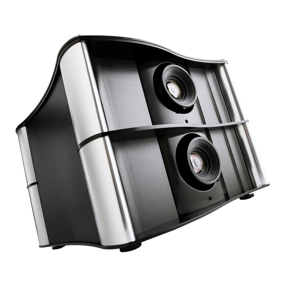
System Overview The standard D-73d projector, shown in Figure 2-2, consists of two discrete LED optical engines stacked one on top of the other to provide either three-dimensional (3D) or Projector two-dimensional (2D) content. For 3D content, each engine produces the image for one eye. Linear polarizers on each engine isolate the output images from one another. - Page 25 The screw to the right of the lens activates the lens lock, which freezes the zoom and lens shift settings to keep the projector images aligned over time. When shipped from Runco, the lenses are unlocked. To lock them, use the same 5.0-mm Hex wrench (provided) that you use for lens shift adjustments. (Turn clockwise two or three turns.)
-
Page 26: Projector Rear Panel
System Overview Projector Rear Panel Figure 2-3 shows the D-73d rear panel. PRIMARY PRIMARY SECONDARY SECONDARY Figure 2-3. D-73d Rear Panel 1. POWER INPUT (Left-Eye Engine – 100 to 240 VAC) Connect the left-eye optical engine to power here. 2. DHD INPUT (Left-Eye Engine) An HDCP-compliant digital video input for connecting the HDMI Out (To Display) from the Primary DHD Controller. -
Page 27: Primary Dhd Controller
System Overview 5. ERROR LED (Left-Eye Engine) Indicates left-eye engine error conditions as follows: • Flashing red = Over temperature, user intervention (clear vents, turn on AC) may fix problem • Solid red = Error that requires servicing (fan failure, Power-on Self-Test (POST) failure). - Page 28 System Overview 1. RUNCO ICON Lights blue to indicate that the controller is on or powering up. 2. IR SENSOR Receives IR commands from the remote control. 3. VACUUM FLUORESCENT DISPLAY Can be used instead of the On-Screen Display (OSD). Displays currently-selected menu or –...
-
Page 29: Rear Panel Layout
System Overview Figure 2-5 shows the rear connector panel on the Primary DHD Controller. Rear Panel Layout TRIGGERS Display Control RS-232 Do not connect any video source directly to this box. HDMI Out HDMI 3 HDMI 1 To Display Video RS232 Video 3 Video 3... - Page 30 System Overview 10. HDMI 1 Input (Digital) Connect the HDMI 1 input to the Left HDMI output on the 3Dimension Processor. The HDMI 2, HDMI 3 and HDMI 4 inputs are not used with the D-73d. Connect your HDMI sources to the 3Dimension Processor. 11.
-
Page 31: Secondary Dhd Controller
Video 3 DHD4 Secondary Figure 2-6. Secondary DHD Controller Front and Rear Panels 1. RUNCO ICON Lights blue to indicate that the controller is on or powering up. 2. MAIN POWER SWITCH Disconnects or applies power to the DHD Controller. -
Page 32: 3Dimension Processor
System Overview 7. HD2 Input (5 x Analog BNCs) Connect the HD 2 input to the Right Analog output on the 3Dimension Processor. The HD 1 input is not used with the D-73d. Connect your Component/RGBHV sources to the 3Dimension Processor. 8. - Page 33 System Overview 1. RUNCO ICON Lights blue to indicate that the 3Dimension Processor is on or powering up. 2. MAIN POWER SWITCH Disconnects or applies power to the 3Dimension Processor. 3. POWER INPUT (100 to 240 VAC) Connect the 3Dimension Processor to power here.
-
Page 34: Dhd Controller Remote Control Unit
System Overview Figure 2-8 shows the D-73d remote control, and the paragraphs that follow describe its functionality. DHD Controller Remote Control Unit LIGHT RATIO RATIO EXIT MENU CUST CUST COMP HDMI HDMI SCART HDMI HDMI NATIVE 16 : 9 4 : 3 V-WIDE CINEMA V-CINE... - Page 35 System Overview 1. IR OUTPUT INDICATOR Lights when a button is pressed to indicate that an IR signal is being transmitted. 2. LIGHT Press to illuminate the buttons. 3. ON / OFF Press to turn the DHD Controller and projector on or off. 4.
- Page 36 System Overview 10. HD 1 (4) / HD 2 (5) Press to select a HD (RGBHV or YPbPr component) input or to enter the numeric character “4” or “5.” 11. COMP (Component) (6) Press to select the Component video input as the source or to enter the numeric character “6.”...
-
Page 37: Installation
3. Installation Installation must be performed by a qualified custom video Note installation specialist. To install batteries in the remote control: Remote Control 1. Press down the tab on the cover and pull the cover in the direction of the arrow. -
Page 38: Quick Setup
Installation Table 3-1 gives a quick overview of the D-73d installation process. The sections following this one provide detailed instructions. Quick Setup Table 3-1. Installation Overview For Details, Refer to Step Procedure page... Choose a location for the projector Choose and install a 3D-compatible screen Install CineWide lens mounting assembly (stationary base plate or AutoScope lens motor –... -
Page 39: Installation Considerations
Installation Proper installation of your projector will ensure the quality of your display. Whether you are installing a projector temporarily or permanently, you should take the following into Installation account to ensure your projector performs optimally. Considerations Choose the installation type that best suits your needs: front or rear screen, floor mount or Installation Type inverted mount. -
Page 40: Choosing A Screen
“ghosting.” Conventional white or gray screens that work just fine for 2D won’t work at all for 3D. Runco has rated home theater screens on their ability to produce 2D and 3D content on a scale it calls PISCES™ (Polarized Image Sequence Conservation and Enhancement Standard). - Page 41 Installation Table 3-3 lists the available lens options for the D-73d and their associated throw ratios. Table 3-3. D-73d Lens Options and Throw Ratios (Note) Throw Range in Throw Range in Throw Ratio inches, with inches, with Throw Ratio with Primary Projector 72.6x40.8-inch (1.78:1) 96x40.8-inch (2.35:1)
-
Page 42: Vertical And Horizontal Position
Installation Vertical and Horizontal Proper placement of the projector relative to the screen will yield a rectangular, Position perfectly-centered image that completely fills the screen. Ideally, the projector should be positioned perpendicular to the screen and in such a way that the lens center is aligned with either the top or bottom edge of the screen area, and centered horizontally. -
Page 43: Horizontal Lens Shift (Example Only)
Installation 100% Width Lens Shift (1.0 x W) 50% Width Lens Shift (0.5 x W) Screen Center Screen Width (W) Note: This is a general example of lens shift. Lenses vary in their shift capabilities. No particular lens or projector is used in this example. Figure 3-4. -
Page 44: Folded Optics
Installation Table 3-4 lists the usable lens shift ranges for each available D-73d lens, as percentages and absolute measurements with a 96 x 54 inch (1.78:1) screen. Table 3-4. Vertical and Horizontal Lens Shift Ranges Lens Configuration Standard or D-73d Ultra Standard Short-Throw (Long-Throw... -
Page 45: Audio/Video Synchronization Issues
In order to easily Synchronization Issues solve this issue, Runco recommends using the DHD Controller with a high-quality audio receiver that has the ability to effectively synchronize audio and video signals. -
Page 46: Ventilation
Installation Ventilation If you are mounting the D-73d in an enclosure, leave at least 3 inches (76.2 mm) of space on the left and right sides between it and surrounding objects, as shown in Figure 3-6. This allows heat to disperse, maintaining the proper operating temperature. Minimum 3.0 in. -
Page 47: Installing The Optional Anamorphic Lens Mount
Installation If you are installing a standard D-73d (without an anamorphic lens), skip this step and proceed with Mounting the D-73d (page 36). Installing the Optional Anamorphic Lens If you are installing a D-73d/CineWide, proceed with Installing the Fixed CineWide Mount Base Plate (D-73d/CineWide) (page 34). -
Page 48: Autoscope Lens Motor Installation
Installation Installing the Lens Motor: 1. Position the AutoScope lens motor as shown in Figure 3-7. 2. Line up the mounting holes on the lens motor housing with those on the underside of the projector. 3. Secure the motor to the projector with the eight (8) supplied M6 x 12mm Pan-Head Phillips screws. -
Page 49: Connecting The Autoscope Lens Motor To The Projector
Installation Connecting the AutoScope Lens Motor to the Projector: Connect the AutoScope lens transport motor to the 12-volt trigger output on the projector (labeled CINEWIDE/AUTOSCOPE), as shown in Figure 3-8. PRIMARY PRIMARY 3.5-mm mini plug SECONDARY SECONDARY +12V Power AC Input Trigger Input Switch Anamorphic Lens Transport Motor... -
Page 50: Installing The Fixed Cinewide Base Plate (D-73D/Cinewide)
Installation Installing the Fixed D-73d/CineWide with Whitney Anamorphic Lens: Figure 3-9 shows the Whitney CineWide Base Plate anamorphic lens base plate assembly for a D-73d/CineWide. (D-73d/CineWide) The Whitney anamorphic lens cannot be used with the Note D-73d Ultra. Screw, Phillips Pan-Head, M5-0.8 x 10mm (2x) 1 CineWide Base Plate... -
Page 51: D-73D/Cinewide With Shasta Anamorphic Lens Base Plate - Exploded View
Installation D-73d/CineWide with Shasta Anamorphic Lens: Figure 3-10 shows the Shasta anamorphic lens base plate assembly for a D-73d/CineWide. Screw, Phillips Pan-Head, M5-0.8 x 20mm (4x) 1 CineWide Base Plate Rectangular for Shasta Spacer (2x) Lens Figure 3-10. D-73d/CineWide with Shasta Anamorphic Lens Base Plate - Exploded View To install the Shasta anamorphic lens base plate on a D-73d/CineWide: 1. -
Page 52: Mounting The D-73D
(Inverted) space for projector and audience, you can invert the D-73d and suspend it from the ceiling using a specially-designed ceiling mount fixture. Use only the Runco-approved ceiling mount kit designed for your Note projector. Install the ceiling mount kit according to the instructions provided with the kit. -
Page 53: Mounting The Dhd Controllers And 3Dimension Processor
2U (3.5 inches) or more of vertical rack Primary DHD Controller space (at least 10.5 inches total). To minimize cable clutter, Runco recommends that you install the 3Dimension Processor between the Primary and 3Dimension Processor Secondary DHD Controllers in the rack. -
Page 54: System Interconnections
Installation Proceed as follows to connect the D-73d system components to each other and to AC power. System Interconnections When connecting your equipment: • Turn off all equipment before making any connections. • Use the correct signal cables for each source. •... -
Page 55: Connecting The Primary And Secondary Dhd Controllers To The Projector
Installation Figure 3-14 shows how to connect the Primary and Secondary DHD Controllers to the projector. Primary DHD Controller PRIMARY Display Control RS-232 Do not connect any video source directly to this box. HDMI Out HDMI 1 HDMI 3 To Display Video 1 Video 2 Video 3... -
Page 56: Connecting The Primary And Secondary Dhd Controllers To Each Other And To The 3Dimension Processor
Installation Connecting the Primary Figure 3-15 shows the connections between the 3Dimension Processor and Primary and and Secondary DHD Secondary DHD Controllers. Controllers to Each Other and to the 3Dimension Primary DHD Controller Processor Display Control TRIGGERS RS-232 Do not connect any video source directly to this box. HDMI Out HDMI 1 HDMI 3... - Page 57 Installation To make these connections easier, the rear-panel connectors on the 3Dimension Processor and DHD Controllers are identified and color-coded as follows: Identifier Color/Function A, B, C, D, E Green - Analog (HD) video from 3Dimension Processor to Primary DHD Controller Red - Analog (HD) video from 3Dimension Processor to Secondary DHD Controller Green - Analog (SD) video from 3Dimension Processor to Primary...
-
Page 58: Connecting An Audio Processor Or Secondary Display Device To The Primary Dhd Controller (Optional)
Installation Connecting an Audio The Primary DHD Controller provides a second HDMI output (labeled HDMI Out (Audio Processor or Secondary Only)) for connection to an audio receiver/switching system or secondary display device Display Device to the for monitoring purposes. See Figure 3-16. Primary DHD Controller (Optional) The DHD Controller does not transmit HDMI CEC control... -
Page 59: Additional Connections To The Primary Dhd Controller (Optional)
Installation The Primary DHD Controller provides the following interfaces to external equipment that Additional Connections to allow it to control or be controlled by that equipment: the Primary DHD Controller (Optional) • An RS-232 interface to a PC or control/automation system; •... -
Page 60: Connecting 12-Volt Trigger Outputs
Installation Connecting 12-volt Trigger Outputs to External Equipment: Connect any 12-volt trigger-activated equipment (such as retractable screens or screen masks) to the 12-volt trigger outputs on the Primary DHD Controller; see Figure 3-18. Retractable Screen or other 12-volt trigger-activated Sleeve = Ground device Tip = +12V TRIGGERS... -
Page 61: Ethernet Network Connection To Primary Dhd Controller
Installation Ethernet Network Connection: Use a standard, Category 5 network cable with an RJ-45 plug to connect a network hub, router or gateway to the Ethernet port on the Primary DHD Controller; see Figure 3-20. For more information about configuring and using this connection, refer to Network on page 88. -
Page 62: Connecting Source Components To The 3Dimension Processor
Installation Connecting Source Connect your video sources to the 3Dimension Processor as shown and described in the Components to the sections that follow. 3Dimension Processor HDMI Source Connections: See Figure 3-21. Use the HDMI inputs whenever possible. This ensures the highest video quality because the signal is carried in the digital domain throughout the entire signal path, from source component output into the projector. -
Page 63: Component Video Source Connections
Installation Component Video Source Connections: Connect your component video sources to the HD1, HD2 and/or Component/SCART inputs as shown in Figure 3-22. Component/SCART Video 1 Video 1 Video 2 Video 2 Video 3 Video 3 RCA-to-BNC adapter COMPONEN T VIDEO OUT DTV-Set-Top Box (DTV-STB) BD/DVD... -
Page 64: Rgbhv Source Connections
Installation RGBHV Source Connections: Connect personal computers and/or other RGB sources to the HD1 and/or HD2 inputs as shown in Figure 3-23. RGB Camcorder Computer Figure 3-23. RGBHV Source Connections D-73d Series Installation/Operation Manual... -
Page 65: Scart Rgbs Source Connections
Installation SCART RGBS Source Connections: Connect the green, blue and red outputs from your SCART source to the Component/SCART input on the 3Dimension Processor. Connect the sync output from your SCART source to the Video 1 input on the 3Dimension Processor. See Figure 3-24. INPUTS Component/SCART HDMI 1... -
Page 66: Connecting To Ac Power
Installation Composite Source Connections: See Figure 3-25. INPUTS Component/SCART HDMI 1 HDMI 3 Video 1 Video 2 Video 3 3Dimension HDMI 2 HDMI 2 Processor Composite Camcorder Composite Composite Gaming Console Figure 3-25. Composite Video Source Connections Connecting to AC Power Plug the female end of a power cord into each AC receptacle on the rear of the D-73d (AC 100V ~ 240V);... -
Page 67: Power-Up Sequence And Optical Alignment Procedure
Installation At this point you are ready to perform the initial power-up sequence and optical alignment procedure, which is summarized in Table 3-6 and described in detail in the sections that Power-Up Sequence follow. and Optical Alignment Procedure This procedure assumes the following: •... - Page 68 Installation Table 3-6. D-73d Optical Alignment Procedure (with Anamorphic Lenses) (continued) Projector (Align Secondary/Right Image with Screen) Note: The default warp is 46 pixels on Select Calibration -> Adjustment Mode Align the image to the screen by the left and right sides (x) and 26 pixels at and set it to Secondary.
-
Page 69: Anamorphic Lens Installation (D-73D/Cinewide With Autoscope Only)
Installation Table 3-6. D-73d Optical Alignment Procedure (with Anamorphic Lenses) (continued) Projector Note: The DHD Controller saves the Select Aspect Ratio and set it to Cinema. No adjustment needed. Image Alignment (warp) settings for each Select Calibration -> Image Alignment aspect ratio. -
Page 70: Adjusting The Focus, Zoom And Position Of The Primary Lenses
Installation 3. Turn on the main power switch at the rear of each DHD Controller and the 3Dimension Processor. Leave the AC power switch on the anamorphic lens transport in the Note “off” position for now. 4. Press the ON button on the remote control (or the ON/STANDBY ( ) button on the Primary DHD Controller front panel) to turn on the system. - Page 71 Installation 7. Adjust the front-to-back angle of the ceiling mount to minimize keystone distortion. Adjust the side-to-side angle to minimize “clocking” (unwanted “roll” or rotation about the lens axis). Refer to the ceiling mount installation instructions for more information. 8. Focus Left (Top) Primary Lens: To focus the projected image, grasp the lens by the Focus outer ring and rotate it.
-
Page 72: Adjusting The Picture Orientation
Anamorphic lens mount kit consists of everything shown in Figure 3-26. Some components shipped with your projector may differ slightly from what is shown in these instructions. If any items are missing or damaged, please contact your Runco dealer or Runco Customer Service at (800) 23-RUNCO. - Page 73 Installation 1. Remove the two Yaw/X Adjustment Levers and Washers (5) from the bottom of the Anamorphic Lens Holder (2). 2. Place the Anamorphic Lens Holder on top of (or under, if the projector is inverted) the CineWide Base Plate. Position the bracket so that the slots at the bottom of the lens holder are perpendicular to the corresponding slots on the base plate.
-
Page 74: Anamorphic Lens Adjustment
Installation 1. Remove the two Yaw/X Adjustment Levers and Washers (7) from the bottom of the Anamorphic Lens Holder (2). 2. Place the Anamorphic Lens Holder on top of (or under, if the projector is inverted) the AutoScope Lens Motor Carriage Plate or CineWide Base Plate. Position the bracket so that the slots at the bottom of the lens holder are perpendicular to the corresponding slots on the base plate. - Page 75 There may be some pincushion distortion even after the lens is Note properly adjusted, especially at shorter throw distances. If this is the case, Runco recommends that you slightly over-scan the image into the screen frame area to mask the distortion. D-73d Series Installation/Operation Manual...
- Page 76 Installation • Adjusting the Yaw: Loosen the Yaw/X-Adjustment Levers to allow the lens to pivot freely from side to side. Then, angle the lens to even out any left-right pincushion distortion: Anamorphic Lens (Top View) Correct Position Wrong Position Once the proper lens angle has been set, firmly tighten the Yaw/X-Adjustment Levers to secure the lens in place.
-
Page 77: Adjusting The Image Geometry
Installation Projector and/or screen placement — among other things — can cause geometric Adjusting the Image distortion in the projected image. Geometry To correct this, the DHD Controller provides precise, nine-point control over the projected image geometry. Use these controls as (and only if) needed to re-position the image corners, mid-points and center to eliminate “keystoning”... - Page 78 Installation “Keystoning” usually occurs when the projector is tilted relative to the screen. “Pincushion” distortion can sometimes occur if the throw distance is very short and/or the projector is equipped with an anamorphic lens. Corner/Midpoint Alignment — 16:9 Aspect Ratio: 1.
- Page 79 Installation Corner/Midpoint Alignment — Cinema (2.35:1) Aspect Ratio: 1. Select the Cinema aspect ratio using either the DHD Controller remote control unit (see Figure 2-8) or the OSD menu (press MENU, then select Aspect Ratio -> Cinema). This should move the anamorphic lenses back into the optical path, in front of the primary lenses.
- Page 80 Installation Notes: D-73d Series Installation/Operation Manual...
-
Page 81: Operation
Saturation (Red / Yellow / Green / Cyan / Blue / Magenta) Level (Red / Yellow / Green / Cyan / Blue / Magenta) Virtual Cinema Runco Smart Color (RSC) (On or Off) Native White Balance (Red / Green / Blue Gain) - Page 82 Auto Check for New Firmware, Auto Auto Firmware Upgrade Perform Upgrade, Check for New Firmware Network E-Mail Address, Error Notification, Error Notification to Runco, Periodic Service E-Mail Notification Notification, Lamp Life Notification, Customer Information, E-Mail Calibration Data Remote Network Control...
-
Page 83: Main Menu
For more information, refer to Picture Adjustment Mode on page 85. Input Position When you set the Adjustment Mode to Primary or Secondary, the Memory Presets Main Menu title becomes “Runco Video (Pri.)” or “Runco Video 3D Processing (Sec.)” respectively. Sleep Timer Information Calibration Service From the Main Menu, select Input Source to choose a video signal source. - Page 84 Operation Table 4-1. Aspect Ratio Settings Remote Aspect Ratio Control Description 16:9 16:9 Select 16:9 to view 16:9 DVDs and HDTV programs in their native aspect ratio. 16:9 Image on 16:9 Screen (Display) 4:3 images are stretched horizontally to fit a 16:9 screen. 4:3 Image, stretched to fill 16:9 Screen (Display) Standard 4:3 scales the input...
- Page 85 Operation Table 4-1. Aspect Ratio Settings (continued) Remote Aspect Ratio Control Description Cinema CINEMA Select Cinema to view 2.35 source material in its native aspect ratio. With a 16:9 screen and a standard D-73d (without an anamorphic lens), the upper and 2.35:1 Image on lower portions of the screen are 16:9 Screen...
-
Page 86: Screen
Color implemented a training program for technicians and installers to use these standards to obtain optimal picture quality from Runco video display devices. Accordingly, Runco Tint recommends that setup and calibration be performed by an ISF certified installation Sharpness technician. - Page 87 Operation Brightness: On your external test pattern source, select a PLUGE pattern. (PLUGE is an acronym for “Picture Line-Up Generation Equipment.”) Figure 4-2 shows a typical PLUGE pattern. Below Black Above Black Figure 4-2. Typical PLUGE Pattern for Adjusting Brightness PLUGE patterns vary but generally consist of some combination of black, white and gray areas against a black background.
- Page 88 Operation Color Saturation: On your external test pattern source, select a color bar pattern like the one shown in Figure 4-4. Figure 4-4. Typical Color Bar Pattern for Adjusting Color Saturation and Tint 1. Press the MENU button on the remote control or DHD Controller front panel. 2.
- Page 89 Operation 11.Adjust the color saturation level until the outermost (gray and blue) color bars appear to be a single shade of blue: Tint: Tint or “hue” is essentially the ratio of red to green in the color portion of the image. When tint is decreased, the image appears redder;...
-
Page 90: Input Position
Operation Sharpness: “Sharpness” is the amount of high-frequency detail in the image. To adjust sharpness, select Sharpness from the Picture menu and press ENTER. On your external test pattern source, select a pattern like the one shown in Figure 4-5. Adjust as needed, looking for white edges around the transitions from black to gray and differently-sized lines in the “sweep”... - Page 91 Operation Height: Select Height from the Input Position menu to change the projected image height. Press to increase the height; press to decrease it. Overscan/Overscan Mode: Overscan pushes the outside edge of the active picture area of the video signal out beyond the edge of the display area. Some television programs are produced based on the assumption that older television sets may not display the outer edges of the broadcast picture area.
-
Page 92: Memory Presets
Operation Phase (RGB, Component or SCART sources): This control adjusts the phase of the pixel sampling clock relative to the incoming signal. Adjust the phase when an RGB, Component or SCART image still shows shimmer or “noise” after Tracking has been optimized. -
Page 93: 3D Processing
Operation You should save changes to any of the following settings to a preset; otherwise they will be lost when a new input source or resolution is selected: • Brightness • Contrast • Color saturation • Tint • Sharpness • Gamma •... -
Page 94: Sleep Timer
Information your DHD Controller and display device. Signal System Should you ever need to contact Runco Technical Support, this information will help them Network answer your questions or resolve product performance issues. Field Service Manufacturing... -
Page 95: Calibration
Operation Use the Calibration menu to perform advanced picture quality adjustments. This menu Calibration should be used by ISF-certified technicians only. Calibration You must enter a passcode to access the Calibration menu. ISF Settings Note Display Color Input Image Input Color To recall the ISF Night or ISF Day settings, select “ISF Night”... - Page 96 Operation • Color Temp: Select Color Temp from the Display Color - Common Settings menu to adjust the color temperature. Color temperature establishes the “color of gray” by adjusting the 75% white point to various color points. What are “color points?” A “color point” is an x/y coordinate pair that defines a color’s location on the standard CIE chromaticity graph, shown in Figure 4-7.
- Page 97 • Select SMPTE-C to use the color gamut defined in SMPTE 170M-1999. • Select EBU to use the color gamut defined in EBU Tech. 3213-E. • Select Native for Runco's recommended Personal Color Equalizer preset for typical video sources. It displays the fully saturated LED color gamut with appropriate color brightness, hue, and Runco Smart Color settings.
- Page 98 (Y) of the color relative to white. Figure 4-8. Effect of PCE Hue and Saturation Controls • RSC™ (Runco Smart Color): Set RSC to On to to improve the accuracy of flesh tones and increase color saturation, without sacrificing the purity of other colors.
- Page 99 Settings menu to enable (Low/Medium/High) or disable (Off) ConstantContrast in the optical engine. ConstantContrast uses a dynamic LED driver that modulates light to the DMD based on the actual content of the video material. Runco recommends that you disable ConstantContrast before adjusting Brightness, Contrast or other image settings.
- Page 100 Operation Copy/Paste - Memory Preset: You can copy and paste settings from one memory preset to another. This gives you a convenient starting point for creating a new preset Copy/Paste based on an existing one, to make the calibration process less time-consuming. Memory Preset Aspect Ratio For example, you can use the Copy/Paste Memory Preset feature to:...
- Page 101 Primary or Secondary DHD Controller (that is, adjust only the “left eye” or “right eye” image). To do this, select Adjustment Mode from the Calibration menu and set it to Primary or Secondary. The Main Menu title changes to “Runco Video (Pri.)” or “Runco Video (Sec.)” when you do this.
-
Page 102: Service
Operation Press to select “Hor.” or “Ver.” Then, press to change the position. Service Use the Service menu to access advanced projector configuration settings. This menu should be used by ISF-certified technicians only. Service Test Video You must enter a passcode to access the Service menu. Note Input Names Display Device... - Page 103 Operation Table 4-4. Test Patterns and Their Suggested Usage Pattern Suggested Usage Use this pattern when aligning the output from the projector’s primary or secondary optical Primary Alignment engines (refer to Power-Up Secondary Sequence and Optical Alignment Alignment Procedure on Dual Alignment page 51).
- Page 104 Operation Network: The options in the Network menu allow you to configure the network communication features. • IP Configuration: Select IP Configuration from the Network menu to either set the IP address, subnet mask and default gateway of the DHD Controller manually or obtain these settings automatically, from a DHCP (Dynamic Host Configuration Protocol) server.
- Page 105 [E-Mail Address; see below] From: do-not-reply@runco.com Subject: [Type of notification] from Runco DHD4 Body: This is an automated message sent from the Runco DHD4: Notification: [One of the following: “DHD Error” / “Display Error” “Periodic Service Notification” “Lamp Life Notification” / “Calibration Data”] Detailed Description: [ If a DHD Error, one of the following: “Fan Failure 1”...
- Page 106 “DHD Error” or “Display Error” occurs, select Error Notification from the E-Mail Notification menu and set it to On. • Error Notification to Runco: To have the DHD Controller send an e-mail message to Runco Customer Support when a “DHD Error” or “Display Error” occurs, select Error Notification to Runco from the E-Mail Notification menu and set it to On.
- Page 107 Operation • Remote Network Control: Select Remote Network Control from the Network menu to enable or disable control of the DHD Controller via an IP connection (typically using a web browser). Set it to On to allow all incoming remote network connectivity. Set it to Off to disable any incoming network communication that was not initiated by the DHD Controller.
- Page 108 Operation • OSD Messages: When you select a new aspect ratio, input source or memory preset, the DHD Controller briefly displays an on-screen message confirming your new selection. To prevent the display of these messages, select OSD Messages from the Miscellaneous menu to and set it to Off.
- Page 109 Messages on page 123. Do not set CEC to “Off” unless specifically instructed to do Caution so by Runco Technical Support. If you do, the system will not work properly. The DHD Controller does not transmit HDMI CEC control Note messages from the “HDMI Audio Out”...
- Page 110 Operation Front Panel Brightness: Select Front Panel Brightness from the Service menu to adjust the brightness of the front-panel LED and LCD status indicators. Standby LED Logo LED • Logo LED: Select Logo LED from the Front Panel Brightness menu to adjust the brightness of the large, illuminated logo on the left side of the display.
- Page 111 Operation Standby Mode: Select Standby Mode from the Service menu to control the DHD Controller’s power management feature. • Choose Low Power (the default setting) to have the DHD Controller shut down completely when it is turned off. This conserves power but increases the amount of time required by the DHD Controller to start up when it is turned on.
- Page 112 Operation Notes: D-73d Series Installation/Operation Manual...
-
Page 113: Maintenance And Troubleshooting
There are no other user-serviceable or -replaceable parts. Unless you are a qualified, factory-trained Runco technician, do not attempt to repair or replace any system component yourself. You will void the product warranty if you do so. -
Page 114: Troubleshooting
D-73d Series LED 3-D Home Theater Projection System. If the suggested solutions fail to resolve the problem or if you encounter an issue not described here, please contact your Runco dealer or Runco Technical Support. Table 5-1. Troubleshooting Chart... - Page 115 Maintenance and Troubleshooting Table 5-1. Troubleshooting Chart (continued) Symptom Possible Cause(s) Solution The “right-eye” optical engine • The serial connection from • Ensure that the does not turn on or respond to the Secondary DHD Display Control (RS-232) user commands. The vacuum Controller to the “right-eye”...
- Page 116 Maintenance and Troubleshooting Table 5-1. Troubleshooting Chart (continued) Symptom Possible Cause(s) Solution Colors in the image are • The Red/Pr, Green/Y or • Ensure that the source swapped; for example, reds Blue/Pb outputs from the outputs are connected to appear blue or vice versa. source are connected to the correct 3Dimension the wrong inputs on the...
- Page 117 Maintenance and Troubleshooting Table 5-1. Troubleshooting Chart (continued) Symptom Possible Cause(s) Solution AutoScope lens motor doesn’t • The motor is not plugged in • Ensure that the motor is work. or the AC outlet is not plugged in and that the AC active.
- Page 118 Maintenance and Troubleshooting Notes: D-73d Series Installation/Operation Manual...
-
Page 119: External Control
Runco products (manufactured prior to September 2011) that include the DHD Controller. Runco recommends using this new protocol, as it is more concise and provides greater control than the old one. However, to maintain backward compatibility with existing automation/control system modules, the legacy Runco serial protocol is also supported. -
Page 120: Response Format
External Control • y is the operand, which can have one of the following values: ? = “Get” operand + = “Increment” operand = = “Set” operand - = “Decrement” operand • z is the value to set for this parameter. It can have one of two formats: •... -
Page 121: Command And Response Examples
External Control Here are some examples of serial commands and their responses: Command and Response Examples Command Command Data Response Power query when (PWR?) [CR] (0;PWR=1) [CR] unit is powered on Set power to 0 (off) (PWR=0) [CR] (0;PWR=0) [CR] Increment bright- (BRT+) [CR] (0;BRT=25) [CR]... - Page 122 External Control Table 6-1. Serial Commands (continued) Command Read/ Inc/ Setting String? Notes Code Write Value Value Aspect Ratio 0 = 4:3 1 = 16:9 2 = Letterbox 3 = VirtualWide 4 = Cinema 5 = Virtual Cinema 6 = Native Advanced Color Temp Test Pat- 0 = Off;...
- Page 123 External Control Table 6-1. Serial Commands (continued) Command Read/ Inc/ Setting String? Notes Code Write Value Value Contrast Calibration -> Input Image menu Contrast Offset Picture menu Color Temp Simple 1 = 5500K 2 = 6500K 3 = 7500K 4 = 9300K 0 = Off;...
- Page 124 External Control Table 6-1. Serial Commands (continued) Command Read/ Inc/ Setting String? Notes Code Write Value Value Error Code 0 = None 1 = Display Lamp Overtemp 2 = Primary Display Ballast Over- temp 3 = Primary Display Fan Init Failure 4 = Primary Display Fan 1 Failure 5 = Primary Display Fan 2 Failure 6 = Primary Display Fan 3 Failure...
- Page 125 External Control Table 6-1. Serial Commands (continued) Command Read/ Inc/ Setting String? Notes Code Write Value Value Error Code 38 = Secondary Display Fan 3 Fail- 39 = Secondary Display Fan 4 Fail- 40 = Secondary Display Fan 5 Fail- 41 = Secondary Display Fan 6 Fail- 42 = Secondary Display Fan 7 Fail- 43 = Secondary Display Fan 8 Fail-...
- Page 126 External Control Table 6-1. Serial Commands (continued) Command Read/ Inc/ Setting String? Notes Code Write Value Value HDMI Audio Format 0 = Combined 1 = HDMI Out 1 2 = HDMI Out 2 HDMI EDID Extension 1 HDMI EDID Extension 2 0 = Off;...
- Page 127 External Control Table 6-1. Serial Commands (continued) Command Read/ Inc/ Setting String? Notes Code Write Value Value Input Green Gain Input Green Offset Information Horizontal Frequency Information Input Resolution information Micro Version Input Source 0 = Composite 1 1 = Composite 2 2 = Composite 3 3 = Component 4 = HD 1...
- Page 128 External Control Table 6-1. Serial Commands (continued) Command Read/ Inc/ Setting String? Notes Code Write Value Value Remote Key 1 = On 2 = Off Remote Key Repeat 3 = Menu 4 = Enter 5 = Up 6 = Down 7 = Left 8 = Right 9 = 16:9...
- Page 129 External Control Table 6-1. Serial Commands (continued) Command Read/ Inc/ Setting String? Notes Code Write Value Value Image Alignment Left Middle y -100 Lamp Life Notification Enable 0 = Off; 1 = On Lamp Life Notification Hours 10,000 Logo LED Brightness Display Serial Number Model Name Memory Preset...
- Page 130 External Control Table 6-1. Serial Commands (continued) Command Read/ Inc/ Setting String? Notes Code Write Value Value PCE Cyan Hue -100 PCE Green Hue -100 PCE Magenta Hue -100 PCE Red Hue -100 Phase PCE Yellow Hue -100 PCE Blue Level -100 PCE Cyan Level -100...
- Page 131 Sidebar Color Blue Sidebar Color Green Screen 0 = Screen 1 1 = Screen 2 Sidebar Color Red Send Errors to Runco 0 = Off; 1 = On Sharpness Offset Picture menu Sharpness Calibration -> Input Image menu Screen Masking Bottom Screen Masking Test Pattern 0 = Off;...
- Page 132 External Control Table 6-1. Serial Commands (continued) Command Read/ Inc/ Setting String? Notes Code Write Value Value Screen Masking Test Pattern 0 = Off; 1 = On Mode Enable Screen Masking Right Screen Masking Top Splash Enable 0 = Off; 1 = On Splash Timer Status Sync Threshold...
- Page 133 External Control Table 6-1. Serial Commands (continued) Command Read/ Inc/ Setting String? Notes Code Write Value Value Trigger 1 16:9 Trigger 1 4:3 Trigger 1 Letterbox Trigger 1 VirtualWide Trigger 1 Cinema Trigger 1 Virtual Cinema Trigger 1 Native Trigger 2 16:9 Trigger 2 4:3 Trigger 2 Letterbox Trigger 2 VirtualWide...
- Page 134 External Control Table 6-1. Serial Commands (continued) Command Read/ Inc/ Setting String? Notes Code Write Value Value Tint Calibration -> Input Image menu Test Pattern Enable 0 = Off; 1 = On Primary Test Pattern 0 = Off; 1 = On Secondary Test Pattern 0 = Off;...
-
Page 135: Using Discrete Ir Codes
External Control The DHD Controller accepts commands in the form of IR signals that conform to the Phillips RC5 protocol. Each DHD Controller remote control button has an RC5 control Using Discrete IR code associated with it. Codes You can use these codes to program a third-party, “universal” remote control unit to work with the DHD Controller. - Page 136 External Control For example, here is the RC5 control code for the ON button on the DHD Controller remote control unit (assuming the default address is used): With Toggle Bit = 0 Binary With Toggle Bit = 1 Binary Start Toggle Function Address...
-
Page 137: Ir Command List
External Control Table 6-2 lists the RC5 control codes for the DHD Controller. IR Command List Table 6-2. RC5 Control Codes for the DHD Controller RC5 Data RC5 Data from Remote Control with Toggle Remote Description Button Name Bit = 1 Control (Note) (Note) - Page 138 External Control Table 6-2. RC5 Control Codes for the DHD Controller (continued) RC5 Data RC5 Data from Remote Control with Toggle Remote Description Button Name Bit = 1 Control (Note) (Note) STOFF 0x3460 0x3C60 Sets the sleep timer to Off ST30MIN 0x3461 0x3C61...
-
Page 139: Using Hdmi Cec Messages
External Control The DHD Controller accepts and can respond to CEC command messages from a disc player, satellite receiver or DVR/set-top box via an HDMI connection. Using CEC, the DHD Using HDMI CEC Controller can perform the following actions: Messages •... - Page 140 External Control Table 6-3. CEC Commands Supported by the DHD Controller (continued) Supported? (√ = Yes, – = No) Opcode Value Initiator Follower √ Give Physical Address 0x83 – √ Set Stream Path 0x86 – √ Get CEC Version 0x9F –...
-
Page 141: Specifications
Picture Size (16:9 Screen), Recommended Width: 72- 100 in. 3D Content: Maximum Width: 200 in. Processing: Runco DHD4 Processor with ViVix IV™ technology and BRiC (Backup, Recovery and Clone) tool Control Options: • Serial commands via RS-232 • Discrete infrared (IR) remote •... - Page 142 ColorContrast™ for up to 50% higher contrast by color Illumination System: InfiniLight™ LED (RGB) illumination system Color Space: 135% NTSC color gamut in proprietary Runco Native mode with Runco Smart Color™ and Personal Color Equalizer™. Presets for SMPTE C, REC-709, DCI, EBU, and others. Adobe achievable.
-
Page 143: Dhd Controller Specifications
Parameters: Trigger Outputs: (3) +12 VDC, each rated at 250 mA and thermal fuse-protected Accessory Applications: Runco Firmware Upgrader, Runco BRiC (backup, restore, clone), CalMAN by SpectraCal for automatic calibration Power Requirements: 100-240V~, 47-63Hz, 0.45 Amps Operating Environment: 41°F to 104°F (5°C to 40°C), 0% to 90% humidity (non-condensing);... -
Page 144: 3Dimension Processor Specifications
FCC class B, CE, RoHS, China RoHS, WEEE, C-Tick, CCC, local conformances as required Limited Warranty: Two (2) years parts and labor from the date of shipment from Runco. Specifications are subject to change without notice. Table 7-3 lists the 3Dimension Processor specifications. 3Dimension Processor Table 7-3. -
Page 145: D-73D Dimensions
Specifications Figure 7-1 gives the dimensions for a D-73d with standard lenses, in inches and [millimeters]. D-73d Dimensions Figure 7-1. D-73d Dimensions (with Standard Primary Lenses) D-73d Series Installation/Operation Manual... -
Page 146: Supported Timings
Specifications Table 7-4 lists the signal types supported by each input on the 3Dimension Processor. Supported Timings Table 7-4. Supported Signal Timings by Input Supported? (√ = Yes, – = No) Horizontal Refresh Pixel Frequency Format Resolution Frequency Rate (Hz) (MHz) (kHz) √... - Page 147 Specifications Table 7-4. Supported Signal Timings by Input (continued) Supported? (√ = Yes, – = No) Horizontal Refresh Pixel Frequency Format Resolution Frequency Rate (Hz) (MHz) (kHz) √ √ √ 60.00 63.981 108.000 – – √ √ √ 1280x1024 1280x1024 75.00 79.976 135.000...
- Page 148 Specifications Table 7-4. Supported Signal Timings by Input (continued) Supported? (√ = Yes, – = No) Horizontal Refresh Pixel Frequency Format Resolution Frequency Rate (Hz) (MHz) (kHz) √ PAL-M – 59.94/60.00 15.734/15.750 3.580 – – – – √ PAL-N – 50.00 15.625 3.580...
- Page 149 Specifications Table 7-4. Supported Signal Timings by Input (continued) Supported? (√ = Yes, – = No) Horizontal Refresh Pixel Frequency Format Resolution Frequency Rate (Hz) (MHz) (kHz) Supported 3D Modes (continued) √ 23.98 26.978 74.175 – – – – √ 24.00 27.000 74.250...
- Page 150 Specifications Notes: D-73d Series Installation/Operation Manual...
- Page 152 020-1082-01 Rev. A September 2011 Runco International • (800) 23RUNCO • Fax (503) 748-8161 • www.runco.com...
Need help?
Do you have a question about the 3Dimension D-73d Ultra and is the answer not in the manual?
Questions and answers