DCS BFG-30BS Use And Care & Installation Manual
Professional liberty collection
Hide thumbs
Also See for BFG-30BS:
- Specifications (2 pages) ,
- Use and care and installation manual (92 pages) ,
- Use and care and installation manual (43 pages)
Table of Contents
Advertisement
Available languages
Available languages
Quick Links
Advertisement
Table of Contents

Related Manuals for DCS BFG-30BS


Summary of Contents for DCS BFG-30BS
- Page 2 If any damage is detected, call the shipper and initiate a damage claim. DCS by Fisher & Paykel is not responsible for shipping damage. DO NOT discard any packing material (box, pallet, straps) until the unit has been inspected. WARNING!
-
Page 3: Table Of Contents
CONTENTS SAFETY PRACTICES & PRECAUTIONS OUTDOOR APPLIANCE MODELS BEFORE USING YOUR APPLIANCE INSTALLATION Locating Outdoor Appliance/Built-in Clearances Built-in Construction Details Cart Assembly Instructions 11-15 Gas Hook-up 16-19 Leak Testing 20-21 Burner Adjustment Radiant Assembly Sink Side Shelf (optional) 25-26 Installer Checklist USING THE GRILL Lighting... -
Page 4: Safety Practices & Precautions
SAFETY PRACTICES & PRECAUTIONS IMPORTANT SAFETY NOTICE! Certain Liquid Propane dealers may fill liquid propane cylinders for use in the outdoor appliance beyond cylinder filling capacity. This"Overfilling" may create a dangerous condition. IMPORTANT SAFETY NOTICE! Be sure to remove covers from grill, griddle or side burners before attempting to light or use. - Page 5 SAFETY PRACTICES & PRECAUTIONS • Never let clothing, pot holders or other flammable materials come in contact with or too close to any grate, burner or hot surface until it has cooled. Fabric may ignite and result in personal injury. •...
-
Page 6: Safety Practices & Precautions
SAFETY PRACTICES & PRECAUTIONS Do not use aluminum foil to line drip pans, grates or radiants. This can severely upset combustion air flow or trap excessive heat in the control area. The result of this can be melted knobs or damaged ignition components. -
Page 7: Outdoor Appliance Models
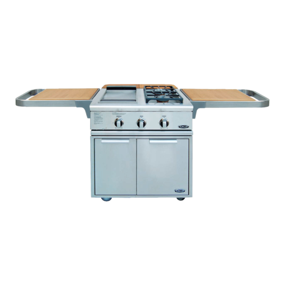
OUTDOOR APPLIANCE MODELS BFG-30G - All-Grill BFG-30BGD - Double Side Burner/Griddle BFG-30BS - Double Side Burner/Sink... -
Page 8: Before Using Your Appliance
- Cover hanger (2 pcs) - Burner caps (2 pcs) NOTE: If any of the listed items are missing, contact DCS at (888) 936-7872. Please be prepared with your Model #, Serial # and description of product you have purchased. -
Page 9: Installation
INSTALLATION LOCATING OUTDOOR APPLIANCE/BUILT-IN CLEARANCES LOCATION: When determining a suitable location, take into account concerns such as exposure to wind (If located in a windy area, a wind break must be provided to prevent poor burner performance or product damage.), proximity to traffic paths and keeping... - Page 10 Insulated jacket is not required for BFG-30BS Side Burner Sink Model. Use only the DCS insulated jacket (p/n #70859) which has specifically been designed and tested for this purpose. Review the detail...
-
Page 11: Built-In Construction Details
INSTALLATION BUILT-IN CONSTRUCTION DETAILS grill exhaust 12" (to combustible construction) 10-1/16" ZII ..Standard layout for non-combustible enclosure: WARNING! If installing grill into non-combustible enclosure, all combustible 22-3/4" construction must still outside the 12 inch clearance zone. If your island is made of stucco over... -
Page 12: Cart Assembly Instructions
INSTALLATION CART ASSEMBLY INSTRUCTIONS IMPORTANT: Read all instructions before you begin. Do not jump ahead or skip any step. CAUTION: Some parts have sharp edges; care must be taken when handling the various components avoid injury. Please read safety information provided in these instructions... - Page 13 INSTALLATION CART ASSEMBLY INSTRUCTIONS Step Link Carts Together (optional) link or more carts, following instructions must done first, using hardware provided, before installing modules.) To link your carts together - hand tighten 2 bolts, 4 washers, and 2 nuts on the front and back sides of the carts as shown in Fig.
- Page 14 INSTALLATION CART ASSEMBLY INSTRUCTIONS Step Outdoor Appliance Head Preparation First you will need to remove the angle brackets from the side of the unit and replace them with cart mount brackets (Fig. 06). Unit is shipped prepared for island installation. Install the bracket tab on both sides of the appliance...
- Page 15 INSTALLATION CART ASSEMBLY INSTRUCTIONS Position tabs on side bracket to fit into slots on the cart (be aware of pinch points)(Fig. 12-13). When complete, the leading ledge should sit flush on the top of the cart (no gap)(Fig. 14). Fig. 12 Fig.
-
Page 16: Cart Assembly Instructions
INSTALLATION CART ASSEMBLY INSTRUCTIONS Step 4 Gas Hookup - LP Make sure the cart assembly is stable. Open the tank drawer. Place the LP tank into location as shown in Fig. 17. Connect the regulator assembly to the tank connection with all appliances valves in the "OFF"... -
Page 17: Gas Hook-Up
INSTALLATION GAS HOOK-UP GAS REQUIREMENT Verify the type of gas supply to be used, either natural or LID,and make sure the marking on the appliance rating plate agrees with that of the supply. The rating plate is located on the bottom of the outdoor appliance. - Page 18 INSTALLATION GAS HOOK-UP LP GAS HOOK UP (TYPE 1 OR QCC1 REGULATOR): All outdoor appliances orificed for use with LP gas come equipped with a high capacity hose/regulator assembly for connection to a standard 20 lb. LP cylinder (Type 1). The LP tank is not included. Connection: 1/2"...
- Page 19 Built-in LPtank restraint must be installed prior to initial use of the grill. If you do not have one please contact DCS Customer Care at (888) 936-7872 for information on obtaining one. The following steps will illustrate...
-
Page 20: Gas Hook-Up
INSTALLATION GAS HOOK-UP STEP I Place the tank restraint in the island (Fig. 25). STEP 2 Locate the tank restraint in the island within the recommended area (Fig. 24 and 26). STEP Once located, secure to the bottom of the island using all eight hole locations provided... -
Page 21: Leak Testing
INSTALLATION LEAK TESTING - GRILL/GRIDDLE UNIT GENERAL: Although all gas connections on the outdoor appliance are leak tested at the factory prior to shipment, complete gas tightness check must be performed at the installation site due to possible mishandling shipment, or excessive pressure unknowingly... -
Page 22: Leak Testing
INSTALLATION LEAK TESTING - SIDE BURNER WARNING! Do not smoke while leak testing. Extinguish all open flames. Make a soap solution of one part liquid detergent, and one part water. Never test for leaks with an open flame. For LP units, check with a full cylinder. -
Page 23: Burner Adjustment
INSTALLATION BURNER ADJUSTMENT - GRILL/GRIDDLE UNIT Each outdoor appliance burner is tested and adjusted at the factory prior to shipment; however, variations in the local gas supply or a conversion from one gas type to another may make it necessary to adjust the burners. -
Page 24: Radiant Assembly
INSTALLATION RADIANT ASSEMBLY RADIANT ASSEMBLY INSTALLATION: Unpack ceramic rods and remove radiant (Fig.37) from the unit. Unlock radiant end cap by pushing it up with two fingers (Fig. 38). Place 18 ceramic rods on the radiant (Fig. 39). Lock radiant end cap (Fig. -
Page 25: Sink
INSTALLATION SINK FAUCET INSTALLATION Attach the faucet to the sink as shown in Fig. 42 and 42a. CAUTION: Finger tight first, then use a 1"wrench. Faucet stem Valve Fig. 42 2. Insert drain plug into the drain hole Fig. 43. Rubbergasket Lock washer Fig. -
Page 26: Side Shelf (Optional)
INSTALLATION SIDE SHELF (Optional accessory) Attach Side Shelf Accessory on Either Side. Side shelf Model CAD-SK can be installed with the head already on the cart. Screw shoulder bolts (2) into the bottom screw holes on the side of the cart only (Fig. 44 and 45). Tighten with 5/32 Allen wrench. -
Page 27: Side Shelf (Optional)
INSTALLATION SIDE SHELF (Optional accessory) Place shelf in the up position and check that it is level. If shelf is not level, adjust side shelf set screw. Set screws can be adjusted using a 3/32 Allen wrench (Fig. 50). Turn the Allen wrench clockwise to raise the shelf. -
Page 28: Using The Grill
USING THE GRILL LIGHTING INSTRUCTIONS Note: Remove the top grill cover before lighting. Turn all knobs to "OFF': Turn the main gas supply on. If you smell gas, shut- off gas supply and call for service. Grill Lighting Instructions: The grill knob is connected to the electronic ignition... - Page 29 USING THE GRILL IMPORTANT - Using the Grill: Grilling requires high heat for searing and proper browning. Most foods are cooked between "MEDIUM"and "LOW" heat setting for the entire cooking time. However, when cooking large pieces of meat or poultry, it may be necessary to turn the heat to a lower setting...
-
Page 30: Using The Side Burner
USING THE SIDE BURNER LIGHTING INSTRUCTIONS First remove the cover and any cooking utensils from the burner grate. Check to see if the burner cap is on correct. Push, turn and hold the control knob in at the "HI" position until the burner is lit or 4 seconds pass (Fig. -
Page 31: Using The Griddle
USING THE GRIDDLE The griddle is made from stainless steel, highly polished to provide smooth cooking surface. It is normal for it to darken with use as oils GRIDDLE FLUE cook onto the surface to provide a nonstick base or "seasoning". COVER Since the griddle is made from... -
Page 32: Lighting Instructions
USING THE GRIDDLE LIGHTING INSTRUCTIONS Push in and turn griddle control knob to "HI" position. Pushing control knob in activates the ignition module produces repeated sparking at burner igniter. Holding control knob in also opens the integral safety valve used for this section and starts the flow of gas to burner. -
Page 33: Using The Sink
USING THE SINK The sink is available to provide water to your Liberty collection. The faucet is in the "on" position when the lever is turned up (Fig. 58). The faucet is "off" when in the down position as shown in Figure 59. -
Page 34: Care & Maintenance
CARE AND MAINTENANCE BATTERY REPLACEMENT: Remove drip pan. Pull battery downward (This may require use of pliers.) Re-install upward and push to snap in - Fig. 60. (Polarity is shown in Fig. 61). Note: Battery condition should be checked at least once a year. Fig.60 Fig. - Page 35 CARE AND MAINTENANCE If something has spilled into the trays it should be cleaned up as soon as possible to prevent "baked on"food soil. Grease from the griddle or the outdoor appliance drains through the drain tube (Fig. 64) into the tray and liner below.
- Page 36 CARE AND MAINTENANCE ORIFICE CLEANING: With the burner removed, remove the orifice and shine a flashlight through the opening to ensure there is no blockage. Use a needle to clear any debris. Be extremely careful not to enlarge the hole or break off the needle. See Fig.
-
Page 37: Care & Maintenance
CARE AND MAINTENANCE caps are porcelain enamel, follow the directions above that were given for the burner grates. A bristle brush can be used to clean out the toothed burner ports, if necessary. After cleaning, it is important to make sure the location pins on the bottom side of the port ring are properly... -
Page 38: Troubleshooting
Only authorized agencies can perform warranty service. Call DCS Customer Care at (888) 936-7872. PROBLEM WHAT TO DO Outdoor appliance won't light Is the gas supply... -
Page 39: Side Burner
TROUBLESHOOTING - SIDE BURNER PROBLEM WHAT TO DO Burner won't light when the Remove the burner grate. Push in the control knob and ignition is pushed. listen to the electrode while engaging the ignition. There should be a spark from the electrode. When spark jumps, it makes a ticking... -
Page 40: Service
SERVICE HOW TO OBTAIN SERVICE: For warranty service, please contact your local service provider or DCS Customer Care Representative (888) 936-7872. Before you call, please have the following information ready: Model Number (can be found on the inside, right side panel behind the drip pan handle. -
Page 41: Warranty
WARRANTY LIMITED WARRANTY When you purchase a new DCS Outdoor Appliance by Fisher & Paykel, you automatically receive a One Year Limited Warranty covering parts and labor for the entire product, and a Five Year Limited Warranty on all stainless... -
Page 42: Warranty
Fisher & Paykel Appliances Inc. is a leading manufacturer of premium quality cooking and specialty appliances under the Fisher & Paykel and DCS brands. - Page 43 NOTES...
- Page 45 I'exp6dition. En cas de dommages, contacter le transporteur et entamer une d6claration pour dommage. DCS by Fisher & Paykel n'est en aucun cas responsable des dommages pendant I'exp6dition. Ne pas jeter le mat#riau d'emballage (boite, palette, sangles) avant d'avoir inspect# I'unit#.
- Page 46 TABLE DES MATli::RES MESURES DE S¢CURIT¢ ET DE PRECAUTION MODELES D'APPAREILS D'EXTCRIEUR AVANT D'UTILISER L'APPAREIL INSTALLATION 9-10 Emplacement de I'appareil d'ext6rieur et des d6gagements D6tails d'une construction int6gr6e 12-16 Instructions de montage de chariot 17-20 Branchement de gaz Test de d6tection des fuites 21-22 R6glage des brOleurs...
- Page 47 MESURES DE SI CURITI ET DE PRI CAUTION IMPORTANTE CONSIGNE DE SECURITE! Certains fournisseurs de propane liquide peuvent remplir les bonbonnes de propane liquide de I'appareil d'ext_rieur au-dela de leur capacitY. Ce trop-plein peut crier une situation dangereuse. IMPORTANTE CONSlGNE DE SECURITE! Assurez-vousde retirer tousles couvercles du gril, de la plaque chauffante ou des brQleurs lat_raux avant d'allumer ou d'utiliser I'appareil.
- Page 48 MESURES DE S¢:CURIT¢:ET DE PRO:CAUTION Ne rangez pas d'objets pouvant int_resser les enfants autour ou en dessous d'appareil d'ext_rieur, dans le chariot ou une enceinte de ma(;onnerie. Ne laissez jamais les enfants ramper _ I'int_rieur d'un chariot ou d'une enceinte. Ne laissez jamais des v_tements, gants ou autres mat_riaux inflammables...
- Page 49 MESURES DE S¢CURIT¢ ET DE PRECAUTION EMPLACEMENT D'APPAREIL D'EXTI_RIEUR FLUXD'EVENT DE SORTIE EVACUATIONDU GRIL FLUX D'AIR PRI_FERE BROLEUR Si vous utilisez les brOleurs lat_raux, servez-vous toujours de casseroles ) fond plat assez grandes pour couvrir brOleur lateral. Ajustez la flamme pour qu'elle ne chauffe que le fond...
- Page 50 MESURES DE SC:CURIT¢:ET DE PRO:CAUTION Ne d_placez pas I'appareil durant son utilisation. Cet appareil est con_u pour un usage en plein air uniquement ! Ne faites pas fonctionner dans des endroits clos. Ce qui pourrait entra_ner une accumulation de monoxyde de carbone susceptible de provoquer...
- Page 51 MODf::LES D'APPAREILS D'EXTI_RIEUR BFG-30G - Tout gril BFG-30BGD - BrQleurs lat_raux double et Plaque chauffante BFG-30BS - BrQleurs lat_raux double et I_vier...
- Page 52 - Capuchon de br01eur (2) REMARQUE Si un des articles indiqu_s manque, contactez DCS au (888) 936-7872. Veuillez avoir le num_ro de module, num_ro de s_rie et la description du produit dont vous avez fait I'achat a pottle de la main.
- Page 53 INSTALLATION EMPLACEMENT DE L'APPAREIL D'EXTI RIEUR ET DES DI GAGEMENTS EMPLACEMENT Pour d_terminer un emplacement appropri_, vous devez tenir compte de plusieurs _l_ments : exposition au vent (si I'appareil est situ_ dans une zone venteuse, un coupe-vent dolt _tre fourni pour _viter un mauvais fonction-...
- Page 54 6vier/br01eurs lat6raux BFG-30BS. Utilisez uniquement une enveloppe isol6e DCS ayant 6t6 con(_ue et test6e sp6cialement & cette fin. Analysez le sch6ma d6taill6 (Fig. 03) et tenez compte des dispositions & prendre pour le branchement...
- Page 55 INSTALLATION DETAILS D'UNE CONSTRUCTION INTCGRCE 6vacuation du gril ....C30 ,n5s t cr u m_i20 p 0 0(dm6bgasl iebme_ntavec une _Fond de la bride de soutien 25,56 cm/lO 1/16po 0000000 5,08 cm/ 57,79 cm/22 3/4po ...... 1,91 cm/3/4 2 po 64,77 cm/25 1/2 po ..........
- Page 56 INSTALLATION INSTRUCTIONS DE MONTAGE DE CHARIOT IMPORTANT: Lisez toutes les instructions avant de commencer, levitez de sauter des 6tapes. ATTENTION : Certaines pi6ces ont des bords coupants; faites attention Iorsque vous manipulez les diffdrents composants pour dviter de vous blesser. Veuillez lire les consignes de sdcurit_ de ce manuel avant de commencer I'assemblage.
- Page 57 INSTALLATION INSTRUCTIONS DE MONTAGE DE CHARIOT I_tape Regroupement chariot option) (Pour regrouper deux chariots plus, procddez instructions suivantes premier, _ I'aide de la visserie fournie, avant d'installer les modules supdrieurs.) Pour regrouper les chariots - serrez _ la main 2 boulons, 4 rondelles et 2 _crous sur le devant et I'arri_re...
- Page 58 INSTALLATION INSTRUCTIONS DE MONTAGE DE CHARIOT I tape Prdparation de la t_te de I'appareil d'extdrieur 1. II vous faut d'abord retirer les _querres du c6t_ de I'appareil et les remplacer par les supports de fixation du chariot (Fig. 06). L'appareil est exp_di_ pr_par_ pour une installation...
- Page 59 INSTALLATION INSTRUCTIONS DE MONTAGE DE CHARIOT 3. Positionnez les languettes sur le support lateral pour rentrer dans les fentes sur le chariot (faites attention points de pincement) (Fig. 12 -13). Une lois termin_, la piece d'appui doit affleurer le haut du chariot (sans appui) (Fig.
- Page 60 INSTALLATION INSTRUCTIONS DE MONTAGE DE CHARIOT I_tape 4 Branchement du gaz - Propane Assurez-vous que I'ensemble de chariot est stable. Ouvrez le tiroir de la bouteille. Placez la bouteille de propane comme I'indique la Fig. 17. Raccordez I'ensemble du r_gulateur _ la connexion de bouteille avec toutes...
- Page 61 _ la norme ANSI Z223.1 du National Fuel Gas Code. Les kits de conversion au gaz sont disponibles aupr_s de I'Centre de service _ la clientele DCS. Au moment de commander un kit de conversion au gaz, ayez sous la main le num6ro de module...
- Page 62 INSTALLATION BRANCHEMENT DU GAZ BRANCHEMENT DU PROPANE (RIeGULATEUR DE TYPE I OU QCCl) Tousles appareils d'ext_rieur dont les orifices sont pr_vus pour du propane sont _quip_s d'un tuyau et d'un r_gulateur de haute capacit_ pouvant _tre connect_s & une bouteille standard de propane de 9 kg (20 Ib) (Type I).
- Page 63 242232, avant d'utiliser le gril pour la premiere fois. Si vous n'avez pas ce dispositif, veuillez contacter le Service _ la clientele DCS en composant le (888) 936-7872 pour en obtenir Les _tapes suivantes illustrent la mani_re de trouver...
- Page 64 INSTALLATION BRANCHEMENT DU GAZ STEP I Placez le dispositif de retenue de bouteille dans l'ilot (Fig. 25). STEP 2 Situez le dispositif de retenue de bouteille dans l'ilot _ l'int_rieur la zone recommand_e (Fig. 24 et 26). STEP 3 Une lois situS, fixer sur le bas de I'ilot _ I'aide des huit emplacements de trous pr_vus sur le dispositif de retenue.
- Page 65 INSTALLATION TEST DE DETECTION DES FUITES - UNITe DE GRILLE ET DE PLAQUE CHAUFFANTE GI_NI_RALITI_S Bien que toutes les connexions de gaz du gril soient test_es en usine avant I'exp_dition, une v_rification complete doit _tre effectu_e sur le site d'installation, pour s'assurer qu'il n'y a pas de fuites, au cas o0 I'appareil...
- Page 66 INSTALLATION TEST DE DETECTION DES FUITES - BRULEUR LATERAUX AVERTISSEMENT! Ne fumez loas pendant le test. I_teignez toute flamme rive. Pr_parez une solution savonneuse compos6e _ moiti_ de d_tergent liquide et _ moiti_ d'eau. Ne v_rifiez jamais la presence de fuites pros d'une flamme vive.
- Page 67 INSTALLATION RI GLAGE DU BRULEUR DU GRIL - UNITIES DE GRILLE ET DE PLAQUE CHAUFFANTE Chaque br01eur du gril est test6 et r6g16 en usine avant d'etre exp6di6; toutefois, des variations au niveau I'alimentation en gaz locale ou de la conversion d'un gaz _ un autre peut n6cessiter un nouveau...
- Page 68 INSTALLATION INSTALLATION DE L'ENSEMBLE DU RADIANT INSTALLATION DE L'ENSEMBLE DU RADIANT 1. D_ballez les tiges en c_ramique et retirez le radiant (Fig. 37) de I'appareil. D_verrouillez le couvercle du radiant en le poussant de deux doigts (Fig. 38). Placez 18 tiges en c_ramique sur le radiant (Fig.
- Page 69 INSTALLATION EVIER INSTALLATION DES ROBINETS Attachez le robinet _ l'_vier comme l'indiquent les Fig. 42 et 42a. ATTENTION : Serrez d'abord a la main puis utilisez une cl_ de I". Tige de robinet Valve Fig. 42 2. Ins6rez la bonde dans l'orifice d'6vacuation Fig.
- Page 70 INSTALLATION TABLETTE LATI RALE (accessoire en option) Attachez I'accessoire de tablette lat_rale d'un c6t_ ou de I'autre. II est possible d'installer la tablette lat_rale ModUle CAD-SK avec la t_te d_j_ sur le chariot. Vissez (2) boulons _ 6paulement dans les orifices pour vis inf6rieurs sur le c6t6 du chariot uniquement...
- Page 71 INSTALLATION TABLETTE LATI RALE (accessoire en option) Placez la tablette en position relev_e et v_rifiez qu'elle est de niveau. Si la tablette n'est pas de niveau, ajustez la vis de r_glage de la tablette lat_rale. Pour ajuster les vis de r_glage, utilisez une cl_ Allen 3/32 (Fig.
- Page 72 UTILISATION DU GRIL INSTRUCTIONS D'ALLUMAGE Remarque Retirez le couvercle du gril sup_rieur avant d'allumer le gill Mettez tous les boutons sur _ OFF _. Ouvrez I'alimentation gaz. Si vous sentez une odeur de gaz, fermez le gaz et appelez le service technique. Instructionsd'allumagedugril: Le bouton du gril est raccord_...
- Page 73 UTILISATION DU GRIL IMPORTANT Utilisation du gril : La cuisson sur gril exige un feu vif pour r6tir les aliments et les braiser correctement. La plupart des aliments sont cuits _ feu mod_r_ pendant tout le temps de cuisson. Cependant, pour cuire de gros morceaux de viande ou de volaille,...
- Page 74 UTILISATION DU DRULEUR LATI RAL INSTRUCTIONS D'ALLUMAGE Commencez par retirer le couvercle et les ustensiles de cuisson de la grille des br01eurs. V_rifiez que le capuchon de brQleur est mis correctement. Enfoncez, tournez et maintenez le bouton de r_glage en position <_HI _ jusqu'_ ce que le brQleur soit allum_ ou que 4 secondes...
- Page 75 UTILISATION DE LA PLAQUE CHAUFFANTE La plaque chauffante est fabriqu_e en acier inoxydable, polie _tincelante, pour fournir une surface de cuisson lisse. II est normal qu'elle fonce CAPUCHON DE CONDUIT DE I'usage avec les huiles qui cuisent sur la surface pour fournir une base PLAQUE CHAUFFANTE...
- Page 76 UTILISATION DE LA PLAQUE CHAUFFANTE INSTRUCTIONS D'ALLUMAGE Enfoncez et tournez le bouton de r6glage de la plaque chauffante en position <_ HI >>. E nfoncer le bouton r6glage activera le module d'allumage et produira des 6tincelles r6p6t6es _ I'allumeur du br_leur. Maintenir bouton de r6glage...
- Page 77 UTILISATION DE L'f:VIER L'6vier est disponible pour fournir de I'eau _ la Collection Liberty. Le robinet est en position <<on >>Iorsque levier est relev_ (Fig. 58). Le robinet est en position << off >_ Iorsqu'il est abaiss_ comme I'indique la Figure 59. Fig.
- Page 78 ENTRETIEN ET NETTOYAGE REMPLACEMENT DE LA PILE : Retirez le ramasse-gouttes. Tirez la pile vers le bas (servez-vous d'une pince aubesoin). Remettez-la en place vers le haut et poussez jusqu'_ entendre un d_clic, Fig. 60. (La polarit_ est indiqu_e _ la Fig. 61.) Remarque V_fifiez I'_tat de la pile au moins une fois par an.
- Page 79 ENTRETIEN ET MAINTENANCE Nettoyez tout d6bordement dans les plateaux aussi rapidement que possible pour 6viter des taches d'aliments <<incrust6s >>.Lagraissede_aplaquechauffante_ude_'apparei_d'ext6rieurs'6c_u_epar_etubedevidange (Fig. 63) dansleplateauetlerev6tementendessous. Nelaissezpaslagraisses'accumulerdansleplateaucar ellepeut_treun risqued'incendie. Nettoyezletubeetleplateaud_squ'ilssont refroidis. Nettoyez_l'eau chaude savonneuse. Pour le tube, utilisez un goupillon savonneux. Assurez-vous que le r6cipient _ graisse est en placelorsdu nettoyagedutubedevidange.
- Page 80 ENTRETIEN ET MAINTENANCE NETTOYAGE DE L'ORIFICE Le brOleur _tant retire, enlevez I'orifice et inspectez I'ouverture avec une lampe de poche pour vous assurer qu'elle n'est pas bloqu_e. D_gagez les d_bris _ I'aide d'une aiguille. Faites extr_mement attention de ne pas _largir trou ou de casser I'aiguille.
- Page 81 ENTRETIEN ET MAINTENANCE chaque d_bordement important ou si la flamme ne devient pas bleue. Assurez-vous que tous les boutons brOleurs sont en position _ OFF >> avant d'essayer de nettoyer les brOleurs. Les brOleurs ont _t_ con(;us pour _tre faciles _ nettoyer. Une fois la grille et les brOleurs refroidis, retirez...
- Page 82 Seuls les centres de service agr_s peuvent entreprendre un service sous garantie. Appelez le centre de service _ la clientele DCS au (888) 936-7872. PROBLEME SOLUTION L'appareil d'ext6rieur La provision de gaz est-il allum_e? s'allumera pas Iorsque Assurez-vous que I'appareil d'ext_rieur est froid.
- Page 83 DI PANNAGE - BRULEUR LATI RAL PROBLEME SOLUTION Le brOleur ne s'allume Retirez la grille du brOleur. Enfoncez le bouton de r_glage _tant Iorsqu'on enfonce le bouton sur _ OFF _, _coutez I'_lectrode tout en enfon(_ant le bouton d'allumage. d'allumage. Vous devriez entendre une _tincelle...
- Page 84 Si un probl_me n'est pas r_solu _ votre enti_re satisfaction, veuillez communiquer avec nous par courrier. lecrivez-nous _ I'adresse suivante Fisher & Paykel Appliances, Inc. Attention : DCS Customer Care 5900 Skylab Road Huntington Beach, CA 92647 letats-Unis www.dcsappliances.com...
- Page 85 GARANTIE GARANTIE LIMITI_E Lorsque vous faites I'achat d'un nouvel appareil d'ext_rieur DCS de Fisher & Paykel, vous b_n_ficiez automa- tiquement d'une garantie limit_e d'un an couvrant les pi_ces et la main d'oeuvre pour I'int_gralit_ du produit, d'une garantie limit_e de cinq ans sur les br01eurs principaux...
- Page 86 & I'autre. Fisher & Paykel Appliances inc. est un fabricant de pointe d'appareils de cuisson et d'appareils specialists, sous les marques Fisher & Paykel et DCS.
- Page 87 REMARQUE...
- Page 88 REMARQUE...
- Page 89 REMARQUE...
Need help?
Do you have a question about the BFG-30BS and is the answer not in the manual?
Questions and answers