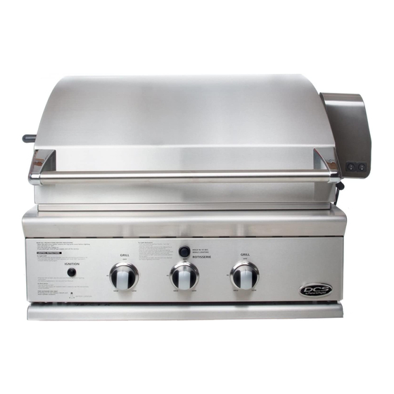
DCS BGB30-BQR Series Use And Care Manual
The professional 30" bgb series grill
Hide thumbs
Also See for BGB30-BQR Series:
- Use and care manual (80 pages) ,
- Brochure & specs (2 pages) ,
- Specifications (2 pages)
Table of Contents
Advertisement
Available languages
Available languages
Quick Links
Download this manual
See also:
Use and Care Manual
Advertisement
Table of Contents

Related Manuals for DCS BGB30-BQR Series


Summary of Contents for DCS BGB30-BQR Series
- Page 2 If any damage is detected, call the shipper and initiate a damage claim. DCS by Fisher & Paykel is not responsible for shipping damage. DO NOT discard any packing material (box, pallet, straps) until the unit has been inspected.
-
Page 3: Table Of Contents
CONTENTS SAFETY PRACTICES & PRECAUTIONS GRILL MODELS INSTALLATION Locating Grill/Built-in Clearances Built-in Construction Details 10-11 12-15 Cart Assembly Instructions 16-19 Gas Hook-up Leak Testing Burner Adjustment Radiant Assembly Installer Checklist USING THE GRILL Lighting Instructions 25-26 Grilling USING THE ROTISSERIE 27-30 CARE &... -
Page 4: Safety Practices & Precautions
SAFETY PRACTICES & PRECAUTIONS IMPORTANT SAFETY NOTICE! Certain Liquid Propane dealers may fill liquid propane cylinders for use in the grill beyond cylinder filling capacity. This"Overfilling" may create a dangerous condition. "Overfilled"tanks can build up excess pressure. As a safety device, the tank pressure relief valve will vent propane... - Page 5 SAFETY PRACTICES & PRECAUTIONS • After a period of storage or non-use (such as over the winter), the gas grill should be checked for gas leaks, deterioration, proper assembly, and burner obstructions before using. • Never let clothing, pot holders or other flammable materials come in contact...
-
Page 6: Safety Practices & Precautions
SAFETY PRACTICES & PRECAUTIONS When using the side burners always use flat bottomed pans which are large enough to cover the side burner. Adjust the flame so that it heats only the bottom of the pan to avoid ignition of clothing. Position handles inward... -
Page 7: Grill Models
GRILL MODELS BGB30-BQR... -
Page 8: Installation
INSTALLATION LOCATING GRILL/BUILT-IN CLEARANCES LOCATION: When determining a suitable location take into account concerns such as exposure to wind, proximity to traffic paths and keeping any gas or electrical supply lines as short as possible and away from heat sources. Locate the grill only in a well ventilated area. - Page 9 INSTALLATION LOCATING GRILL/BUILT-IN CLEARANCES Clearances to Non-Combustible Construction*: A minimum of 3" clearance from the back of the grill to non-combustible construction is required for the purpose of allowing the lid to open fully. It is desirable to allow at least 6" rear and side clearance to non-combustible construction above the cooking...
-
Page 10: Locating Grill/Built-In Clearances
Insulated jackets are available from your dealer. Use only the DCS insulated jacket which has specifically been designed and tested for this purpose. Review the detail drawing shown (Fig. 04) and take into account... - Page 11 INSTALLATION BUILT-IN CONSTRUCTION DETAILS grill exhaust 3" (to non-combustible construction minimum lid clearance) 1 2" (to combustible construct support flange 10-1/16" 22-3/4 ..3/4" 25-1/2 ............Standard layout for non-combustible enclosure: Layout for insulated jacket only - combustible enclosure: NOTE: If using a backguard NOTE: If using a backguard apron or rear apron or rear wall, locate wall, locate electrical service on the right...
-
Page 12: Built-In Construction Details
INSTALLATION BUILT-IN CONSTRUCTION DETAILS Access Drawers Access Doors Cutout dimensions Cutout dimensions Vent* ..Vent Vent* Optimal support locations Cutout for Access Doors FIG. 06 FIG. O5 NOTE: The cutout of each corner should be 90°angle in order for the access drawers NOTE: The cutout of each corner should... -
Page 13: Cart Assembly Instructions
INSTALLATION CART ASSEMBLY INSTRUCTIONS IMPORTANT! Read all instructions before you begin. Do not jump ahead or skip any step. CAUTION! Some parts have sharp edges; care must be taken when handling the various components to avoid injury. Please read safety information provided in these instructions before beginning assembly. - Page 14 INSTALLATION CART ASSEMBLY INSTRUCTIONS STEP I Attach Side Shelf on the Right Side (left side is optional side burner location) Attach shelf to right side of the cart using 1/4-20 nuts and bolts provided [leave out (1) bolt front side as shown below].
- Page 15 INSTALLATION CART ASSEMBLY INSTRUCTIONS FIG. 11 Grill head should rest over rear cart FIG. 10 Lift grill over rear flange of cart (be FIG. 12 Secure grill to rear of cart with (2) aware of pinch points). flange as shown above. phillips-head screws provided (10-24 x I/2").
-
Page 16: Cart Assembly Instructions
INSTALLATION CART ASSEMBLY INSTRUCTIONS STEP 5 Side tray adjustment 1. Take the tray and place it onto the handle at a upright position. Make sure the tray sits snugly around the handle. 2. Then tighten the rest of the loose bolts that were not tightened in Step 1. -
Page 17: Gas Hook-Up
INSTALLATION GAS HOOK-UP GAS REQUIREMENT Verify the type of gas supply to be used, either natural or LP, and make sure the marking on the appliance rating plate agrees with that of the supply. The rating plate is located underneath the unit bottom. - Page 18 INSTALLATION GAS HOOK-UP Connection: I/2" NPT male with a 3/8" Flare adapter (included). LP Hose with a quick disconnect and fittings included. Operating pressure: 11.0" W.C. CAUTION! Before connecting LP tank to regulator, check that all grill burners, side burners, and rotisserie valves are in the OFF position and open grill lid.
- Page 19 Built-in LPtank restraint must be installed prior to initial use of the grill. If you do not have one please contact DCS Customer Care at (888) 936-7872 for information on obtaining one. The following steps will illustrate...
-
Page 20: Gas Hook-Up
INSTALLATION GAS HOOK-UP STEP I Place the tank restraint in the island (Fig. 25). STEP 2 Locate the tank restraint in the island within the recommended area (Fig. 24 and 26). STEP Once located, secure to the bottom of the island using all eight hole locations provided... -
Page 21: Leak Testing
INSTALLATION LEAK TESTING GENERAL: Although all gas connections on the grill are leak tested at the factory prior to shipment, a complete tightness check must be performed at the installation site due to possible mishandling in shipment, or excessive pressure unknowingly being applied to the unit. -
Page 22: Burner Adjustment
INSTALLATION BURNER ADJUSTMENT GRILL BURNER AIR ADJUSTMENT: Each grill burner is tested and adjusted at the factory prior to shipment; however, variations in the local gas supply or a conversion from one gas type to another may make it necessary to adjust the burners. -
Page 23: Radiant Assembly
INSTALLATION RADIANT ASSEMBLY RADIANT ASSEMBLY INSTALLATION: Unpack ceramic rods and remove radiant (Fig. 34) from the unit. Unlock radiant end cap by pushing it up with two fingers (Fig. 35). Place 18 ceramic rods on the radiant (Fig. 36). Lock radiant end cap (Fig. -
Page 24: Installer Checklist
NOTE: If any of the listed items are missing, contact DCS at (888) 936-7872. Please be prepared with your Model #, Serial # and description of item(s) that are missing. Tag location of... -
Page 25: Using The Grill
USING THE GRILL LIGHTING INSTRUCTIONS TO LIGHT THE GRILL BURNER: Open the grill lid before lighting. Turn all knobs to "OFF': Turn the main gas supply on slowly. If you smell gas, shut-off gas supply and call for service. Push and hold the ignition button, turn the selected burner... -
Page 26: Grilling
USING THE GRILL GRILLING GRILL: Each grill section consists of a large stainless steel burner, stainless steel heat baffles, a series of ceramic rods encased in a stainless steel radiant, and a stainless steel heat retaining grate. Each burner is rated at 25,000Btu/hr. -
Page 27: Grilling
USING THE GRILL GRILLING IMPORTANT - Using the Grill: To season the grates, pour a tablespoon of vegetable oil on a soft cloth and rub on both sides of the grates. Only a light coating is needed and some smoke may be visible during the preheating. -
Page 28: Using The Rotisserie
USING THE ROTISSERIE The grill rotisserie system is designed to cook items from the back using infrared heat. The location of the burner allows the placement of the rotisserie basting pan (included) beneath food to collect juices and drippings for basting and gravy. - Page 29 USING THE ROTISSERIE WARNING! Never have the grill burners (bottom burners) on during Rotisserie cooking. It will burn your meat and make it very dry. Use only one section at a time, grill or rotisserie. PREPARATION Recommended: Dental floss or butcher string, scissors, broiler pan (bottom...
- Page 30 USING THE ROTISSERIE TO LIGHT THE ROTISSERIE BURNER BEFORE COOKING: The location of the rotisserie burner makes it more susceptible to strong wind conditions, more so than the protected grill burners. For this reason, you should avoid operating the rotisserie during windy conditions.
-
Page 31: Using The Rotisserie
USING THE ROTISSERIE COOKING ON ROTISSERIE 1. Place prepared rod into motor, lay across to other side in groove (Fig. 48). 2. Verify placement as shown in Fig. 49. Ignite burner, start rotisserie motor, and keep on rotisserie valve on "high"for cooking all meats on the rotisserie. -
Page 32: Care & Maintenance
CARE AND MAINTENANCE BATTERY REPLACEMENT: Remove drip pan. Open cart door (on cart model only) Pull battery downwards (this may require use of pliers). Re-install upward and push to snap - Fig. 52. (polarity is shown in Fig. 53). Note: Battery condition should be checked at least once a year. -
Page 33: Care & Maintenance
CARE AND MAINTENANCE direction of the grain. Specks of grease can gather on the surfaces of the stainless ELECTRODE (KEEP CLEAN) steel and bake on to the surface and give the appearance of rust. For removal an abrasive pad (Scotch Brite is good) in conjunction with a stainless steel cleaner. -
Page 34: Troubleshooting
Only authorized agencies can perform warranty service. Call DCS Customer Care at (888) 936-7872. GRILL WON'T LIGHT WHEN THE IGNITION BUTTON IS PUSHED: 1. Is the gas supply turned Ensure the grill is cool. -
Page 35: Service
SERVICE HOW TO OBTAIN SERVICE: For warranty service, please contact your local service provider or DCS Customer Care Representative (888) 936-7872. Before you call, please have the following information ready: Model Number (can be found on the inside, right side panel behind the drip pan handle. -
Page 36: Warranty
WARRANTY LIMITED WARRANTY When you purchase a new DCS Grill by Fisher & Paykel, you automatically receive a One Year Limited Warranty covering parts and labor for the entire product, and a Five Year Comprehensive Warranty covering burners, grill radiant assemblies, and drip pans. -
Page 37: Warranty
Fisher & Paykel Appliances Inc. is a leading manufacturer of premium quality cooking and specialty appliances under the Fisher & Paykel and DCS brands. - Page 39 A L'INTENTION DE NOS CLIENTS Nous vous remercions d'avoir choisi ce gril de la s_rie professionnelle <<BGB >> de DCS. Nous avons con(_u ce Manuel d'utilisation et d'entretien pour expliquer les fonctions uniques de ces appareils. Ce manuel contient informations...
- Page 40 TABLE DES MATli::RES MESURES DE SIeCURITIe ET DE PRIeCAUTION MODItLES DE GRIL INSTALLATION 8-10 Emplacement du gril et des d_gagements 11-12 D_tails d'une construction int_gr_e 13-16 Instructions de montage de chariot 17-20 Branchement du gaz Test de d_tection des fuites R_glage du br01eur du gril L'ensemble du radiant...
- Page 41 MESURES DE SI CURITI ET DE PRI CAUTION IMPORTANTE CONSIGNE DE SECURITE! Certains fournisseurs de propane liquide peuvent remplir les bonbonnes de propane liquide du gril au-dela de leur capacitY. Ce trop-plein peut crier une situation dangereuse. Une accumulation de pression peut effet se produire dans les bouteilles trop remplies.
- Page 42 MESURES DE SI CURITI ET DE PRI CAUTION Ne rangez pas d'objets pouvant int_resser les enfants autour ou en dessous du gril, dans le chariot ou une enceinte de ma(_onnerie. Ne laissez jamais les enfants ramper _ I'int_rieur d'un chariot ou d'une enceinte.
- Page 43 MESURES DE SC:CURIT¢:ET DE PRO:CAUTION EMPLACEMENT DU GRIL FLUX D'EVENT DE SORTIE EVACUATION DU GRIL vent qui frappe Si le vent est un le gril pendant utilisation, particu- probl_me, li_rement les vents soufflant dans ou : po rain. faut ajouter sur cet espace de coupe-vent.
- Page 44 MESURES DE SC:CURIT¢:ET DE PRO:CAUTION • Ayez un extincteur de classe ABC _ port_e de la main - ne tentez jamais d'_teindre un incendie de graisse avec de I'eau ou d'autres liquides. • Pour _viter route brOlure Iors de la cuisson, utilisez des outils de barbecue...
- Page 45 MODi::LES DE GRIL BGB30-BQR...
- Page 46 INSTALLATION EMPLACEMENT DU GRIL ET DES DCGAGEMENTS EMPLACEMENT Pour d_terminer un emplacement appropri_, vous devez tenir compte de plusieurs _l_ments : exposition au vent, proximit_ de chemins de circulation, n_cessit_ de garder les conduites d'alimentation en gaz ou _lectrique plus court possibleet_l'_cartdetoutesourcedechaleur.
- Page 47 INSTALLATION EMPLACEMENT DU GRIL ET DES DI GAGEMENTS Espaces de d_gagement pour construction combustible Pr6voyez une distance de 7,6 cm (3 po) minimum entre I'arri_re du gril et la construction non combustible afin de pouvoir ouvrir le couvercle compl&tement. II est conseill6 de pr6voir au moins 15,3 cm (6 po) de d6gagement...
- Page 48 INSTALLATION EMPLACEMENT DU GRIL ET DES DI GAGEMENTS Espaces de d_gagement pour une construction combustible 76,2 cm/30 po 30,5 cm/. 30,5 cm/ 12po rain.) 12 po _vacuation rnin. du gril 67,31 cm/26 1/2 po _i A 30,5 cm/12 po (degagement rain.
- Page 49 INSTALLATION DETAILS D'UNE CONSTRUCTION INTCGRCE evacuation du gril ..po (d@gag ..t rain.pour _ 7,6 cm/3 / couvercle avec une construction combustible) | 30,5 cm/12 po (degagement avec une 34,93 cm/ 13 3/4 construction combustible) 25,56 cm/101/16po 2 po Disposition standard pour une enceinte...
- Page 50 INSTALLATION DETAILS D'UNE CONSTRUCTION INTEGREE LES TIROIRS - DIMENSIONS DES DECOUPES PORTES D'ACCES - DIMENSIONS DES DECOUPES ..Verlt _ Vent* ..Optimal support Iocatiorts D_coupe pour portes d'acc_s FIG. 06 FIG. 05 REMARQUE: La d_coupe de chaque coin doit _tre d'un angle REMARQUE: La d_coupe...
- Page 51 INSTALLATION INSTRUCTIONS DE MONTAGE DE CHARIOT Important! Lisez toutes les instructions avant de commencer. Cvitez de sauter des _tapes. MISE EN GARDE! Certaines pi_ces ont des bords coupants; faites attention Iorsque vous manipulez les diffdrents composants pour _viter de vous blesser. Veuillez lire les consignes de s_curit_ de ce manuel avant de commencer I'assemblage.
- Page 52 INSTALLATION INSTRUCTIONS DE MONTAGE DE CHARIOT I_TAPE 1 Fixez la tablette lat_rale sur le c6t_ droit (le c6t_ gauche est I'emplacement du br_leur lateral en option) Fixez la tablette au c6t6 droit du chariot _ I'aide d'6crous et de boulons 1/4-20 [laissez de c6t6 (1) boulon I'avant tel qu'indiqu6...
- Page 53 INSTALLATION INSTRUCTIONS DE MONTAGE DE CHARIOT FIG. 10 Placez le gril par-dessus la bride FIG. 11 La t_te du gril doit reposer par- FIG.I 2 Fixez le gril & la partie arri_re du chariot dessus la bride arri_re du chariot tel arriere du chariot (faites attention aux points l'aide de (2) vis phillips fournies...
- Page 54 INSTALLATION INSTRUCTIONS DE MONTAGE DE CHARIOT I_TAPE 5 R6glage du plateau lat6ral Saisissez le alateau et placez-le sur la poign6e en position verticale. Assurez-vous que le plateau est bien assis sur la poign6e. Serrez ensulte le reste des boulons laiss6s desserr6s _ 1'6tape 1.
- Page 55 INSTALLATION BRANCHEMENT DU GAZ EXIGENCES CONCERNANT LE GAZ V_rifiez le type de gaz _ utiliser (gaz naturel ou propane) et assurez-vous que les indications figurant sur la plaque signal_tique de I'appareil sont conformes _ celles de I'alimentation. La plaque signal_tique est situ_e sousledessousdel'unit&...
- Page 56 INSTALLATION BRANCHEMENT DU GAZ Connexion : Raccord m_le 3/8 po NPT avec adaptateur _vas_ 3/8 po (inclus). Un tuyau de propane avec d_connexion rapide et des raccords sont inclus. Pression utile : 10,0 po C.E. MISE EN GARDE? Avant de connecter la bouteille de propane au r_gulateur, assurez-vous que tous les brQleurs et brQleurs lat_raux, fumoirs et valves de rOtissoire sont en position OFF,puis ouvrez le couvercle du gril.
- Page 57 242232, avant d'utiliser le gril pour la premiere fois. Si vous n'avez pas ce dispositif, veuillez contacter le Service _ la clientele DCS en composant le (888) 936-7872 pour en obtenir Les _tapes suivantes illustrent la mani_re de trouver...
- Page 58 INSTALLATION BRANCHEMENT DU GAZ STEP I Placez le dispositif de retenue de bouteille dans l'ilot (Fig. 25). STEP 2 Situez le dispositif de retenue de bouteille dans l'ilot _ l'int_rieur la zone recommand_e (Fig. 24 et 26). STEP 3 Une lois situS, fixer sur le bas de I'ilot _ I'aide des huit emplacements de trous pr_vus sur le dispositif de retenue.
- Page 59 INSTALLATION TEST DE DI TECTION DES FUITES GI_NI_RALITI_S Bien que toutes les connexions de gaz du gril soient test_es en usine avant I'exp_dition, une v_rification complete doit _tre effectu_e sur le site d'installation, pour s'assurer qu'il n'y a pas de fuites, au cas o0 I'appareil aurait _t_ malmen_ durant...
- Page 60 INSTALLATION RI GLAGE DU BRULEUR DU GRIL RI_GLAGE D'AIR DU BRULEUR DU GRIL : Chaque br01eur du gril est test_ et r_gl_ en usine avant d'etre exp_di_; toutefois, des variations au niveau I'alimentation en gaz locale ou de la conversion d'un gaz _ un autre peut n_cessiter un nouveau...
- Page 61 INSTALLATION INSTALLATION DE L'ENSEMBLE DU RADIANT INSTALLATION DE L'ENSEMBLE DU RADIANT D_ballez les tiges en c_ramique et retirez le radiant (Fig. 34) de I'appareil. D_verrouillez le couvercle du radiant en le poussant de deux doigts iiiill ii!! _ iiii :iii: i : (Fig.
- Page 62 REMARQUE Si un des articles indiqu_s manque, contactez DCS au (888) 936-7872. Veuillez avoir le num_ro de module, le num_ro de s_rie et la description du produit dont vous avez fait I'achat a port_e de la main. Emplacement de I'_tiquette...
- Page 63 UTILISATION DU GRIL INSTRUCTIONS D'ALLUMAGE POURALLUMERLEBRULEURDUGRIL: Ouvrez le couvercle du gril avant d'allumer. Mettez tousles boutons sur _ OFF >7. Ouvrez lentement I'alimen- tation en gaz. Si vous sentez une odeur de gaz, fermez le gaz et appelez le service technique. Enfoncez le bouton d'allumage...
- Page 64 UTILISATION DU GRIL CUISSON SUR GRIL Chaque section du gril consiste en un gros br01eur en acier inoxydable, une s@ie d'_crans thermiques en acier inoxydable, une s@ie de tiges en c@amique encastr_es dans une radiant en acier inoxydable, et une grille adiathermique en acier inoxydable.
- Page 65 UTILISATION DU GRIL CUISSON SUR GRIL (suite) IMPORTANT Utilisation du gril : Pour traiter les grilles, versez une cuill_re _ soupe d'huile v_g_tale sur un chiffon doux et frottez les deux c6t_s des grilles. II suffit d'un I_ger film et de la fum_e risque d'etre visible pendant...
- Page 66 UTILISATION DE LA ROTISSOIRE Le syst_me de r6tissoire de gril est con(_u pour cuire les aliments par I'arri_re, au moyen d'une chaleur _ infrarouge. L'emplacement du br01eur permet de placer la cuvette d'arrosage de la r6tissoire (incluse) sous les aliments afin de recueillir les jus et les gouttes...
- Page 67 UTILISATION DE LA ROTISSOIRE AVERTISSEMENT? N'allumez jamais les brQleurs du gril (brQleurs inf_rieurs) Iorsque vous utilisez la r6tissoire. Cela brQlerait la viande et la rendrait tr_s s_che. Utilisez une section a la fois seulement, soit le gril, soit la r6tissoire. PRI_PARATION Recommand_ Soie dentaire...
- Page 68 UTILISATION DE LA ROTISSOIRE POUR ALLUMER LE BRULEUR DE ROTISSERIE AVANT DE FAIRE CUIRE L'emplacement du brQleur de r6tissoire le rend plus susceptible aux vents forts que les brQleurs de gril qui sont proteges. Pour cette raison, _vitez de faire fonctionner la r6tissoire s'il vente.
- Page 69 UTILISATION DE LA ROTISSOIRE CUISSON SUR LA ROTISSOIRE Ins_rez le tournebroche pr_par_ dans le moteur et sur l'autre c6t_, dans la gorge (Fig. 48). 2. V_rifiez le bon emplacement conform_ment _ la figure 3. Allumez le brQleur, d_marrez le moteur de la r6tissoire, et conservez la valve de r6tisserie...
- Page 70 ENTRETIEN ET NETTOYAGE REMPLACEMENT DE LA PILE : Retirez le ramasse-gouttes. Ouvrez la porte du chariot (modUle _ chariot seulement). Tirez la pile vers le bas (servez-vous d'une pince aubesoin). Remettez-la en place vers le haut et poussez jusqu'_ entendre un d_clic, Fig.
- Page 71 ENTRETIEN ET NETTOYAGE ACIER INOXYDABLE t_LECTRODE Le gril est fait d'acier inoxydable non magn_tique. Apr_s I'utilisation initiale, (DOLT ETRE GARDt_ PROPRE) certaines parties du gril peuvent se d_colorer _ cause de la chaleur intense d_gag_e par les brQleurs. Ceci est normal. On trouve route sorte de nettoyants...
- Page 72 ENTRETIEN ET NETTOYAGE L'orifice doit 6tre bien plac6 & I'int6rieur du trou du venturi. Vers le baset de centrer brOleur sur I'orifice, Panneau des le gril pour eviter tout risque d'incendie BOUtON d'explosion Incorrect! Correct! Valve de r_glage Retirez le ramasse-gouttes pour voir la connexion...
- Page 73 Appelez le centre de service _ la clientele DCS au (888) 936-7872. LE GRIL NE S'ALLUME PAS LORSQU'ON ENFONCE LE BOUTON D'ALLUMAGE 1. La provision de gaz est-il allum_e? 2. Assurez-vous que le gril est froid. Retirez...
- Page 74 Si un probl_me n'est pas r_solu _ votre enti_re satisfaction, veuillez communiquer avec nous par courrier. lecrivez-nous _ I'adresse suivante Fisher & Paykel Appliances, Inc. Attention : DCS Customer Care 5900 Skylab Road Huntington Beach, CA 92647 letats-Unis www.dcsappliances.com...
- Page 75 GARANTIE GARANTIE LIMITI_E Lorsque vous faites I'achat d'un DCS Grill by Fisher & Paykel neuf, vous recevez automatiquement une Garantie limit_e d'un an couvrant les pi_ces et la main d'?uvre pour tout le produit, et une Garantie extensive de cinq ans...
- Page 76 & I'autre. Fisher & Paykel Appliances inc. est un fabricant de pointe d'appareils de cuisson et d'appareils specialists, sous les marques Fisher & Paykel et DCS.
- Page 77 REMARQUE...