Intel S5000PSL - Server Board Motherboard User Manual
Server board motherboard
Hide thumbs
Also See for S5000PSL - Server Board Motherboard:
- User manual (88 pages) ,
- Technical product specification (120 pages) ,
- Hardware manual (69 pages)

Related Manuals for Intel S5000PSL - Server Board Motherboard


Summary of Contents for Intel S5000PSL - Server Board Motherboard
- Page 1 ® Intel Server Board S5000PSL User Guide A Guide for Technically Qualified Assemblers of Intel® Identified Subassemblies/ Products Intel Order Number D36217-006...
- Page 2 Intel products are not designed, intended or authorized for use in any medical, life saving, or life sustaining applications or for any other application in which the failure of the Intel product could create a situation where personal injury or death may occur.
-
Page 3: Safety Information
Safety Information Important Safety Instructions Read all caution and safety statements in this document before performing any of the instructions. See also Intel Server Boards and Server Chassis Safety Information on the ® Intel Server Deployment Toolkit 2.0 CD and/or at http://support.intel.com/support/... - Page 4 重要安全指导 在执行任何指令之前,请阅读本文档中的所有注意事项及安全声明。 和/或 http://support.intel.com/support/motherboards/server/sb/CS-010770.htm 上的 Intel Server Boards and Server Chassis Safety Information(《Intel 服务器主板与服务器机箱安全信息》)。 ® Intel Server Board S5000PSL...
-
Page 5: Warnings
Take care to grip with, but not squeeze, the pliers or other tool you use to remove a jumper, or you may bend or break the pins on the board. ® Intel Server Board S5000PSL... - Page 6 ® Intel Server Board S5000PSL...
-
Page 7: Preface
Preface About this Manual ® Thank you for purchasing and using the Intel Server Board S5000PSL. ® Multiple versions of the Intel Server Board S5000PSL are available. This manual applies to server boards with the following product codes: • S5000PSLSATA / S5000PSLSATAR •... -
Page 8: Product Accessories
Processor, memory FBDIMMs, hard drive, USB floppy drive, CD-ROM or DVD-ROM drive, RAID controller, operating system. For information about which accessories, memory, processors, and third-party hardware have been tested and can be used with your board, and for ordering information for Intel products, see http://support.intel.com/support/motherboards/server/S5000PSL/ compat.htm. - Page 9 Power Budget Analysis Tool. falls within the allowed See the section on the web page titled Installation & Use power budget Software to manage your Intel System Management Software. ® Intel server See the section on the web page titled Installation & Use...
- Page 10 ® Intel Server Board S5000PSL...
-
Page 11: Table Of Contents
Intel RAID Smart Battery (Product Code S5000PSLROMB only) ......19 Hard Disk Drives ......................19 ® ® Intel Remote Management Module / Intel Remote Management Module 2 and RMM NIC / RMM2 NIC ....................20 ® Intel Local Control Panel ...................20 Chapter 2: System Utilities ..................21 Using the BIOS Setup Utility ....................21... - Page 12 Hard Drive(s) are not Recognized ................53 Bootable CD-ROM Disk Is Not Detected ..............54 LED Information ......................54 BIOS POST Beep Codes .................... 54 Appendix B: Regulatory and Compliance Information .........57 Product Regulatory Compliance ..................57 ® Intel Server Board S5000PSL...
- Page 13 China Packaging Recycle Marks (or GB18455-2001) ............64 CA Perchlorate Warning ......................64 End-of-Life / Product Recycling ...................64 Appendix C: Getting Help ..................65 World Wide Web ........................65 Telephone ..........................65 Appendix D: System Issue Report Form ............... 69 ® Intel Server Board S5000PSL xiii...
- Page 14 ® Intel Server Board S5000PSL...
- Page 15 List of Figures ® Figure 1. Intel Server Board S5000PSL.................. 1 Figure 2. Server Board Connector and Component Locations ..........6 Figure 3. Configuration Jumpers ....................8 Figure 4. Back Panel Connectors and LEDs................12 Figure 5. DIMM Sockets......................17 Figure 6.
- Page 16 ® Intel Server Board S5000PSL...
- Page 17 Table 5. Heatsink Requirements for Compatible Intel Server Chassis .........37 Table 6. Resetting the System ....................45 Table 7. POST Error Beep Codes ...................54 ® Table 8. Error Beep Codes Generated by Intel Remote Management Module ....55 Table 9. Product Certification Markings ..................58 ® Intel...
- Page 18 ® xviii Intel Server Board S5000PSL...
-
Page 19: Chapter 1: Server Board Features
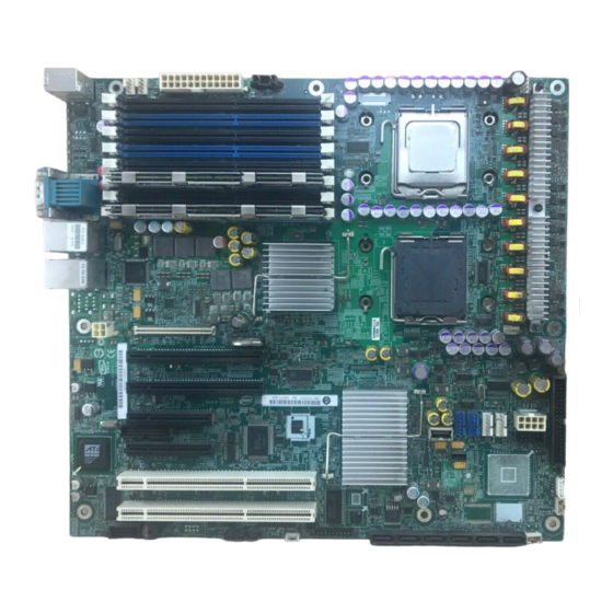
Server Board Features ® This chapter briefly describes the main features of the Intel Server Board S5000PSL. This chapter provides a photograph of the product, a list of the server board features, and diagrams showing the location of important components and connections on the server board. -
Page 20: Table 2. Server Board Features
Xeon processors. Product codes S5000PSLSATAR, S5000PSLSASR, S5000PSLROMBR, and S5000XSLSATAR only • ® ® Up to two 45nm next generation Quad-Core Intel Xeon processors. Product codes S5000PSLSATAR, S5000PSLSASR, S5000PSLROMBR, and S5000XSLSATAR only • System memory support Eight FBDIMM sockets (DDR2-533 and DDR2-667) supporting 32 GB maximum memory •... - Page 21 SATA ports at 1.5 Gbps and 3 Gbps – Product code S5000PSLROMB or S5000PSLROMBR: six ® onboard SATA ports, plus an Intel Integrated Server RAID module in slot 4 adds four internal and four external SAS ® ports. The addition of the Intel RAID Activation Key and a RAID DIMM adds intelligent RAID 0, 1, 5, 10, and 50.
- Page 22 ® Intel Integrated Server RAID provides four internal and ® four external SAS ports. When the optional Intel Activation KEY AXXRAK18E and RAM are installed, hardware RAID support is available for RAID 0, 1, 5, 10, and 50. Uses specially keyed PCI Express slot, add-in card slot 4.
-
Page 23: Connector And Header Locations
PCI Express* x4 or x8 slot 3 Processor 2 socket HH. Hot-swap backplane A header RMM NIC connector Processor 2 fan header SATA 0 PCI Express x4 slot 4 Processor 1 fan header SATA 1 (ROMB slot) ® Intel Server Board S5000PSL... -
Page 24: Figure 2. Server Board Connector And Component Locations
S5000PSLSAS and S5000PSLSASR) RMM connector (connector System fan 1 header OO. USB port ® for Intel Remote Management Module) Back panel I/O ports (see AA. Processor power connector PP. Front control panel header Figure 4 on page Diagnostic and Identify BB. -
Page 25: Configuration Jumpers
To clear the CMOS: Power down the server, leaving AC power connected. Place the jumper on pins 2 - 3 for 5 to 10 seconds. Move the jumper back to pins 1 - 2. Power on the server. ® Intel Server Board S5000PSL... -
Page 26: Figure 3. Configuration Jumpers
BMC Force Update 1 - 2 Disable force update: These pins should be jumpered for normal operation. (J1E3) 2 - 3 Enable force update: Jumpering these pins forces a BMC update. Figure 3. Configuration Jumpers ® Intel Server Board S5000PSL... -
Page 27: Intel ® Light-Guided Diagnostics
® Intel Light-Guided Diagnostics The server board contains diagnostic LEDs to help you identify failed and failing components and to help you identify the server from among several servers. Except for the ID LED, the status LED, and the +5-volt standby LED, the LEDs turn on (amber) only if a failure occurs. - Page 28 This LED indicates a fault has occurred with the FBDIMM installed in socket DIMM_A2. Replace the faulty FBDIMM. DIMM B1 fault LED This LED indicates a fault has occurred with the FBDIMM installed in socket DIMM_B1. Replace the faulty FBDIMM. ® Intel Server Board S5000PSL...
- Page 29 Processor 1 fan fault LED This LED applies only to server systems that use an active heatsink. This LED indicates a fault has occurred with fan that is installed on the heatsink for processor 1. Replace the faulty unit. ® Intel Server Board S5000PSL...
-
Page 30: Back Panel Features
Back Panel Features The diagram and table show the back panel connectors and LEDs. For information about ® the LEDs, see “Intel Light-Guided Diagnostics” on page AF000421 Mouse (top), Keyboard (bottom) Bit 1 LED (POST LED) Status LED LSB LED (POST LED) -
Page 31: Raid Support
I C interface. Notes: ® • For help with navigating the BIOS Setup utility, see the Intel Server Board S5000PSL Technical Product Specification. • For help with enclosure management cabling, see the Enclosure Management Cabling Guide for Pedestal Systems with Hot-swap Drive Backplanes. -
Page 32: Sas Server Board
To enable RAID 5, this activation key is placed on the SAS_Key connector that ® is located at the left side of the server board. For information on how to install the Intel RAID Activation Key AXXRAKSW5 accessory to enable RAID 5, see the documentation that is included with the accessory kit. -
Page 33: Romb Server Board
SES2 (inband). For help with enclosure management cabling, see the Enclosure Management Cabling ® Guide for Pedestal Systems with Hot-swap Drive Bacplanes. This guide is on the Intel Server Deployment Toolkit 2.0 CD. ® Intel... -
Page 34: Hardware Requirements
® ® Intel Xeon processors 5300 sequence. ® ® • One or two 45 nm next generation Quad-Core Intel Xeon processors (Product codes S5000PSLSATAR, S5000PSLSASR, S5000PSLROMBR, and S5000XSLSATAR only) ® ® • One or two 45 nm 2P Dual-Core Intel... -
Page 35: Figure 5. Dimm Sockets
DIMM_C1 Branch 1, Channel A, Branch 2, Channel C, DIMM_A2 DIMM_C2 Branch 1, Channel B, Branch 2, Channel D, DIMM_B1 DIMM_D1 Branch 1, Channel B, Branch 2, Channel D, DIMM_B2 DIMM_D2 Figure 5. DIMM Sockets ® Intel Server Board S5000PSL... -
Page 36: Power Supply
Information and Software” on page viii Power Supply A minimum of 550 watts is required. Your power supply must provide a minimum of 3 amps of 5-volt standby current or the server will not boot. ® Intel Server Board S5000PSL... -
Page 37: Optional Hardware
RAID 5 support on your server board. For the SATA server board, product code ® S5000PSLSATA or S5000PSLSATAR, an Intel RAID Activation Key can be installed in the SATA RAID 5 Key connector. For the SAS server board, product code S5000PSLSAS ®... -
Page 38: Intel Remote Management Module / Intel Remote Management Module 2 And Rmm Nic / Rmm2 Nic
See the documentation included with your server chassis for additional drive information and drive installation instructions. ® ® Intel Remote Management Module / Intel Remote Management Module 2 and RMM NIC / RMM2 NIC ® ® The Intel Remote Management Module / Intel... -
Page 39: Chapter 2: System Utilities
System Utilities Using the BIOS Setup Utility This section describes the BIOS Setup Utility options, which is used to change system configuration defaults. You can run BIOS Setup with or without an operating system being present. See “Additional Information and Software” for a link to the Technical Product Specification where you will find details about specific BIOS setup screens. -
Page 40: Setup Menus
When the <Esc> key is pressed in any submenu, the parent menu is re-entered. When the <Esc> key is pressed in any major menu, the exit confirmation window is displayed and the user is asked whether changes can be discarded. ® Intel Server Board S5000PSL... -
Page 41: Upgrading The Bios
BIOS, the system reverts to the BIOS that was in place before the upgrade was performed. This provides a safeguard against problems that might happen during the upgrade, such as a power outage during the upgrade process. This is called the rolling BIOS feature. ® Intel Server Board S5000PSL... -
Page 42: Preparing For The Upgrade
Note: You may encounter a CMOS Checksum error or other problem after reboot. If this happens, shut down the system and boot it again. CMOS checksum errors require that you enter Setup, check your settings, save your settings, and exit Setup. ® Intel Server Board S5000PSL... -
Page 43: Reverting To The Previous Bios
5. Close the chassis. 6. Reconnect the AC power and power up the server. The BIOS will boot to the previous BIOS until you either move the jumper again or until you perform another BIOS update. ® Intel Server Board S5000PSL... -
Page 44: Clearing The Password
5. Power up the server and wait 10 seconds. 6. Power down the server. 7. Move the Password Clear jumper back to the original position, covering pins 1 and 2. 8. Close the chassis. 9. Power up the server. ® Intel Server Board S5000PSL... -
Page 45: Clearing The Cmos
Figure 8. CMOS Clr Jumper in the Clear CMOS Position 5. Wait 10 seconds. 6. Move the CMOS Clear jumper back to the original position, covering pins 1 and 2. 7. Close the chassis. 8. Power up the server. ® Intel Server Board S5000PSL... - Page 46 ® Intel Server Board S5000PSL...
-
Page 47: Chapter 3: Hardware Installations And Upgrades
Hardware Installations and Upgrades Before You Begin Before working with your server product, pay close attention to the “Safety Information” on page iii. Tools and Supplies Needed • Phillips* (cross head) screwdriver (#1 bit and #2 bit) • Needle nosed pliers •... -
Page 48: Figure 9. Locating Dimm Sockets
6. Disconnect and remove any components necessary to access the DIMM sockets. See the documentation that came with your chassis for instructions on removing chassis components. AF000093 Callout DIMM Socket Callout DIMM Socket DIMM_A1 DIMM_C1 DIMM_A2 DIMM_C2 DIMM_B1 DIMM_D1 DIMM_B2 DIMM_D2 Figure 9. Locating DIMM Sockets ® Intel Server Board S5000PSL... -
Page 49: Figure 10. Installing Fbdimms
See the documentation that came with your chassis for instructions on removing chassis components. 14. Replace the chassis cover and reconnect the AC power cord. See the documentation that came with your chassis for instructions on installing the chassis cover. ® Intel Server Board S5000PSL... -
Page 50: Removing Fbdimms
(1) Touch the metal chassis before touching the processor or server board. Keep part of your body in contact with the metal chassis to dissipate the static charge while handling the processor. (2) Avoid moving around unnecessarily. ® Intel Server Board S5000PSL... -
Page 51: Installing The Processor
3. Disconnect the AC power cord from the server. 4. Remove the chassis cover. See the documentation that came with your chassis for instructions on removing the cover. 5. Locate the processor sockets (see Figure 11). ® Intel Server Board S5000PSL... -
Page 52: Figure 11. Locating Processor Sockets
7. Push down on the lever attached to the processor socket. While holding the lever down, pull it towards the center of the board to disengage the lever from the hook. Fully open the lever. See Figure ® Intel Server Board S5000PSL... -
Page 53: Figure 12. Opening Processor Socket Lever
Figure 12. Opening Processor Socket Lever 8. Push down on the rear tab of the load plate to swing the front of the load plate up slightly. Fully open the load plate. See Figure AF000096 Figure 13. Opening Load Plate ® Intel Server Board S5000PSL... -
Page 54: Figure 14. Removing Protective Cover From Load Plate
13. Close the socket lever. Push downward on the socket lever while pushing it toward the center of the processor socket to engage it under the hook on the processor socket. 14. Install the heatsink(s). See “Installing the Heatsink(s)” on page 37 for instructions. ® Intel Server Board S5000PSL... -
Page 55: Installing The Heatsink(S)
The following table shows the ® Intel server chassis compatible with this server board and whether each chassis requires an active or a passive heatsink: ® Table 5. Heatsink Requirements for Compatible Intel Server Chassis Server Chassis Heatsink Requirement ® Intel... -
Page 56: Figure 16. Installing Heatsink (Passive Heatsink Shown)
16. Do not fully tighten one screw before loosely attaching the others. 4. In the same order, gradually and equally tighten each captive screw until each is firmly tightened. Do not fully tighten one screw at a time. AF000098 Figure 16. Installing Heatsink (passive heatsink shown) ® Intel Server Board S5000PSL... -
Page 57: Figure 17. Locating Active Heatsink Cable Connections
See the documentation that came with your chassis for instructions on installing chassis components. 7. Replace the chassis cover and reconnect the AC power cord. See the documentation that came with your chassis for instructions on installing the cover. ® Intel Server Board S5000PSL... -
Page 58: Removing A Processor
Doing so will cause your server to overheat and may cause permanent damage. — The heatsink has Thermal Interface Material (TIM) located on the bottom of it. Use caution when handling the heatsink so you do not damage the TIM. ® Intel Server Board S5000PSL... -
Page 59: Figure 18. Opening Processor Socket Lever
Figure 18. Opening Processor Socket Lever 11. Push down on the rear tab of the load plate to swing the front of the load plate up slightly. Fully open the load plate. See Figure AF000415 Figure 19. Opening Load Plate ® Intel Server Board S5000PSL... -
Page 60: Figure 20. Removing Processor From Socket
13. Store the processor in the packaging materials in which it came. 14. Install the protective cover over the load plate if a replacement processor will not be installed. AF000417 Figure 21. Installing Protective Cover onto Load Plate ® Intel Server Board S5000PSL... -
Page 61: Replacing The Cmos Battery
Varning: Explosionsfara vid felaktigt batteribyte. Använd samma batterityp eller en ekvivalent typ som rekommenderas av apparattillverkaren. Kassera använt batteri enligt fabrikantens instruktion. Varoitus: Paristo voi räjähtää, jos se on virheellisesti asennettu. Vaihda paristo ainoastaan laitevalmistajan suosittelemaan tyyppiin. Hävitä käytetty paristo valmistajan ohjeiden mukaisesti. ® Intel Server Board S5000PSL... -
Page 62: Figure 22. Locating And Removing The Cmos Battery
11. Replace the chassis cover and reconnect the AC power cord. See the documentation that came with your chassis for instructions on installing the cover. 12. Run the BIOS Setup utility to restore the configuration settings to the real-time clock. ® Intel Server Board S5000PSL... -
Page 63: Appendix A: Troubleshooting
In addition to the system firmware and files, also update any drivers used for components you have installed in your system, such as video drivers and network drivers. Intel provides a package called the “Platform Confidence Test” that may help with your diagnostics. See “Additional Information and Software”... -
Page 64: Problems Following Initial System Installation
Are all integrated components from the tested components lists? Check the tested memory, and chassis lists, as well as the supported hardware and operating system list. See “Additional Information and Software” on page viii for links to the tested component lists. ® Intel Server Board S5000PSL... -
Page 65: Hardware Diagnostic Testing
DVD-ROM Drive Activity Light Does Not Light” on page ® • If system LEDs are illuminated, see “Intel Light-Guided Diagnostics” on page 9 for a description of the lights. Confirming Loading of the Operating System Once the system boots up, the operating system prompt appears on the screen. The prompt varies according to the operating system. -
Page 66: Specific Problems And Corrective Actions
Make sure the chassis standoffs are installed only below mounting holes. Misplaced standoffs can contact the pins on the bottom of the server board and cause a short. • In a DC powered system, make sure all DC cables are connected. ® Intel Server Board S5000PSL... -
Page 67: No Characters Appear On Screen
5. If you do not receive a beep code and characters do not appear, the video display monitor or video controller may have failed. Contact your service representative or authorized dealer for help. ® Intel Server Board S5000PSL... -
Page 68: Characters Are Distorted Or Incorrect
CD-ROM Drive or DVD-ROM Drive Activity Light Does Not Light Check the following: • Are the CD-ROM/DVD-ROM drive's power and signal cables properly installed? • Are all relevant switches and jumpers on the drive set correctly? • Is the drive properly configured? ® Intel Server Board S5000PSL... -
Page 69: Cannot Connect To A Server
Make sure your BIOS is current. See “Additional Information and Software” for a link to the current version. • Make sure the other adapter supports shared interrupts. Make sure your operating system supports shared interrupts. • Try reseating the add-in adapter. ® Intel Server Board S5000PSL... -
Page 70: System Boots When Installing Pci Card
If you are running the software from a USB floppy disk, CD-ROM or DVD-ROM, try a different disk. • Make sure the correct device drivers installed. If the problems persist, contact the software vendor's customer service representative. ® Intel Server Board S5000PSL... -
Page 71: Problems With Application Software That Ran Correctly Earlier
Devices are not Recognized under Device Manager (Windows* Operating System) ® The Windows* operating systems do not include all of the drivers for the Intel chipsets, onboard NICs, and other components. See “Additional Information and Software” on page viii for a link to the current drivers and chipset files. -
Page 72: Bootable Cd-Rom Disk Is Not Detected
Make sure the BIOS is configured to allow the CD-ROM to be the first bootable device. LED Information ® The Intel Server Board S5000PSL includes LEDs that can aid in troubleshooting your ® system. For the location of the LEDs, see “Intel... -
Page 73: Table 8. Error Beep Codes Generated By Intel ® Remote Management Module
® In addition to the beep codes above, additional beep codes are provided if an Intel ® Remote Management Module is installed. The Intel Remote Management Module provides the following additional beep codes. ® Table 8. Error Beep Codes Generated by Intel... - Page 74 ® Intel Server Board S5000PSL...
-
Page 75: Appendix B: Regulatory And Compliance Information
Server Board S5000PSL has been has been tested and verified to comply with the following electromagnetic compatibility (EMC) regulations when installed a ® compatible Intel host system. For information on compatible host system(s) see Intel's Server Builder Web site or contact your local Intel representative. • FCC /ICES-003 - Emissions (USA/Canada) Verification •... -
Page 76: Certifications / Registrations / Declarations
EMC Marking (Class A) Canada CANADA ICES-003 CLASS A CANADA NMB-003 CLASSE A BSMI Marking (Class A) Taiwan Ctick Marking Australia / New Zealand RLL MIC Mark Korea See the regulatory information document for additional information. ® Intel Server Board S5000PSL... -
Page 77: Electromagnetic Compatibility Notices
(1) this device may not cause harmful interference, and (2) this device must accept any interference received, including interference that may cause undesired operation. For questions related to the EMC performance of this product, contact: Intel Corporation 5200 N.E. Elam Young Parkway Hillsboro, OR 97124-6497 1-800-628-8686 This equipment has been tested and found to comply with the limits for a Class A digital device, pursuant to Part 15 of the FCC Rules. -
Page 78: Ices-003 (Canada)
Interference (VCCI) from Information Technology Equipment. If this is used near a radio or television receiver in a domestic environment, it may cause radio interference. Install and use the equipment according to the instruction manual. ® Intel Server Board S5000PSL... -
Page 79: Bsmi (Taiwan)
RRL (Korea) English translation of the notice above: 1. Type of Equipment (Model Name): On License and Product 2. Certification No.: On RRL certificate. Obtain certificate from local Intel representative 3. Name of Certification Recipient: Intel Corporation 4. Date of Manufacturer: Refer to date code on product 5. -
Page 80: Product Ecology Change (Eu Rohs)
Product Ecology Change (EU RoHS) Intel has a system in place to restrict the use of banned substances in accordance with the European Directive 2002/95/EC. Compliance is based on declaration that materials banned in the RoHS Directive are either (1) below all applicable threshold limits or (2) an approved / pending RoHS exemption applies. - Page 81 CRoHS Substance Tables China CRoHS requires products to be provided with controlled substance information. Intel understands the end-seller (entity placing product into market place) is responsible for providing the controlled substance information. Controlled substance information is required to be in Simplified Chinese. Substance table for this board product is as follows: ®...
-
Page 82: China Packaging Recycle Marks (Or Gb18455-2001)
The State of California requires a warning to be included for products containing a device using Lithium Perchlorate. Intel understands CA Lithium Perchlorate require a printed warning to be included with all products containing a Lithium battery, either as an insert, in existing product literature, or as part of the shipping memo wording. -
Page 83: Appendix C: Getting Help
Telephone All calls are billed per incident, levied in local currency at the applicable credit card exchange rate plus applicable taxes. (Intel reserves the right to change the pricing for telephone support at any time without notice). Before calling, fill out an “System Issue Report... -
Page 84: Latin America
Brazil ..001-916 377 0180 Chile Easter Island....Contact AT&T USA at 800 800 311. Once connected, dial 800 843 4481 Mainland and Juan .. Contact AT&T USA at 800 225 288. Once connected, dial 800 843 4481 ® Intel Server Board S5000PSL... - Page 85 Panama..Contact AT&T USA at 00 800 001 0109. Once connected, dial 800 843 4481 Paraguay ... 001 916 377 0114 Peru ... 001 916 377 0114 Uruguay..001 916 377 0114 Venezuela... Contact AT&T USA at 0 800 2255 288. Once connected, dial 800 843 4481 ® Intel Server Board S5000PSL...
- Page 86 ® Intel Server Board S5000PSL...
-
Page 87: Appendix D: System Issue Report Form
Appendix D: System Issue Report Form Note: An on-line / automatic submission version of this form is available at http:// support.intel.com/support/motherboards/server/S5000PSL/. For the fastest service, please submit your form via the Internet. Date Submitted: _______________________________________________________ Company Name: ______________________________________________________ Contact Name: ________________________________________________________... - Page 88 Check each box below as applicable, and provide the requested information. Driver I/O Base Peripheral Description Revision Address Revision Add-in Card Slot 1 Slot 2 Slot 3 Slot 4 Slot 5 Slot 6 Video On-board video Add-in video ® Intel Server Board S5000PSL...
- Page 89 Drive Type (SATA, Hot-swap Make/Model SAS, etc.) or Fixed Revision Management Information No management module installed _________________________________________ ® Intel Remote Management Module _______________________________________ Control Panel Information Standard Control Panel _________________________________________________ ® Intel Local Control Panel_______________________________________________ ® Intel Server Board S5000PSL...
- Page 90 Please also include any details on troubleshooting already done. ____________________________________________________________________ ____________________________________________________________________ ____________________________________________________________________ ____________________________________________________________________ ____________________________________________________________________ ____________________________________________________________________ ____________________________________________________________________ ____________________________________________________________________ ____________________________________________________________________ ____________________________________________________________________ ____________________________________________________________________ ____________________________________________________________________ ____________________________________________________________________ ____________________________________________________________________ ____________________________________________________________________ ____________________________________________________________________ ____________________________________________________________________ ____________________________________________________________________ ____________________________________________________________________ ____________________________________________________________________ ____________________________________________________________________ ® Intel Server Board S5000PSL...
Need help?
Do you have a question about the S5000PSL - Server Board Motherboard and is the answer not in the manual?
Questions and answers