Table of Contents
Advertisement
Quick Links
EP-6WEA4
EP-6WEA4
EP-6WEA4
EP-6WEA4
EP-6WEA4
EP-6WEA4I
EP-6WEA4I
EP-6WEA4I
EP-6WEA4I
EP-6WEA4I
A P entium
A P
A P
entium
entium
entium
A P
A P
entium
Pr
Pr ocessor based
Pr
ocessor based
ocessor based A A A A A GP mainboar
ocessor based
Pr
Pr
ocessor based
(133/100/66MHz)
(133/100/66MHz)
(133/100/66MHz)
(133/100/66MHz)
(133/100/66MHz)
TRADEMARK
All products and company names are trademarks or registered
trademarks of their respective holders.
These specifications are subject to change without notice.
II or P
II or P entium
II or P
entium
entium
entium
II or P
II or P
entium
® ® ® ® ®
Manual Revision 1.0
November 23, 1999
III Slot1
III Slot1
III Slot1
III Slot1
III Slot1
® ® ® ® ®
GP mainboar d d d d d
GP mainboar
GP mainboar
GP mainboar
Advertisement
Table of Contents

Related Manuals for EPOX EP-6WEA4


Summary of Contents for EPOX EP-6WEA4
- Page 1 EP-6WEA4 EP-6WEA4 EP-6WEA4 EP-6WEA4 EP-6WEA4 EP-6WEA4I EP-6WEA4I EP-6WEA4I EP-6WEA4I EP-6WEA4I A P entium entium entium entium II or P II or P II or P entium entium entium entium III Slot1 III Slot1 III Slot1 entium II or P II or P...
-
Page 2: User Notice
EPoX has been advised of the possibility of such damages arising from any defect or error in the manual or product. EPoX may revise this manual from time to time without notice. - Page 3 EP-6WEA4/4I serial number: __________________________ Contacting Technical Support EPoX technical support is working hard to answer all of your questions online. From our website you can find answers to many common questions, drivers, BIOS updates, tech notes, and important technical bulletins. If you are still unable to locate the solution you are seeking, you always have the option to contact our support technicians directly.
-
Page 4: Table Of Contents
Power-On/Off (Remote) .......... 1-7 System Block Diagram ..........1-8 Section 2 Features EP-6WEA4/4I Features ........... 2-1 Section 3 Installation EP-6WEA4/4I Detailed Layout ........ 3-2 Easy Installation Procedure Configure Jumpers ...........3-3 AC’97/MR Configuration Table ....... 3-4 System Memory Configuration ........ 3-5 ® Installing a Pentium II/III Processor .......3-7... - Page 5 EP-6WEA4/4I PNP/PCI Configuration Setup .........4-21 PC Health Status ............4-22 Frequency/Voltage Control ........4-24 Defaults Menu ............4-25 Supervisor/User Password Setting ......4-26 Exit Selecting ............4-27 Section 5 810E VGA and Sound Driver Installation Easy Driver Installation ..........5-1 Appendix Appendix A Memory Map ............A-1 I/O Map ..............A-1...
- Page 6 EP-6WEA4/4I Page Left Blank...
-
Page 7: Introduction
Section 1 INTRODUCTION Components Checklist ü ü ü ü ü EP-6WEA4/4I mainboard ü ü ü ü ü EP-6WEA4/4I user’s manual ü ü ü ü ü Floppy ribbon cable ü ü ü ü ü D. (1) ATA-66 Hard driver ribbon cables ü... -
Page 8: Overview
Introduction EP-6WEA4/4I Overview Pentium II or Pentium III Processor ® ® ® ® ® The Pentium II or Pentium III Processor (The Pentium III Processor as 350~600/ 100MHz and 533~733/133MHz speed or above with 512K/256K-L2 cache ® ® ® Versions.) is the follow-on to the Pentium Processor. -
Page 9: Cartridge Terminology
EP-6WEA4/4I Introduction ® ® The entire enclosed product is called the Pentium II or Pentium III Processor. The packaging technology and each of the physical elements of the product are referred to using accurate technical descriptions. This allows clear reference to the products as just a processor. -
Page 10: Intel ® 810E Chipset Feature
Introduction EP-6WEA4/4I The L2 cache (TagRAM, PBSRAM) components keep standard industry names. ® ® The Pentium II or Pentium III Processor is the first product to utilize the S.E.C. cartridge technology and Slot 1 connector. Unless otherwise noted, any refer- ®... - Page 11 EP-6WEA4/4I Introduction The 82802AB Firmware Hub (FWH, 4MB) stores system BIOS and video BIOS, eliminating a redundant nonvolatile memory component. In addition, the 82802AB contains a hardware Random Number Generator (RNG). The Intel(R) RNG provides truly random numbers to enable fundamental security building blocks supporting stronger encryption, digital signing, and security protocols for the future application program .
-
Page 12: Ep-6Wea4/4I Form-Factor
EP-6WEA4/4I EP-6WEA4/4I Form-Factor The EP-6WEA4/4I is designed with ATX form factor - the new industry standard of chassis. The ATX form factor is essentially a Baby-AT baseboard rotated 90 degrees within the chassis enclosure and a new mounting configuration for the power supply. -
Page 13: I/O Shield Connector
EP-6WEA4/4I Introduction I/O Shield Connector The EP-6WEA4/4I is equipped with an I/O back panel. Please use the appropri- ate I/O shield (figure 3). Joystick/Midi parallel port port PS/2 Mouse USB port PS/2 KEYBOARD COM1 VGA1 Speaker Line_in Figure 3: I/O back panel layout Power-On/Off (Remote) The EP-6WEA4/4I has a single 20-pin connector for ATX power supplies. -
Page 14: System Block Diagram
Introduction EP-6WEA4/4I System Block Diagram Figure 5: System Block Diagram Page 1-8... -
Page 15: Features
Supports (5) 32 bit PCI slots, provides (2) independent high performance PCI IDE interfaces capable of supporting PIO Mode 3/4 and Ultra DMA 66 devices. The EP-6WEA4/4I supports (5) PCI Bus Master slots and a jumperless PCI INT# control scheme which reduces configuration confu- sion when plugging in PCI card(s). - Page 16 Features EP-6WEA4/4I • EP-6WEA4/4I utilizes a Lithium battery which provides environmental protection and longer battery life. • Supports the Universal Serial Bus (USB) connector. The onboard ICH (82801AA) chip provides the means for connecting PC peripherals such as; keyboards, joysticks, speaker, and mouse.
- Page 17 EP-6WEA4/4I Installation Page 3-1...
-
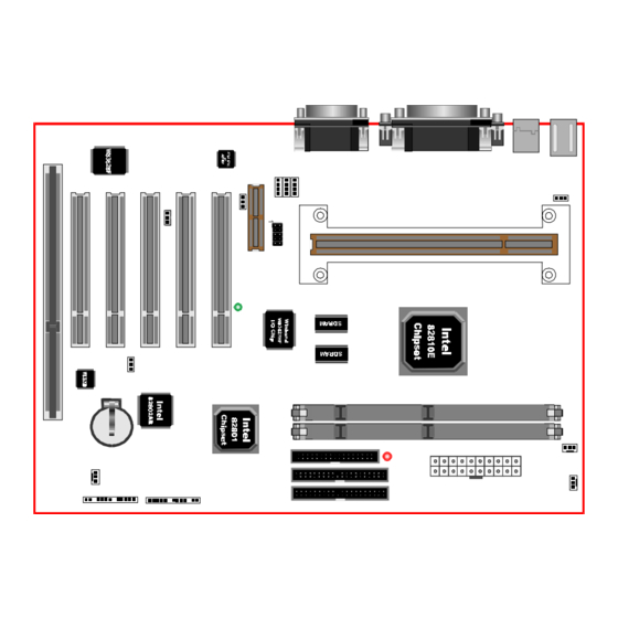
Page 18: Ep-6Wea4/4I Detailed Layout
Installation EP-6WEA4/4I EP-6WEA4/4I Detailed Layout Figure 1 Page 3-2... -
Page 19: Configure Jumpers
EP-6WEA4/4I Installation The following must be completed before powering on your new system: 3-1. Configure Jumpers to match your hardware 3-2. System Memory Configuration ® ® 3-3. Install Pentium II or Pentium III Processor 3-4. Device Connectors 3-5. External Modem Ring-in Power ON and Keyboard Power ON Functions (KBPO) 3-6. - Page 20 Installation EP-6WEA4/4I On Board AC’97 Codec Audio JP8 = 1-2 Enabled (Default for EP-6WEA4/EP-6WEA4I) = 2-3 Disabled AC’97/MR Configuration Table Audio Codec’97 (AC’97) Audio Codec (AC) Modem Codec (MC) **** Audio/Modem Codec (AMC) ***** Modem Riser Card (MR) Note: In the BIOS setting, “AC97 Audio” of “Integrated Peripher- als”...
- Page 21 EP-6WEA4/4I Installation The EP-6WEA4/4I supports (2) 168-pin DIMMs (Dual In-line Memory Module). The DIMMs can be either EDO (Extended Data Out) or SDRAM (Synchronized DRAM). • 100MHz system memory bus frequency. Even if the system host bus is 66MHz. •...
- Page 22 Installation EP-6WEA4/4I Figure 3 displays the notch marks and what they should look like on your DIMM memory module. DIMMs have 168-pins and two notches that will match with the onboard DIMM socket. DIMM modules are installed by placing the chip firmly into the socket at a 90 degree angle and pressing straight down (figure 4) until it fits tightly into the DIMM socket (figure 5).
- Page 23 EP-6WEA4/4I Installation ® The EP-6WEA4/4I uses the Single Edge Contact (SEC) slot for a Pentium II/III processor packaged in an SEC cartridge. The SEC slot is not compatible with ® other non-Pentium II/III processors. Please have ready the following list of components so that we may install the processor onto the motherboard.
- Page 24 Installation EP-6WEA4/4I cable will be shipped with the boxed processor to draw power from a power header on the mainboard’s J4. Now we are ready to install the SEC Cartridge (Pentium II/III Processor) into the Retention Module. The SEC Cartridge is mounted by sliding the SEC Cartridge into the Retention Module and letting it slide all the way down.
- Page 25 EP-6WEA4/4I Installation Please install the motherboard into the chassis. Now that your motherboard is installed you are ready to connect all your connec- tions (figure 7). parallel port Joystick/Midi PS/2 Mouse USB port PS/2 KEYBOARD COM1 VGA1 Speaker Line_in Figure 7 J2,J3: Chassis Panel Connector •...
- Page 26 Installation EP-6WEA4/4I Power On/Off (This is connected to the power button on the case. Using the Soft- Off by Pwr-BTTN feature, you can choose either Instant Off (turns system off immediatly), or 4 sec delay (you need to hold the button down for 4 seconds before the system turns off).
- Page 27 On the basis of bounded functions in I/O chipset, the two serial ports are able to support the External Modem Ring-in Power ON function. Once users connect the external modem to COM1 or COM2, the EP-6WEA4/4I mainboard allows users to turn on their system through the remote and host's dial-up control.
- Page 28 Notes: 1. Intel ATX version 2.0 specification has recommended you use the power supply with 1.0A in 5.0VSB. With our EP-6WEA4/4I mainboard, the 5.0VSB standby power only has to be > = 0.1A (100mA) then you can enjoy this unique benefit. However, the ATX power supply which is < 0.1 (100mA) is still applicable to your system by placed JP13 at the position 2-3 to disable this feature.
- Page 29 EP-6WEA4/4I Installation The EP-6WEA4/4I supports the STR power management state by maintaining the appropriate states on the RDRAM interface signals. The power source must be kept alive to the SDRAM during STR (ACPI S3). Advanced Configu- ration Power Interface (ACPI) provides more Energy Saving Features for operating systems that support OS such as ON and QuickStart function.
- Page 30 Installation EP-6WEA4/4I d. You must push the Power button connected with onboard J3 pin to wake up you system (not to click to mouse or press keyboard to wake up the system.) Just pushing Power button, your system will quickly back to the last screen for you.
-
Page 31: Bios Setup
EP-6WEA4/4I BIOS Section 4 BIOS SETUP Main Menu Once you enter the AwardBIOS™ CMOS Setup Utility, the Main Menu will appear on the screen. The Main Menu allows you to select from several setup functions and two exit choices. Use the arrow keys to select among the items and press <Enter>... - Page 32 BIOS EP-6WEA4/4I Advanced BIOS Features Use this menu to set the Advanced Features available on your system. Advanced Chipset Features Use this menu to change the values in the chipset registers and optimize your system’s performance. Integrated Peripherals Use this menu to specify your settings for integrated peripherals.
-
Page 33: Standard Cmos Setup
EP-6WEA4/4I BIOS 4-1 Standard CMOS Setup The items in Standard CMOS Setup Menu are divided into 10 categories. Each cat- egory includes no, one or more than one setup items. Use the arrow keys to high- light the item and then use the <PgUp> or <PgDn> keys to select the value you want in each item. -
Page 34: Main Menu Selections
BIOS EP-6WEA4/4I Main Menu Selections This table shows the selections that you can make on the Main Menu Item Options Description Date Month YYYY Set the system date. Note that the ‘Day’ automatically hanges when you set the date Time... -
Page 35: Ide Adapters
EP-6WEA4/4I BIOS IDE Adapters The IDE adapters control the hard disk drive. Use a separate sub menu to configure each hard disk drive. Figure 2 shows the IDE primary master sub menu. Figure 2 IDE Primary Master sub menu Page 4-5... - Page 36 BIOS EP-6WEA4/4I Use the legend keys to navigate through this menu and exit to the main menu. Use Table 3 to configure the hard disk. Item Options Description IIDE HDD Auto-detection Press Enter Press Enter to auto-detect the HDD on this channel. If detection is successful, it fills the remaining fields on this menu.
-
Page 37: Advanced Bios Features
EP-6WEA4/4I BIOS 4-2 Advanced BIOS Features This section allows you to configure your system for basic operation. You have the opportunity to select the system’s default speed, boot-up sequence, keyboard operation, shadowing and security. Virus Warning Allows you to choose the VIRUS Warning feature for IDE Hard Disk boot sector protection. - Page 38 BIOS EP-6WEA4/4I CPU L2 Cache ECC Checking This item allows you to enable/disable CPU L2 Cache ECC checking. The choice: Enabled, Disabled. Processor Number Feature Pentium III or later CPU new feature. The default is Enabled. Enabled: Processor serial number readable.
- Page 39 EP-6WEA4/4I BIOS Typematic Rate Setting Key strokes repeat at a rate determined by the keyboard controller. When enabled, the typematic rate and typematic delay can be selected. The choice: Enabled/Disabled. Typematic Rate (Chars/Sec) Sets the number of times a second to repeat a key stroke when you hold the key down.
-
Page 40: Advanced Chipset Features
BIOS EP-6WEA4/4I 4-3 Advanced Chipset Features This section allows you to configure the system based on the specific features of the installed chipset. This chipset manages bus speeds and access to system memory resources, such as DRAM and the external cache. It also coordinates communica- tions between the conventional ISA bus and the PCI bus. - Page 41 EP-6WEA4/4I BIOS SDRAM CAS Latency Time (This field is no function) When synchronous DRAM is installed, the number of clock cycles of CAS latency depends on the DRAM timing. The Choice: 2, 3 RDRAM Device Napdown Select Enabled the RDRAM channel inactivity counter to start counting the continu- ous inactivity time.
- Page 42 BIOS EP-6WEA4/4I On-Chip Video Window Size The amount of system memory that the 810 AGP is allowed to share. The default is 64. 32: 32MB of systems memory accessable by the 810 AGP. 64: 64MB of systems memory accessable by the 810 AGP.
-
Page 43: Integrated Peripherals
EP-6WEA4/4I BIOS 4-4 Integrated Peripherals OnChip Primary/Secondary PCI IDE The integrated peripheral controller contains an IDE interface with support for two IDE channels. Select Enabled to activate each channel separately. The choice: Enabled, Disabled. IDE Primary/Secondary Master/Slave PIO The four IDE PIO (Programmed Input/Output) fields let you set a PIO mode (0-4) for each of the four IDE devices that the onboard IDE interface supports. - Page 44 BIOS EP-6WEA4/4I USB Controller Select Enabled if your system contains a Universal Serial Bus (USB) controller and you have USB peripherals. The choice: Enabled, Disabled. USB Keyboard Support Select Enabled if your system contains a Universal Serial Bus (USB) controller and you have a USB keyboard.
- Page 45 EP-6WEA4/4I BIOS Password: User can Power On the System by password, the password can be entered from 1 to 5 characters. The maximum of password is 5 characters. If user forget / lost the password, please turn off the system and open case to clear CMOS by JP1 to re-setting the power on function.
- Page 46 BIOS EP-6WEA4/4I Onboard Parallel port This field allows the user to configure the LPT port. The default is 378H / IRQ7. 378H: Enable Onboard LPT port and address is 378H and IRQ7. 278H: Enable Onboard LPT port and address is 278H and IRQ5.
- Page 47 EP-6WEA4/4I BIOS Mida Port Address Select an address for the Mida port. The choice: 290, 300, 330, Disabled. Midi Port IRQ Select an interrupt for the Mida port. The choice: 5, 10. Page 4-17...
-
Page 48: Power Management Setup
BIOS EP-6WEA4/4I 4-5 Power Management Setup The Power Management Setup allows you to configure you system to most effec- tively save energy while operating in a manner consistent with your own style of computer use. ACPI Function This item allows you to enable/disable the Advanced Configuration and Power Man- agement (ACPI). - Page 49 EP-6WEA4/4I BIOS There are four selections for Power Management, three of which have fixed mode settings. Disable (default) No power management. Disables all four modes Min. Power Saving Minimum power management. Doze Mode = 1 hr. Standby Mode = 1 hr., Suspend Mode = 1 hr., and HDD Power Down = 15 min.
- Page 50 BIOS EP-6WEA4/4I HDD Power Down When enabled and after the set time of system inactivity, the hard disk drive will be powered down while all other devices remain active. The choice: Enabled, Disabled. Soft-Off by PWR-BTTN Pressing the power button for more than 4 seconds forces the system to enter the Soft-Off state when the system has “hung.”...
-
Page 51: Pnp/Pci Configuration Setup
EP-6WEA4/4I BIOS 4-6 PnP/PCI Configuration Setup This section describes configuring the PCI bus system. PCI, or Personal Computer Interconnect, is a system which allows I/O devices to operate at speeds nearing the speed the CPU itself uses when communicating with its own special components. -
Page 52: Pc Health Status
BIOS EP-6WEA4/4I Windows95. If you set this field to “manual” choose specific resources by going into each of the sub menu that follows this field (a sub menu is preceded by a “Ø”). The choice: Auto(ESCD), Manual. PCI/VGA Palette Snoop Leave this field at Disabled. - Page 53 EP-6WEA4/4I BIOS Current CPU Temperature This is the current temperature of the CPU. Current System Temperature This is the Current temperature of the system. Current CHASSISFAN / CPUFAN / PWRFAN Speed The current CPU fan speed in RPMs. CPU(V) The voltage level of the Vtt, Vcore, Vcc.
-
Page 54: Frequency/Voltage Control
BIOS EP-6WEA4/4I 4-8 Frequency/Voltage Control 2.00V 0.00V 2.00V Auto Detect DIMM/PCI Clk This item allows you to enable/disable auto detect DIMM/PCI Clock. The choice: Enabled, Disabled. Spread Spectrum This item allows you to enable/disable the spread spectrum modulate. The choice: Enabled, Disabled. -
Page 55: Defaults Menu
EP-6WEA4/4I BIOS 4-9 Defaults Menu Selecting “Defaults” from the main menu shows you two options which are described below Load Fail-Safe Defaults When you press <Enter> on this item you get a confirmation dialog box with a message similar to: Load Fail-Safe Defaults (Y/N) ? N Pressing ‘Y’... -
Page 56: Supervisor/User Password Setting
BIOS EP-6WEA4/4I 4-10 Supervisor/User Password Setting You can set either supervisor or user password, or both of then. The differences between are: supervisor password : can enter and change the options of the setup menus. user password : just can only enter but do not have the right to change the options of the setup menus. -
Page 57: Exit Selecting
EP-6WEA4/4I BIOS 4-11 Exit Selecting Save & Exit Setup Pressing <Enter> on this item asks for confirmation: Save to CMOS and EXIT (Y/N)? Y Pressing “Y” stores the selections made in the menus in CMOS – a special section of memory that stays on after you turn your system off. The next time you boot your computer, the BIOS configures your system according to the Setup selections stored in CMOS. - Page 58 BIOS EP-6WEA4/4I Page Left Blank Page 4-28...
-
Page 59: Drivers Installation
EP-6WEA4/4I Drivers Installation Section 5 810 VGA and Sound Driver Installation Easy Driver Installation Step 1 : To Click the Intel 810 and 820 Chipset INF Files that enable the Intel(R) 810 Chipsets to be recognized by listed operating systems. This installer will unpack updated .INF files into a specified folder. - Page 60 Drivers Installation EP-6WEA4/4I Page Left Blank Page 5-2...
-
Page 61: Appendix
Appendix EP-6WEA4/4I Appendix A A-1 MEMORY MAP Address Range Size Description [00000-7FFFF] 512K Conventional memory [80000-9FBFF] 127K Extended Conventional memory [9FC00-9FFFF] Extended BIOS data area if PS/2 mouse is installed [A0000-C7FFF] 160K Available for Hi DOS memory [C8000-DFFFF] Available for Hi DOS memory and adapter... -
Page 62: Timer & Dma Channels Map
Appendix EP-6WEA4/4I [2F8-2FF] SERIAL port 2. [360-36F] NETWORK ports. [378-37F] PARALLEL port 1. [3B0-3BF] MONOCHROME & PARALLEL port adapter. [3C0-3CF] EGA adapter. [3D0-3DF] CGA adapter. [3F0-3F7] FLOPPY DISK controller. [3F8-3FF] SERIAL port 1. A-3 TIMER & DMA CHANNELS MAP TIMER MAP: TIMER Channel 0 System timer interrupt. -
Page 63: Rtc & Cmos Ram Map
Appendix EP-6WEA4/4I FLOPPY DISK (SMC CHIP). PARALLEL port 1. RTC clock. Available. Available. Available. PS/2 Mouse. MATH coprocessor. Onboard HARD DISK (IDE1) channel. Onboard HARD DISK (IDE1) channel. A-5 RTC & CMOS RAM MAP RTC & CMOS: Seconds. Second alarm. - Page 64 Appendix EP-6WEA4/4I Base memory high byte. Extension memory low byte. Extension memory high byte. 19-2d 2E-2F Reserved for extension memory low byte. Reserved for extension memory high byte. DATE CENTURY byte. INFORMATION FLAG. 34-3F Reserve. 40-7F Reserved for CHIPSET SETTING DATA.
-
Page 65: Post Codes
Appendix EP-6WEA4/4I Appendix B B-1 POST CODES For BIOS 6.0 Code POST (hex) DESCRIPTION Test CMOS R/W functionality. Early chipset initialization: - Disable shadow RAM - Disable L2 cache (socket 7 or below) - Program basic chipset registers Detect memory - Auto-detection of DRAM size, type and ECC. - Page 66 Appendix EP-6WEA4/4I 3. Reset keyboard for Winbond 977 series Super I/O chips. Reserved Reserved Test F000h segment shadow to see whether it is R/W- able or not. If test fails, keep beeping the speaker. Reserved Auto detect flash type to load appropriate flash R/W codes into the run time area in F000 for ESCD &...
- Page 67 Appendix EP-6WEA4/4I checksum fails, use default value instead. 3. Prepare BIOS resource map for PCI & PnP use. If ESCD is valid, take into consideration of the ESCD’s legacy information. 4. Onboard clock generator initialization. Disable respective clock resource to empty PCI & DIMM slots.
- Page 68 Appendix EP-6WEA4/4I Reserved Reserved Reserved Reserved Reserved Reserved Reserved Reserved Test 8254 Reserved Test 8259 interrupt mask bits for channel 1. Reserved Test 8259 interrupt mask bits for channel 2. Reserved Reserved Test 8259 functionality. Reserved Reserved Reserved Initialize EISA slot Reserved 1.
- Page 69 Appendix EP-6WEA4/4I Reserved Test all memory (clear all extended memory to 0) Reserved Reserved Display number of processors (multi-processor platform) Reserved 1. Display PnP logo 2. Early ISA PnP initialization - Assign CSN to every ISA PnP device. Reserved Initialize the combined Trend Anti-Virus code.
- Page 70 Appendix EP-6WEA4/4I 1. Assign resources to all ISA PnP devices. 2. Auto assign ports to onboard COM ports if the corresponding item in Setup is set to “AUTO”. Reserved 1. Initialize floppy controller 2. Set up floppy related fields in 40:hardware.
- Page 71 Appendix EP-6WEA4/4I Initialize ISA PnP boot devices 1. USB final Initialization 2. NET PC: Build SYSID structure 3. Switch screen back to text mode 4. Set up ACPI table at top of memory. 5. Invoke ISA adapter ROMs 6. Assign IRQs to PCI devices 7.
- Page 72 Appendix EP-6WEA4/4I Page Left Blank A-12...
-
Page 73: Load Optimized Defaults
Appendix EP-6WEA4/4I Appendix C NOTE: The "LOAD Optimized DEFAULTS" function loads the system default data directly from ROM and initializes the associated hardware properly. This function will be necessary when you accept this mainboard, or the system CMOS data is corrupted. - Page 74 Appendix EP-6WEA4/4I Page Left Blank A-14...
- Page 75 EP-6WEA4/4I Appendix Appendix D D-1 GHOST 5.1 Quick User’s Guide Installation is very easy. You only need to copy the Ghost5 folder or Ghost.exe to your hard disk. The current market version is for single Client, so the LPT and NetBios portions will not be explained further.
- Page 76 Appendix EP-6WEA4/4I There are 3 hard disk functions: 1. Disk To Disk (disk cloning) 2. Disk To Image (disk backup) 3. Disk From Image (restore backup) Important! 1. To use this function, the system must have at least 2 disks. Press the Tab key to move the cursor.
- Page 77 EP-6WEA4/4I Appendix 4. Click OK to display the following confirmation screen. Select Yes to start. Disk To Image (Disk Backup) 1. Select the location of the Source drive. 2. Select the location for storing the backup file. A-17...
- Page 78 Appendix EP-6WEA4/4I 3. Click OK to display the following confirmation screen. Select Yes to start. Disk From Image (Restore Backup) 1. Select the Restore file. 2. Select the Destination drive of the disk to be restored. A-18...
- Page 79 EP-6WEA4/4I Appendix 3. When restoring disk backup, set the required partition size as shown in the following figure. 4. Click OK to display the following confirmation screen. Select Yes to start. Partition A-19...
- Page 80 Appendix EP-6WEA4/4I There are 3 partition functions: 1. Partition To Partition (partition cloning) 2. Partition To Image (partition backup) 3. Partition From Image (restore partition) Partition To Partition (Partition Cloning) The basic unit for partition cloning is a partition. Refer to disk cloning for the operation method.
- Page 81 EP-6WEA4/4I Appendix 3. Select the path and file name for storing the backup file. 4. Is the file compressed? There are 3 options: (1) No: do not compress data during backup (2) Fast: Small volume compression (3) High: high ratio compression. File can be compressed to its minimum, but this requires longer execution time.
- Page 82 Appendix EP-6WEA4/4I Partition From Image (Restore Partition) Select the backup file to be restored. 2. Select the source partition. 3. Select the disk to be restored. A-22...
- Page 83 EP-6WEA4/4I Appendix 4. Select the partition to be restored. 5. Select Yes to start restoring. Check This function checks the hard disk or backup file for backup or restoration error due to FAT or track error. A-23...
Need help?
Do you have a question about the EP-6WEA4 and is the answer not in the manual?
Questions and answers