HP Xw4400 - Workstation - 2 GB RAM Reference Manual
Hp xw4400 workstation - service and technical reference guide
Hide thumbs
Also See for Xw4400 - Workstation - 2 GB RAM:
- Service and technical reference manual (210 pages) ,
- Quickspecs (93 pages) ,
- Hardware manual (23 pages)
Table of Contents
Advertisement
Quick Links
Advertisement
Table of Contents
Troubleshooting

Subscribe to Our Youtube Channel
Related Manuals for HP Xw4400 - Workstation - 2 GB RAM


Summary of Contents for HP Xw4400 - Workstation - 2 GB RAM
- Page 1 HP xw4400 Workstation Service and Technical Reference Guide...
- Page 2 Copyright Information Warranty Trademark Credits © 2008 Copyright Hewlett-Packard Hewlett-Packard Company shall not be liable The HP Invent logo is a trademark of Hewlett- Development Company, L.P. for technical or editorial errors or omissions Packard Company in the U.S. and other contained herein or for incidental or countries.
-
Page 3: Table Of Contents
Table of contents 1 Product overview Product features ........................... 2 Component view ........................2 Front panel components ..................... 3 Rear panel components ...................... 4 Serial number and COA label location ................. 5 Product specifications ......................... 5 Power supply ........................5 Standard power supply .................. - Page 4 Installing the Linux operating system ..............19 HP software ............................20 Restoring the Microsoft Windows Vista operating system ..............20 The HP Backup and Restore (HPBR) process ..............20 Creating system recovery DVDs or CDs ............20 Restoring from HPBR DVDs or CDs ..............20 Restoring directly from the recovery partition ............
- Page 5 Building blocks and partners ................40 Asset tracking and security ....................40 Password security .................... 41 Establishing a setup password using the Computer Setup (F10) Utility ....................41 Establishing a power-on password using workstation setup .... 41 Entering a power-on password ............42 Entering a Setup Password ..............
- Page 6 Cables and connectors ..................56 Hard drives ......................56 Lithium coin cell battery ..................56 Customer Self-Repair ......................... 56 Predisassembly procedures ....................... 57 System board components ......................... 57 System board architecture ....................58 Steps for removal and replacement of components ................58 Disassembly order ......................
- Page 7 Product recycling ..........................99 5 System diagnostics and troubleshooting E-Support ............................101 Help & Support Center and E-Support ................101 Troubleshooting checklist ......................... 102 LED color definitions ........................102 HP Insight Diagnostics Offline Edition ....................102 Key features and benefits ....................103 Theory of operation ......................
- Page 8 SAS RAID 1 configuration ........................ 134 SAS RAID 1E configuration ......................135 Appendix B Appendix B — SATA devices Attaching SATA hard drives ......................137 Configuring system BIOS ........................ 137 Creating RAID volumes ........................138 Deleting RAID volumes ........................138 Appendix C Appendix C —...
- Page 9 No operating system loading ......................169 No operating system loading from hard drive ................... 170 No operating system loading from hard drive, part 1 ............171 No operating system loading from hard drive, part 2 ............171 No operating system loading from hard drive, part 3 ............172 No operating system loading from diskette drive ................
- Page 10 ENWW...
-
Page 11: Product Overview
Product overview This chapter presents an overview of the hardware components of the HP xw4400 Workstation. ● Product features on page 2 ● Product specifications on page 5 ● ENERGY STAR on page 14 ● Dual-core CPUs on page 15 ●... -
Page 12: Product Features
Product features Component view The following image shows a typical HP xw4400 workstation. Drive configurations can vary. For complete and current information on supported accessories and components, see http://partsurfer.hp.com. Figure 1-1 Component view Table 1-1 Component view Item Description Item Description Power supply Processor... -
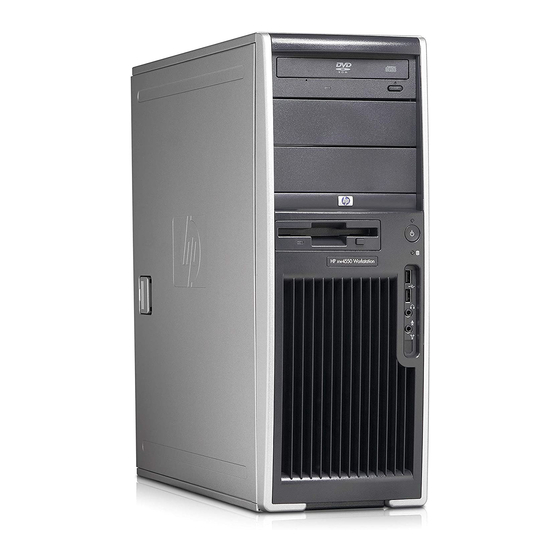
Page 13: Front Panel Components
Front panel components The following image shows a typical HP xw4400 Workstation. Drive configurations can vary. Figure 1-2 Front panel components Table 1-2 Front panel components Item Symbol Description Item Symbol Description Optical drive eject button IEEE-1394 Connector (optional) Power on light Diskette drive eject button Power button Diskette drive activity light... -
Page 14: Rear Panel Components
Rear panel components The following illustrations shows a typical HP xw4400 workstation. Figure 1-3 Rear panel components Table 1-3 Rear panel components Item Symbol Description Item Symbol Description Power supply Built-In Self Test (BIST) LED Graphics adapter Universal chassis clamp opening USB 2.0 (x2) PS/2 mouse connector (green) Microphone connector (pink) -
Page 15: Serial Number And Coa Label Location
Serial number and COA label location Each workstation has two unique serial number labels (1) and a Certificate of Authentication (COA) label (2) (for Windows preinstalled systems only). In general, the serial number labels can be found on the top panel or on the side of the unit and at the rear of the unit. Keep this number available when contacting customer service for assistance. -
Page 16: Power Supply Specifications
Source voltage Description +3.3 V PCI, PCI Express, audio, CK-410, ICH7R, super I/O, BIOS ROM, and on-board logic +5 V Storage (disk, optical, diskette), PCI, PCI Express, ICH7R, audio, keyboard/ mouse +12 V-A PCI, PCI Express, and system fans +12 V-B Storage (disk, optical, diskette), PCI Express x16 auxiliary connector +12 VCPU Input to on-board regulator that supplies power for the CPU... -
Page 17: Power Consumption And Cooling
Table 1-6 Power supply specifications (continued) Item Description (Configuration and software dependent) Maximum 2415 BTU/hr. = (609 kg-cal/hr.) Power Supply fan 92x25 mm variable speed Energy Star compliant Blue Angel Compliant (<5 W in S5 – Power Off) FEMP Standby Power Compliant @115 V (<2 W in S5 –... - Page 18 Table 1-8 Example 1 heat dissipation** 115 VAC 230 VAC 100 VAC Enabled Disabled Enabled Disabled Enabled Disabled Windows Idle (S0) 451 BTU/hr. 437 BTU/hr. 451 BTU/hr. Windows Busy Typ (S0) 662 BTU/hr. 645 BTU/hr. 666 BTU/hr. Windows Busy Max (S0) 884 BTU/hr.
-
Page 19: System Fans
Table 1-10 Example 2 heat dissipation** 115 VAC 230 VAC 100 VAC Enabled Disabled Enabled Disabled Enabled Disabled Windows Idle (S0) 468 BTU/hr. 457 BTU/hr. 481 BTU/hr. Windows Busy Typ (S0) 669 BTU/hr. 652 BTU/hr. 676 BTU/hr. Windows Busy Max (S0) 877 BTU/hr. -
Page 20: Power Supply Specifications
Table 1-11 Power supply source voltages (continued) Source voltage Description +12 V-D Storage (disk, optical, diskette), PCI Express x16 auxiliary connector +12 VCPU Input to on-board regulator that supplies power for the CPU -12 V 5 VSB Sleep circuitry Table 1-12 Max current per rail Voltage rail Maximum continuous current... -
Page 21: Power Consumption And Cooling
Table 1-13 Power supply specifications (continued) Item Description FEMP Standby Power Compliant @115 V (<2 W in S5 - Power Off) Power Consumption in ES Mode – Suspend to < 7 W RAM (S3) (Instantly Available PC) Power consumption and cooling The following table lists the power consumption for one typical configuration based on primary power consumptions. - Page 22 Table 1-15 Example 1 heat dissipation** (continued) 115 VAC 230 VAC 100 VAC Enabled Disabled Enabled Disabled Enabled Disabled Power Off (S5) 6.0 BTU/hr. 3.52 BTU/hr. 7.17 BTU/hr. 4.61 BTU/hr. 6.04 BTU/hr. 3.45 BTU/hr. * Energy Star low energy mode. ** Heat dissipation is calculated based on the measured watts, assuming the service level is attained for one hour.
-
Page 23: System Fans
Table 1-17 Example 2 heat dissipation** (continued) Windows Busy Typ (S0) 574 BTU/hr. 564 BTU/hr. 578 BTU/hr. Windows Busy Max (S0) 621 BTU/hr. 611 BTU/hr. 625 BTU/hr. Sleep (S3)* 12.18 BTU/ 9.59 BTU/hr. 13.21 BTU/ 10.58 BTU/ 12.18 BTU/ 9.35 BTU/hr. Power off (S5) 6.11 BTU/hr. -
Page 24: Energy Star
Non-operating: ● ½-sine: 160 cm/s, 2-3ms (~100g) ● square: 422 cm/s, 20g NOTE: Values represent individual shock events and do not indicate repetitive shock events. Operating random: 0.5g (rms), 5-300 Hz Vibration Non-operating random: 2.0g (rms), 10-500 Hz NOTE: Values do not indicate continuous vibration. ENERGY STAR The ENERGY STAR®... -
Page 25: Dual-Core Cpus
Dual-core CPUs The HP xw4400 Workstation contains a dual-core processor. Like HT Technology, dual-core processors enable better performance over traditional processors. Dual-core processors provide the system with two true processors in a single socket, rather than the two "virtual" processors provided by HT Technology. - Page 26 Chapter 1 Product overview ENWW...
-
Page 27: Installing Or Restoring The Operating System
Installing or restoring the operating system This chapter describes the installation and restoration of the operating system. ● Installing the operating system and software on page 17 ● HP software on page 20 ● Restoring the Microsoft Windows XP operating system on page 21 ●... -
Page 28: Installing Or Upgrading Device Drivers
Installing or upgrading device drivers To install hardware devices after the operating system installation is completed, the appropriate device drivers must be available. In addition, for optimum performance, your operating system must have the most recent updates, patches, and software fixes. Access the following resources for driver and software updates: ●... -
Page 29: Installing The Operating System With The Hp Driver Cd Contents
Installing the operating system with the HP driver CD contents Boot your workstation from the Red Hat box set Binary CD 1. Insert the Linux operating system CDs from the Red Hat box set as prompted. Continue following the prompts until the operating system is successfully installed. Configure the X server to start on reboot. -
Page 30: Hp Software
HP software The following HP software may be installed on your workstation depending on the operating system and options: ● Computer Setup (F10) Utilities and diagnostic features ● HP Support Software including device drivers ● Security Management tools (optional) ● Software Support Management tools Additional software is available for download: ●... -
Page 31: Restoring Directly From The Recovery Partition
Restoring directly from the recovery partition Follow these steps to start the HPBR system restore process from the Recovery Manager: Boot the workstation. Press the F11 key when prompted on the boot splash screen to enter the Recovery Manager. Follow the prompts to restore the system to a factory-like condition. Reclaiming hard disk space from the recovery partition The recovery partition can be removed to reclaim the hard drive space. -
Page 32: Creating A Restoreplus! Cd
this case you must install the application software from the appropriate application CD. The RestorePlus! process can be executed from CD or from the recovery partition contained on your system hard drive. CAUTION: Backup your data before you attempt any operating system restore. All data on the Windows partition will be deleted when you restore using the RestorePlus! process. -
Page 33: Restoring From The Hp Backup And Recovery Manager Restore Point Cd Or Dvds
Restoring from the HP Backup and Recovery Manager restore point CD or DVDs The HP Backup and Recovery Manager (HPBR) restore point can be burned to CD or DVDs and used to restore the system. Typically you would used the CD/DVD set if the hard drive has been replaced or all partitions have been corrupted. - Page 34 Chapter 2 Installing or restoring the operating system ENWW...
-
Page 35: System Management
System management This section describes the various tools and utilities that allow for the system management of the workstation. ● Computer Setup (F10) Utility on page 25 ● Desktop management on page 33 Computer Setup (F10) Utility The Computer Setup (F10) Utility enables you to: ●... -
Page 36: Bios Rom
● Enable power-on password prompting during system restarts (warm boots) and power-on. ● Hide or make available the integrated I/O functionality, including the serial, USB, or parallel ports, audio, or embedded NIC. Any hidden devices are inaccessible and increase overall system security. -
Page 37: Computer Setup (F10) Utility Menu
Use the arrow (left and right) keys to select the appropriate heading. Use the arrow (up and down) keys to select the option you want, and press Enter. To apply and save changes, select File>Save Changes then select Exit. ● If you have made changes that you do not want applied, select Ignore Changes and Exit. - Page 38 Table 3-1 Computer Setup (F10) Utility menu descriptions (continued) Heading Option Description Restores system configuration from a diskette. Default Setup Save Current Settings as Default Saves the current settings as default settings for the next operation. Restore Factory Settings as Default Restores the factory settings as the default settings for the next operation.
- Page 39 Table 3-1 Computer Setup (F10) Utility menu descriptions (continued) Heading Option Description Legacy Diskette Write Enables/disables ability to write data to removable media. BIOS DMA Transfers Enable/disables the BIOS use of DMA for transfers. SATA Emulation Sets the SATA emulation mode with the following options: ●...
- Page 40 Table 3-1 Computer Setup (F10) Utility menu descriptions (continued) Heading Option Description Controller Order Allows you to specify the order of the attached hard drive controller. The first hard drive controller in the order will have priority in the boot sequence and will be recognized as drive C (if any devices are attached).
- Page 41 Table 3-1 Computer Setup (F10) Utility menu descriptions (continued) Heading Option Description Universal Unique Identifier (UUID) Can only be updated if the current chassis serial number is invalid. (These ID numbers are normally set in the factory and are used to uniquely identify the system.) Keyboard Enables you to set the keyboard locale for System ID entry.
- Page 42 Table 3-1 Computer Setup (F10) Utility menu descriptions (continued) Heading Option Description ● Remote Wakeup Boot Source ● After Power Loss (on/off) ● POST Delay (in seconds) (Enable/Disable). Enabling this feature adds a user-specified delay to the POST process. This delay is sometimes needed for hard disks on some PCI cards that spin up slowly—so slowly that they are not ready to boot by the time POST is finished.
-
Page 43: Desktop Management
Table 3-1 Computer Setup (F10) Utility menu descriptions (continued) Heading Option Description SATA RAID Option ROM Download (Enable/Disable) Slot 1 (PCI Configures the option ROM. Express x 16) Slot 2 (PCI) Configures the option ROM and latency timer. Slot 3 (PCI Configures the option ROM. -
Page 44: Remote System Installation
The Restore Plus! CD, ROM-based setup, and ACPI hardware provide further assistance with recovery of system software, configuration management and troubleshooting, and power management. Remote system installation Remote system installation enables you to start and set up your system using the software and configuration information located on a network server. -
Page 45: Altiris Client Management Solutions
Altiris Client Management Solutions HP and Altiris have partnered to provide comprehensive, tightly integrated systems management solutions to reduce the cost of owning HP client PCs. HP Client Manager Software is the foundation for additional Altiris Client Management Solutions that address: ●... -
Page 46: Proactive Change Notification
Proactive Change Notification The Proactive Change Notification program uses the Subscriber's Choice website to proactively and automatically: ● Send you Proactive Change Notification (PCN) emails informing you of hardware and software changes to most commercial workstations and servers, up to 60 days in advance ●... -
Page 47: Failsafe Boot Block Rom
FailSafe Boot Block ROM The FailSafe Boot Block ROM allows for system recovery in the unlikely event of a ROM flash failure, for example, if a power failure were to occur during a ROM upgrade. The Boot Block is a flash-protected section of the ROM that checks for a valid system ROM flash when power to the system is connected. -
Page 48: Replicating The Setup
Replicating the setup The following procedures enable you to easily copy one setup configuration to other workstations of the same model for faster, more consistent configuration of multiple workstations. NOTE: Both procedures require a diskette drive or a USB device such as an HP Drive Key. To collect and replicate BIOS settings on multiple computers, use System Software Manager or HP Client Manager Software. -
Page 49: Dual-State Power Button
As soon as the workstation powers on, press and hold the key until you enter the Computer Setup (F10) Utility. Press Enter to bypass the title screen, if necessary. NOTE: If you do not press the key at the appropriate time, you must restart the workstation and press and hold the key again to access the utility. -
Page 50: Building Blocks And Partners
HP has made the task of locating, accessing, evaluating, and installing the latest support software easier. You can download the software from http://www.hp.com/support. This website contains the latest device drivers, utilities, and flashable ROM images needed to run the latest Microsoft Windows operating system on the HP workstation. -
Page 51: Password Security
Table 3-3 Security Features Overview (continued) Feature Purpose How it is established Serial, Parallel, USB, or Infrared Prevents transfer of data through the From the Computer Setup (F10) Interface Control integrated serial, parallel, USB, or infrared Utility menu. interface. Power-On Password Prevents use of the workstation until the From the Computer Setup (F10) password is entered. -
Page 52: Entering A Power-On Password
When Network Server Mode is disabled, the password must be entered each time the workstation is powered on when the key icon appears on the monitor. When Password Prompt on Warm Boot is enabled, the password must also be entered each time the workstation is rebooted. When Network Server Mode is enabled, the password prompt is not presented during POST, but any attached PS2 keyboard remains locked until you enter the power-on password. -
Page 53: Changing A Power-On Or Setup Password
Changing a power-on or setup password Restart the workstation. To change the Setup password, as soon as the workstation is turned on, press and hold the key until you enter the Computer Setup (F10) Utility. Press Enter to bypass the title screen, if necessary. -
Page 54: Clearing Passwords
Table 3-4 National keyboard delimiter characters Language Delimiter Language Delimiter Language Delimiter Arabic Greek Russian Belgian Hebrew Slovakian BHCSY* Hungarian Spanish Brazilian Italian Swedish/Finnish Chinese Japanese Swiss Czech Korean Taiwanese Danish Latin American Thai French Norwegian Turkish French é Polish U.K. - Page 55 HP recommends that corporate system administrators who choose to enable DriveLock also establish a corporate policy for setting and maintaining master passwords. This should be done to prevent a situation where an employee intentionally or unintentionally sets both DriveLock passwords before leaving the company.
-
Page 56: Hood Sensor (Smart Cover Sensor)
Enter the password again in the Enter New Password Again field. If you forget this password, the drive will be rendered permanently disabled. Select File > Save Changes and Exit and press the F10 key. After you press the F10 key, the system does a “cold boot”... -
Page 57: Hood Lock (Smart Cover Lock)
Select Security>Smart Cover>Cover Removal Sensor, and follow the on-screen instructions. Before exiting, click File>Save Changes and Exit. Hood lock (smart cover lock) When installed, the hood lock can prevent unauthorized access to the internal components. CAUTION: For maximum cover lock security, be sure to establish a setup password. The setup password prevents unauthorized access to the Computer Setup utility. -
Page 58: Clearing Passwords
To obtain the FailSafe Key, complete any one of the following tasks: ● Contact your authorized HP reseller or service provider. ● Access the HP website (http://www.hp.com) for ordering information. ● Access the Contact HP Worldwide website (http://welcome.hp.com/country/us/en/ wwcontact.html) for contact information. Clearing Passwords If you forget your password, you cannot access the workstation. -
Page 59: Drive Protection System
Drive Protection System The Drive Protection System (DPS) is a diagnostic tool built into the hard drives that is installed in select HP workstations. the DPS is designed to help diagnose problems that might result in unwarranted hard drive replacement. When HP workstations are built, each installed hard drive is tested using the DPS, and a permanent record of key information is written onto the drive. - Page 60 Chapter 3 System management ENWW...
-
Page 61: Removal And Replacement Procedures
Removal and replacement procedures This chapter describes removal and replacement procedures of most internal components. ● Warnings and cautions on page 51 ● Service considerations on page 52 ● Customer Self-Repair on page 56 ● Predisassembly procedures on page 57 ●... -
Page 62: Service Considerations
CAUTION: Observe the following cautions when removing or replacing a processor: — Installing a processor incorrectly can damage the system board. Have an HP authorized reseller or service provider install the processor. If you plan to install it yourself, read all of the instructions carefully before you begin. -
Page 63: Preventing Electrostatic Damage To Equipment
Table 4-1 Static electricity Relative humidity Event Walking across carpet 7,500 V 15,000 V 35,000 V Walking across vinyl floor 3,000 V 5,000 V 12,000 V Motions of bench worker 400 V 800 V 6,000 V Removing bubble pack from PCB 7,000 V 20,000 V 26,500 V... -
Page 64: Grounding The Work Area
Grounding the work area To prevent static damage at the work area: ● Cover the work surface with approved static-dissipative material. Provide a wrist strap connected to the work surface and properly grounded tools and equipment. ● Use static-dissipative mats, foot straps, or air ionizers to give added protection. ●... -
Page 65: Screws
Screws The screws used in the workstation are not interchangeable. They might have standard or metric threads and might be of different lengths. If an incorrect screw is used during the reassembly process, it can damage the unit. HP strongly recommends that all screws removed during disassembly be kept with the removed part, and then returned to their proper locations. -
Page 66: Cables And Connectors
Cables and connectors Cables must be handled with care to avoid damage. Apply only the tension required to seat or unseat the cables during insertion or removal from the connector. Handle cables by the connector or pull strap whenever possible. In all cases, avoid bending or twisting the cables, and be sure that the cables are routed in such a way that they cannot be caught or snagged by parts being removed or replaced. -
Page 67: Predisassembly Procedures
Predisassembly procedures Perform the following steps before servicing the workstation: Close any open software applications. Remove any diskettes or CDs from the workstation. Shut down the operating system. Power off the workstation and any peripheral devices that are connected to it. Remove or disengage any security devices that prohibit opening the workstation. -
Page 68: System Board Architecture
Table 4-3 System board components (continued) Component Component Component Memory module Front USB Network/USB sockets Main power Hard disk activity LED Audio Diskette drive Internal USB Primary IDE Speaker Parallel Chassis intrusion Front audio Serial switch Keyboard/Mouse * Electrically x4 bandwidth System board architecture The following image shows the HP xw4400 Workstation block diagram. -
Page 69: Disassembly Order
Gather your tools. Service your unit. Restore power to your unit. Disassembly order Use the following table to determine the sequence in which to remove the major components. Predisassembly (Predisassembly procedures on page Locks (Security lock (optional) on page 60 Side access panel (Side access panel on page... -
Page 70: Security Lock (Optional)
Processor (Processor on page PCI retainer (PCI retainer on page PCI or PCI express card (PCI on page CPU heatsink (CPU heatsink on page Processor (Processor on page System board (System board on page Security lock (optional) If a security padlock is installed, remove it before servicing the unit. To remove the padlock, unlock it and slide it out of the padlock loop as shown in the following image. -
Page 71: Cable Lock (Optional)
Cable lock (optional) If a cable lock is installed, remove it before servicing the unit. To remove the cable lock, unlock it and pull it out of the cable lock slot as shown in the following image. Figure 4-5 Removing the cable lock Universal chassis clamp lock (optional) If a universal chassis clamp lock is installed, remove it before servicing the unit. -
Page 72: Side Access Panel
Remove the screw attaching the lock to the chassis. Side access panel Before accessing the internal components of the workstation, the side access panel must be removed. To remove the side access panel: WARNING! Before removing the workstation side access panel, be sure that the workstation is powered off and that the power cord is disconnected from the electrical outlet. -
Page 73: Front Bezel
To replace the side access panel, align the bottom groove of the side access panel with the bottom edge of the chassis, rotate the side access panel toward the chassis and press firmly until the latch engages. Front Bezel Lift up on the two release snaps (1) located on the front bezel. Rotate the front bezel away (2) from the chassis to remove the bezel. -
Page 74: Hood Sensor (Smart Cover Sensor)
NOTE: The bezel blanks are keyed to assist you in replacing the blanks. Also, the subpanel can be rotated 90 degrees to install the optical drives in desktop orientation if desired. Hood sensor (Smart cover sensor) To remove the hood sensor: Disconnect power from the system (Predisassembly procedures on page 57) and remove the side... -
Page 75: Front Panel I/O Device Assembly
Slide the solenoid hood lock assembly (3) away from the chassis and out of the unit. Figure 4-10 Removing the hood lock To install the hood lock, reverse the previous steps. Front panel I/O device assembly To remove the front panel I/O device assembly: Disconnect power from the system (Predisassembly procedures on page 57), remove the side... - Page 76 Pull the front panel cables through the chassis and out the front of the unit. You might have to slide the cables out one at a time. Figure 4-11 Removing the front panel I/O device assembly To replace the front panel I/O device assembly: Thread each front panel I/O device assembly cable through the same holes from which they were removed.
-
Page 77: Power Button
Power button To remove the power button: Disconnect power from the system (Predisassembly procedures on page 57), remove the side access panel (Side access panel on page 62), remove the front bezel (Front Bezel on page 63), and remove the front panel I/O device assembly (Front panel I/O device assembly on page 65). -
Page 78: Power Supply
Remove the four screws (2) securing the speaker to the chassis and lift the speaker out (3) of the chassis. Figure 4-14 Removing the speaker To replace the speaker, reverse the previous steps. Power supply To remove the power supply: Disconnect power from the system (Predisassembly procedures on page 57) and remove the side... -
Page 79: System Fan Assembly
Remove the four screws (1) from the back panel. Slide the power supply toward the front and lift it (2) out of the chassis. Figure 4-15 Removing the power supply To replace the power supply, reverse the previous steps. System fan assembly To remove the system fan assembly: Disconnect power from the system (Predisassembly procedures on page... -
Page 80: Memory
Remove the four screws (2) from the rear of the chassis with a Phillips screwdriver, and lift it (3) out of the chassis. Figure 4-16 Removing the system fan To replace the system fan assembly, reverse the previous steps. CAUTION: When replacing the system fan, be sure that the fan is situated so that the airflow direction arrow is pointing toward the rear of the chassis. -
Page 81: Memory Module Features
Lift the DIMM (2) straight up and remove it from the unit. Store the DIMM in an anti-static bag. Figure 4-17 Removing memory module Memory module features ● Contains four memory slots for DIMMs ● Supports 256-MB to 8-GB configurations ●... -
Page 82: Required Loading Order
Required loading order Use the following illustration as a guide for installing memory: ● If installing only one DIMM, install it in socket (1). ● Install the first DIMM pair in sockets (1) and (3). ● Install the second DIMM pair in sockets (2) and (4). Figure 4-18 Required loading order To install a memory module:... -
Page 83: Pci Slots
Figure 4-19 Installing a memory module PCI Slots This section contains information on PCI slots. Your workstation contains three PCI slots, one PCI Express x1 slot, one PCI Express x16 ( x4) slot, and one PCI Express x16 (usually used for high-end graphics. Figure 4-20 Identifying the PCI slots Table 4-4... -
Page 84: Pci Retainer
Table 4-4 PCI slots (continued) Slot Type Slot power (Maximum) PCI Express x16 (4) 25 W PCI Express x 1 25 W PCI 32/33 25 W PCI 32/33 25 W * In addition to these slot power specifications, the overall power consumption of the system (including I/O cards, processor, and memory) must not exceed the maximum ratings of the system power supply. -
Page 85: Pci Express
Secure the bracket with two screws (3). Figure 4-22 Installing the PCI retainer PCI Express PCI Express is a point-to-point architecture and uses a serial data transmission protocol. A single PCI Express lane consists of four wires and can transmit 250 MB in a single direction or 500 MB in both directions simultaneously. - Page 86 If removing another type of PCI Express card, lift the card out of the chassis. You do not need to press in on the “hockey stick” lever. Install a PCI slot cover and close the PCI levers. If the PCI levers do not close, be sure all cards are properly seated and then try again.
-
Page 87: Pci
Close the PCI retention clamp (4) by rotating the clamp downward and pushing on the two green snaps down from the rear panel of the chassis. Figure 4-24 Installing the PCI card To remove a PCI card: Disconnect power from the system (Predisassembly procedures on page 57), remove the side access panel... -
Page 88: Ieee-1394 (Optional)
To install a PCI card: Disconnect power from the system (Predisassembly procedures on page 57), remove the side access panel (Side access panel on page 62), and remove the PCI retainer (PCI retainer on page 74), if installed. Lift the PCI levers (1) by first pressing down and then up. Remove the PCI slot cover (2). -
Page 89: Front Pci Card Guide And Fan Removal (Optional)
Install a PCI slot cover and close the PCI levers. If the PCI levers do not closed, be sure all cards are properly seated and then try again. Figure 4-27 Removing the IEEE-1394 To install an IEEE-1394 card, reverse the previous steps. Front PCI card guide and fan removal (optional) NOTE: The fan is only used for special configurations, but the card guide is used with all full-length... -
Page 90: Battery
Unsnap the fan housing from the chassis (2) and lift it out of the chassis (3). Figure 4-28 Removing the front fan Remove the fan from the fan housing by applying outward pressure on the fan housing while pushing the fan out of the housing. Figure 4-29 Removing the fan from the card guide To replace the front fan, reverse the previous steps, but be sure that the airflow direction arrow on the... - Page 91 CAUTION: Before removing the battery, be sure your CMOS settings are backed up as all CMOS settings are lost when the battery is removed. To back up the CMOS settings, use Computer Setup and run the Save to Diskette option from the File menu. NOTE: Batteries, battery packs, and accumulators should not be disposed of together with general household waste.
-
Page 92: Power Connections To Drives
Power connections to drives For help in identifying power cables, refer to the following information. Route or tie cables so that there is no possible way for them to interfere with the CPU heatsink fans. Figure 4-31 Identifying the correct power connections for a typical configuration Connector Description Main power on system board... -
Page 93: Optical Drive (Minitower Position)
Optical drive (Minitower position) Your workstation might have an IDE or SATA optical drive. To remove an optical drive: Disconnect power from the system (Predisassembly procedures on page 57), remove the side access panel (Side access panel on page 62) and remove the front bezel (Front Bezel on page 63). - Page 94 After pulling the drive (1) out, remove the four guide screws (2) from the drive. Only remove the four guide screws if you plan to install another drive. Figure 4-34 Removing the optical drive screws To install an optical drive: Disconnect power from the system (Predisassembly procedures on page 57), remove the side...
-
Page 95: Optical Drive (Desktop Position)
Connect the power, drive, and audio (if required) cables to the drive and system board. On Linux systems, connect the audio cable to the AUX-IN connector. NOTE: The audio cable is only required for Linux-based systems. Figure 4-35 Installing the optical drive Optical drive (Desktop position) To remove an optical drive: Disconnect power from the system... - Page 96 Press down on the yellow drive-lock release lever (1) and gently slide the drive 2 out of the chassis. Figure 4-37 Removing the optical drive from the chassis After pulling the drive (1) out, remove the four guide screws (2) from the drive. Only remove the four guide screws if you plan to install another drive.
-
Page 97: Diskette Drive (Optional)
Connect the power, drive, and audio (if required) cables to the drive and system board. On Linux systems, connect the audio cable to the AUX-IN connector. NOTE: The audio cable is only required for Linux-based systems. Figure 4-39 Connecting the optical drive cable to the system board Diskette drive (optional) To remove a diskette drive: Disconnect power from the system... -
Page 98: Sas Hard Drive
Lift the green drive-lock release tab (1) and gently slide the drive 2 out at the same time. Figure 4-41 Removing the diskette drive from the chassis To replace a diskette drive: Align the metal protrusions on the side of the drive with the grooves in the diskette drive bay and slide the diskette drive into the bay until it stops. - Page 99 Disconnect the data (1) and power (2) cables from the hard drive. Figure 4-42 Removing the hard drive Lift up on the green drive-lock release tab (1) and slide the hard drive (2) out of the chassis. Figure 4-43 Removing the hard drive To install a SAS hard drive: Disconnect power from the system (Predisassembly procedures on page...
- Page 100 Attach a SAS-to-SATA cable adapter to the connector on the hard drive. Figure 4-44 Attaching the adapter Push the drive (1) into the selected bay until it snaps into place. Attach the data (2) and power (3) cables to the drive. Figure 4-45 Installing the SAS hard drive Insert the SAS controller card into an available PCI slot.
-
Page 101: Sata Hard Drive
Connect the hard drive LED cable from the card to the hard drive LED connector on the system board. You can find the location of this connector on the illustration on the inside of the side access panel. Figure 4-46 Connecting the SAS cable to the hard drive SATA hard drive For more information on SATA hard drives and the SATA RAID configurations, refer to the SATA devices... - Page 102 Lift up on the green drive-lock release tab (1) and slide the hard drive (2) out of the chassis. Figure 4-48 Removing the hard drive To install one or two SATA hard drives: Disconnect power from the system (Predisassembly procedures on page 57) and remove the side access panel (Side access panel on page...
-
Page 103: Installing Hard Drives In The Optical Drive Bays (Optional)
Connect the data cable from the hard drive (1) to the serial ATA port (2). SATA0 port is shown in the following illustration. ● Connect SATA 0 to SATA0. ● Connect SATA 1 to SATA1. Figure 4-50 Connecting the SATA cable to the hard drive To install three to four SATA hard drives: Follow the instructions for installing two SATA hard drives above. - Page 104 Place the hard drive in the bracket (1) and secure with American National screws (2) as shown in the following illustration. Figure 4-51 Installing hard drive into bracket Screw four screws to the bracket (1). Align the screws with the grooves in the optical drive bay and slide the drive in (2) the chassis.
-
Page 105: Cpu Heatsink
Connect the power cables (not shown). Figure 4-53 Connecting the data cable to the system board CPU heatsink NOTE: The following illustrated CPU heatsink is typical of what you might have in your workstation. Be aware that different variations of the CPU heatsinks exist, but the overall procedures listed are sufficient to assist you in removing the CPU heatsink. - Page 106 Loosen the four processor screws slowly and evenly. Loosen one pair of diagonally opposite screws (1) until the screw shanks disengage from the system board, and then loosen the remaining pair (2). Do not fully loosen one screw, and then move on to the next. Loosen all of the screws a little at a time, being sure the processor remains level.
-
Page 107: Processor
To replace the CPU heatsink: Disconnect power from the system (Predisassembly procedures on page 57). Remove the side access panel (Side access panel on page 62) and the CPU heatsink. Use alcohol and a soft cloth to clean all of the thermal interface residue from the CPU heatsink and processor. -
Page 108: System Board
CAUTION: Avoid bending the protrusions in the CPU socket. This mishandling can damage the CPU socket. NOTE: Store the processor in a safe place where it will not be damaged. To replace the processor: Disconnect power from the system (Predisassembly procedures on page 57), remove the side access panel (Side access panel on page... -
Page 109: Product Recycling
Slide the system board toward the front of the chassis and then lift it (2) out of the unit. . Figure 4-58 Removing the system board To replace the system board: Lay the system board back in the chassis slightly away from the rear of the chassis. The mounting hooks should fall into the recesses of the tray so the tray lays flat on the chassis base. - Page 110 100 Chapter 4 Removal and replacement procedures ENWW...
-
Page 111: E-Support
System diagnostics and troubleshooting This chapter discusses the tools available for diagnosing and troubleshooting system issues. ● E-Support on page 101 ● Troubleshooting checklist on page 102 ● LED color definitions on page 102 ● HP Insight Diagnostics Offline Edition on page 102 ●... -
Page 112: Troubleshooting Checklist
Troubleshooting checklist Before running any of the diagnostic utilities, use the following checklist to find possible solutions for workstation or software problems. ● Are the workstation and monitor connected to a working electrical outlet? ● Is the workstation powered on? ●... -
Page 113: Key Features And Benefits
Key features and benefits HP Insight Diagnostics simplifies the process of effectively identifying, diagnosing, and isolating the hardware issues. In addition to robust management tools, service tools can be invaluable in quickly resolving system problems. To streamline the service process and resolve problems quickly, it is necessary to have the right information available at the time that a service call is placed. -
Page 114: Downloading The Latest Diagnostic Utility
Set the CD-ROM Drive to the top of the boot order. To do this, select CD-ROM, press the Enter key, and use the up arrow to move it to the top of the boot order. To apply and save changes, press the key, and select File>Save Changes and Exit Insert the Documentation Library CD into the workstation. -
Page 115: Test Tab
System—Shows product type, processor type and speed, coprocessor information, and information about all ROMs in the computer. Test tab The Insight Diagnostics utility provides the capability to test all the major pieces of hardware in the system. You can select from several types of tests: Quick Test—Provides a predetermined script during which a sample of most hardware components is exercised and requires no user intervention. -
Page 116: Log Tab
The Status page also shows: ● The devices being tested ● The tests that are running ● The overall Test time ● The individual Test times ● The condition status of each test Log tab The Log tab consists of three views. Test Log—Displays all tests that have been executed, number of times the test has been executed, number of times the test failed, and the time it took to complete the test. - Page 117 Table 5-2 Diagnostic LED codes (continued) Chassis indicator LEDs Power LED and sound Diagnosis and service action activity Press the power button. If HDD LED does not illuminate, then: Verify that the unit is plugged into a working AC outlet. Open access panel and verify that the power button harness is properly connected to the inline front panel I/O device assembly connector.
-
Page 118: Troubleshooting Scenarios And Solutions
Table 5-2 Diagnostic LED codes (continued) Chassis indicator LEDs Power LED and sound Diagnosis and service action activity Blinks red 5 times, once per Pre-video memory error. second, then 2-second pause, Reseat memory modules. 5 beeps Replace memory modules one at a time to find the faulty module. Replace third-party modules with HP memory. - Page 119 Table 5-3 Minor problems (continued) Problem Cause Possible Solution Workstation appears to pause Network driver is loaded and no Establish a network connection, or use Computer Setup or periodically. network connection is Microsoft Windows Device Manager to disable the network established.
-
Page 120: Solving Power Supply Problems
Solving power supply problems Testing power supply Before replacing the power supply, use the Built-In Self-Test (BIST) feature to learn if the power supply still works. To test the power supply: Unplug the AC power. Disconnect all internal power supply cables from the system board. Plug in AC power. -
Page 121: Solving Diskette Problems
Table 5-4 Power supply problems (continued) Problem Cause Solution Workstation powered off Processor thermal protection Be sure that the workstation air vents are not blocked automatically and the Power LED activated. and the cooling fan is running. flashes red 2 times, once every A fan might be blocked or not Open the access panel, press the power button, and second, followed by a 2-second... -
Page 122: Solving
Table 5-5 Diskette problems (continued) Problem Cause Solution Diskette is write-protected. Use another diskette or remove the write protection. Writing to the wrong drive. Verify the drive letter in the path statement. Not enough space is left on the Use another diskette. diskette. -
Page 123: Solving Display Problems
Table 5-6 Hard drive problems (continued) Problem Cause Solution Disk transaction problem. The directory structure is bad, Right-click Start, click Explore, and select a drive. or there is a problem with a file. Select File>Properties>Tools. Under Error-checking, click Check Now. Drive not found (identified). - Page 124 Table 5-7 Display problems (continued) Problem Cause Solution The monitor is off. Switch the monitor to on (LED is on). You might need to refer to the monitor manual for an explanation of the LED signals. Screen blanking utility installed Press any key or click the mouse button, and, if set, enter or energy saver features your password.
-
Page 125: Solving Audio Problems
Table 5-7 Display problems (continued) Problem Cause Solution The picture is broken up, rolls, The monitor connections might Be sure the monitor cable is securely connected to the jitters, or flashes. be incomplete, or the monitor workstation. might be incorrectly adjusted. In a 2-monitor system or if another monitor is in close proximity, be sure the monitors are not interfering with each other’s electromagnetic field by moving them... -
Page 126: Solving Printer Problems
Table 5-8 Audio problems (continued) Problem Cause Solution Right-click the CD/DVD device and select Properties. On the Properties tab, be sure Enable digital CD audio for this CD-ROM device is selected. Headphones or devices Turn on and use headphones or external speakers, if connected to the line-out connected, or disconnect headphones or external connector mute the internal... -
Page 127: Solving Keyboard And Mouse Problems
Table 5-9 Printer problems (continued) Problem Cause Solution If you are on a network, you Make the proper network connections to the printer. might not have made the connection to the printer. Printer might have failed. Run printer self-test. Printer does not turn on. The cables might not be Reconnect all cables. -
Page 128: Solving Front Panel Component Problems
Solving front panel component problems If you are experiencing problems with one of the front panel ports, you might be able to try your device in the corresponding port on the back side of the computer. If this does not fix the problem or you must use the front panel ports, continue troubleshooting. -
Page 129: Solving Network Problems
Table 5-12 Hardware installation problems (continued) Problem Cause Solution Cables of new external device Be sure that all cables are properly and securely connected are loose, or power cables are and that pins in the cable or connector are not bent down. unplugged. - Page 130 Table 5-13 Network problems (continued) Problem Cause Solution Network driver does not detect Network controller is disabled. Run Computer Setup and enable network controller. network controller. Incorrect network driver. Verify the network controller documentation for the correct driver or obtain the latest driver from the manufacturer’s website.
-
Page 131: Solving Memory Problems
Table 5-13 Network problems (continued) Problem Cause Solution New network card will not boot. New network card might be Install a working, industry-standard NIC, or change the defective or might not meet boot sequence to boot from another source. industry-standard specifications. Cannot connect to network The network controller is not Verify network connectivity, that a DHCP Server is... -
Page 132: Solving Processor Problems
Solving processor problems Table 5-15 Processor problems Problem Cause Solution Poor performance is experienced. Processor is hot. Be sure the airflow to the workstation is not blocked. Be sure the fans are connected and working properly (some fans only operate when needed). Be sure the CPU heatsink is installed properly. -
Page 133: Solving Internet Access Problems
Table 5-16 CD-ROM and DVD problems (continued) Problem Cause Solution Windows does not detect the Use Device Manager to remove or uninstall the CD-ROM or DVD-ROM drive. device in question. Restart the workstation and let Windows detect the device. Recording audio CDs is difficult or Wrong or poor quality media Use a slower recording speed. -
Page 134: Post And Error Messages
Table 5-17 Internet access problems (continued) Problem Cause Solution Right-click the COM port your modem uses, then click Properties. Under Device status, verify that the modem is working properly. Under Device usage, verify the modem is enabled. If there are further problems, click the Troubleshoot button and follow the on-screen instructions. - Page 135 Table 5-18 POST error messages (continued) Screen message Probable cause Recommended action 150—SafePost Active A PCI expansion card is not Restart the workstation. responding. Disable SafePost. If the expansion card does not respond, replace the card. 162—System Options Not Set Configuration incorrect.
- Page 136 Table 5-18 POST error messages (continued) Screen message Probable cause Recommended action 213—Incompatible memory A memory module in memory socket Verify proper memory module type. Module identified in the error message is Insert the DIMM in another memory socket. missing critical SPD information or is incompatible with the chipset.
- Page 137 Table 5-18 POST error messages (continued) Screen message Probable cause Recommended action 411—Network Interface Card IRQ address conflicts with another Reset the IRQ. Interrupt Conflict device. 501—Display Adapter Failure Graphics display controller. Reseat the graphics card (if applicable). Clear CMOS. Verify that the monitor is attached and turned on.
- Page 138 Table 5-18 POST error messages (continued) Screen message Probable cause Recommended action 917—Front Audio Not The front audio cable is not connected. Connect front audio cable. Connected 918—Front USB Not Front USB is not connected. Connect front USB cable. Connected 919—MultiBay Riser Not MultiBay riser is not connected.
- Page 139 Table 5-18 POST error messages (continued) Screen message Probable cause Recommended action 1720 SMART Hard Drive Hard drive is about to fail. (Some hard Determine if hard drive is giving correct error Detect Imminent Failure drives have a firmware patch that will message.
- Page 140 Table 5-18 POST error messages (continued) Screen message Probable cause Recommended action Disconnect additional drives. Run the Drive Protection System test if available. Replace the hard drive. 1793—Secondary Controller Hard drive circuitry error. Run Computer Setup (F10 Setup). or Disk Failure Clear CMOS.
- Page 141 Table 5-18 POST error messages (continued) Screen message Probable cause Recommended action ECC Multiple Bit Error Chipset has detected more than one Replace the memory module. Detected in Memory Module bad bit in a 64-bit quadword of the memory array. Parity Check 2 Parity RAM failure.
- Page 142 132 Chapter 5 System diagnostics and troubleshooting ENWW...
-
Page 143: Appendix A Appendix A - Sas Devices
Appendix A — SAS devices Supported SAS RAID configurations The following RAID configurations are supported on the HP xw4400 Workstation. NOTE: This section does not apply to configuring RAID in the Linux environment. For RAID in the Linux environment, configure SW RAID configurations as provided by Red Hat Enterprise Linux. ●... -
Page 144: Sas Raid 1 Configuration
Press Enter to go to the RAID Properties screen. In the RAID Properties screen, use the arrow keys to select the first disk for the IS volume. Then use the arrow keys to move to the Array Disk column for this disk, and press the SPACE, +, or key to select Yes as the value for this column. -
Page 145: Sas Raid 1E Configuration
● Use the arrow keys to select the next disk for the IM volume. Select Yes as the value for the Array Disk column. If partitions are defined on this disk, a message warns you that data on the disk will be lost when the mirrored volume is created. - Page 146 To configure a mirrored volume with three to six disks, or three to five disks with an optional hot spare disk: ● In the RAID Properties screen, use the arrow keys to select the first disk for the IME volume. ●...
-
Page 147: Appendix B Appendix B - Sata Devices
Appendix B — SATA devices This appendix describes how to use the Intel Matrix Storage Manager option ROM Configuration Utility to set up and manage SATA RAID volumes. NOTE: If only a single HDD is attached, the Intel Matrix Storage Manager option ROM will not execute. All associated messages will not be displayed. -
Page 148: Creating Raid Volumes
Use the arrows on your keyboard to highlight File>Save Changes and Exit, and press Enter. Press F10 when prompted. Creating RAID volumes Use the Intel Matrix Storage Manager option ROM Configuration Utility to create RAID volumes. Press Ctrl+I when prompted to enter the Intel Matrix Storage Manager option ROM Configuration Utility. - Page 149 Use the up and down arrow keys and Space to mark individual physical disks to be reset. Press Enter to complete the selection. When prompted, press Y to confirm the reset action. Choose one of the following steps: ● Return to step 1. to delete additional RAID volumes. ●...
- Page 150 140 Appendix B Appendix B — SATA devices ENWW...
-
Page 151: Appendix C Appendix C - Connector Pins
Appendix C — Connector pins Connector pin descriptions Keyboard Signal Data Unused Ground +5 VDC Clock Unused Mouse Signal Data Unused Ground +5 VDC Clock Unused Ethernet connector Signal (+) Transmit Data (-) Transmit Data (+) Receive Data Unused Unused (-) Receive Data Unused Unused... - Page 152 Parallel connector Signal Signal Signal Strobe Data Bit 5 Select Data Bit 0 Data Bit 6 Auto Linefeed Data Bit 1 Data Bit 7 Error Data Bit 2 Acknowledge Initialize Printer Data Bit 3 Busy Select IN Signal Data Bit 4 Paper End 18-25 Ground...
- Page 153 IEEE 1394 connector Signal Power TPB- TPB+ TPA- TPA+ Microphone connector (1/8 inch) Signal 1 (Tip) Audio 2 (Ring) Power 3 (Shield) Ground Headphone connector (1/8 inch) Signal 1 (Tip) Audio_Left 2 (Ring) Audio_Right 3 (Shield) Ground Line-in audio connector (1/8 inch) Signal 1 (Tip) Audio_In_Left...
- Page 154 SATA connector Signal Signal Signal Ground 3.3-V power 5-V power 3.3-V power 5-V power 3.3-V power Ground Ground Ground Reserved S5** Ground Ground S6** Ground 12-V power Ground 5-V power 12-V power * S2 and S3 differential signal pair 12-V power **S5 and S6 differential signal pair SAS connector Segment...
- Page 155 SAS connector Power segment precharge GROUND GROUND GROUND precharge GROUND READY LED GROUND precharge VGA cconnector Signal Signal Signal Red Analog Monitor ID Green Analog DDC Serial Data Blue Analog Horizontal Sync Monitor ID +5V DC Vertical Sync DDC Serial Clock DVI connector Signal Signal...
- Page 156 DVI connector T.M.D.S DATA 2- HOT PLUG DETECT T.M.D.S DATA 2+ T.M.D.S DATA 0- T.M.D.S DATA 2/4 SHIELD T.M.D.S DATA 0+ T.M.D.S DATA 4- T.M.D.S DATA 0/5 SHIELD T.M.D.S DATA 4+ 2 T.M.D.S DATA 5- DDC CLOCK T.M.D.S DATA 5+ DDC DATA T.M.D.S CLOCK SHIELD ANALOG VERT.
- Page 157 ATA/ATAPI (IDE) standard drive cable connector DD13 CSEL 24-Pin Main power connector +3.3 V -12 VL +5 V GND +3.3 V +5 Vaux +5 V and +12 V-B PS_O +5 V-Rsense +5 V +12 V-A +5 V +3.3 V +5 V +3.3 V +3.3V-Rsense CAUTION:...
- Page 158 8-Pin power (for CPUs and memory) Color Signal +12VCPU0 +12VCPU0 RSENSE +12VCPU0 +12VCPU1 with stripe +12VCPU1 with stripe CAUTION: Be sure you can differentiate between which power cable connects to the PCI Express x16 graphics card and which power cable connects to the system board. These two cables have different pin counts and different colors.
-
Page 159: Appendix D Appendix D - System Board Designators
Appendix D — System board designators This appendix lists the system board designators for this system. Designator Silkscreen Component MH02-03, MH06-09, MH14-15 Mounting holes BBLK_WP Boot block header/jumper PSWD Clear password header/jumper SLOT 5 PCI PCI slot SLOT 6 PCI PCI slot PCI slot SLOT 4... - Page 160 Designator Silkscreen Component CONTROL PANEL Main power/HDD LED/internal speaker connector CPUFAN1 Primary CPU fan header CPU2FAN Secondary CPU fan header MEM FAN Memory fan header P130 CHASSIS FAN Chassis fan header PCI fan header Front chassis fan header XBT2 Battery retainer XMM1 DIMM1 Memory slot...
-
Page 161: Appendix E Appendix E - Routine Care
Appendix E — Routine care General cleaning safety precautions ● Never use solvents or flammable solutions to clean the workstation. ● Never immerse any component in water or cleaning solutions; apply any liquids to a clean cloth and then use the cloth on the component. ●... -
Page 162: Cleaning The Keyboard
● For stubborn stains, use isopropyl (rubbing) alcohol. No rinsing is needed because the alcohol will evaporate quickly and not leave a residue. ● After cleaning, always wipe the unit with a clean, lint-free cloth. ● Occasionally clean the air vents on the workstation. Lint and other foreign matter can block the vents and limit the airflow. - Page 163 ENWW Cleaning the mouse 153...
- Page 164 154 Appendix E Appendix E — Routine care ENWW...
-
Page 165: Appendix F Appendix F - Additional Password Security And Resetting Cmos
Appendix F — Additional password security and resetting CMOS This workstation supports the following security password features, which can be established through the Computer Setup Utilities menu: ● Setup password ● Power-on password When you establish a setup password, only the power-on password is required to access Computer Setup and any other information on the workstation. -
Page 166: Clearing And Resetting The Cmos
NOTE: The password jumper is green so that it can be easily identified. For assistance locating the password jumper and other system board components, see System board components on page 57 “System Board Components.” Remove the jumper from either pin 1 or 2. Place the jumper on pins 1 and 2 (connecting both pins together). -
Page 167: Using Computer Setup To Reset Cmos
Reconnect any external devices. Plug in and power on the workstation. NOTE: The workstation passwords and any special configurations along with the system date and time will have to be reset. Using Computer Setup to Reset CMOS To reset CMOS using Computer Setup, access the Computer Setup (F10) Utilities menu. When the Computer Setup message appears in the lower-right corner of the screen, press the F10 key. - Page 168 158 Appendix F Appendix F — Additional password security and resetting CMOS ENWW...
-
Page 169: Appendix G Appendix G - Quick Troubleshooting Flowcharts
Appendix G — Quick troubleshooting flowcharts This appendix presents some quick troubleshooting flowcharts for the following issues: ● Initial troubleshooting ● No power ● No video ● Error messages ● No OS loading ● No OS loading from hard drive ●... -
Page 170: Initial Troubleshooting
Initial troubleshooting 160 Appendix G Appendix G — Quick troubleshooting flowcharts ENWW... -
Page 171: No Power
No power No power, part 1 ENWW No power 161... -
Page 172: No Power, Part 2
No power, part 2 162 Appendix G Appendix G — Quick troubleshooting flowcharts ENWW... - Page 173 No power, part 3 ENWW No power 163...
-
Page 174: No Video
No video No video, part 1 164 Appendix G Appendix G — Quick troubleshooting flowcharts ENWW... -
Page 175: No Video, Part 3
No video, part 2 ENWW No video 165... - Page 176 No video, part 3 166 Appendix G Appendix G — Quick troubleshooting flowcharts ENWW...
-
Page 177: Error Messages
Error messages Error messages, part 1 ENWW Error messages 167... -
Page 178: Error Messages, Part 3
Error messages, part 2 168 Appendix G Appendix G — Quick troubleshooting flowcharts ENWW... - Page 179 Error messages, part 3 ENWW Error messages 169...
-
Page 180: No Operating System Loading
No operating system loading 170 Appendix G Appendix G — Quick troubleshooting flowcharts ENWW... -
Page 181: No Operating System Loading From Hard Drive
No operating system loading from hard drive No operating system loading from hard drive, part 1 ENWW No operating system loading from hard drive 171... -
Page 182: No Operating System Loading From Hard Drive, Part 3
No operating system loading from hard drive, part 2 172 Appendix G Appendix G — Quick troubleshooting flowcharts ENWW... -
Page 183: No Operating System Loading From Diskette Drive
No operating system loading from hard drive, part 3 ENWW No operating system loading from hard drive 173... -
Page 184: No Operating System Loading From Cd-Rom Drive
No operating system loading from diskette drive 174 Appendix G Appendix G — Quick troubleshooting flowcharts ENWW... -
Page 185: No Operating System Loading From Network
No operating system loading from CD-ROM drive ENWW No operating system loading from CD-ROM drive 175... - Page 186 No operating system loading from network 176 Appendix G Appendix G — Quick troubleshooting flowcharts ENWW...
-
Page 187: Non-Functioning Device
Non-functioning device ENWW Non-functioning device 177... - Page 188 178 Appendix G Appendix G — Quick troubleshooting flowcharts ENWW...
-
Page 189: Appendix H Appendix H - Configuring Sata And Pata Optical Disk Drives
Appendix H — Configuring SATA and PATA optical disk drives This section provides information on the sequence in which the workstation detects and assigns optical disk drive (ODD) IDs and drive letters when both Serial ATA (SATA) and Parallel ATA (PATA) ODDs are installed in a workstation. - Page 190 180 Appendix H Appendix H — Configuring SATA and PATA optical disk drives ENWW...
Need help?
Do you have a question about the Xw4400 - Workstation - 2 GB RAM and is the answer not in the manual?
Questions and answers