HP xw4400 Service And Technical Reference Manual
Hp xw4400: reference guide
Hide thumbs
Also See for xw4400:
- Reference manual (190 pages) ,
- Quickspecs (93 pages) ,
- Hardware manual (23 pages)
Table of Contents
Advertisement
Quick Links
Advertisement
Table of Contents
Troubleshooting

Related Manuals for HP xw4400


Summary of Contents for HP xw4400
- Page 1 HP xw4400 Workstation Service and Technical Reference Guide User Guide...
- Page 2 The warranties for HP products are set forth in the express limited warranty statements accompanying such products.
- Page 3 Trademark Credits The HP Invent logo is a trademark of Hewlett-Packard Company in the U.S. and other countries. Microsoft and Windows are trademarks of Microsoft Corporation. UNIX is a registered trademark of The Open Group.. Intel and Xeon are registered trademarks of Intel Corporation in the U.S.
-
Page 5: Table Of Contents
Starting up the Linux operating system ... 16 Restoring the Linux operating system ... 16 Downloading the latest HP driver CD contents ... 17 Installing the operating system with the HP driver CD contents ... 17 Upgrading device drivers ... 17 Verifying hardware compatibility ... 17 Installing the Linux operating system ... - Page 6 Restoring from the HP Backup and Recovery Manager restore point CD or DVDs ... 21 Restoring from the HP Backup and Recovery Manager restore point on the Recovery Partition ... 21 Protecting the software ... 22 Ordering backup software ... 23 3 System management Computer Setup (F10) Utility ...
- Page 7 Fault notification and recovery ... 50 4 Removal and replacement procedures Service considerations ... 54 Cautions, warnings, and safety precautions ... 54 Electrostatic discharge information ... 54 Tools and software requirements ... 56 Screws ... 56 Special handling of components ... 57 Customer Self-Repair ...
- Page 8 Help & Support Center and E-Support ... 106 Troubleshooting checklist ... 107 LED color definitions ... 108 HP Insight Diagnostics Offline Edition ... 109 Key features and benefits ... 109 Theory of operation ... 109 Diagnostic Utility on CD ... 109 Downloading the latest diagnostic utility ...
- Page 9 Solving network problems ... 129 Solving memory problems ... 130 Solving processor problems ... 131 Solving CD-ROM and DVD problems ... 131 Solving Internet access problems ... 132 POST and error messages ... 134 Appendix A Appendix A — SAS devices Supported SAS RAID configurations ...
- Page 10 Error messages ... 189 Error messages, part 1 ... 189 Error messages, part 2 ... 190 Error messages, part 3 ... 190 No operating system loading ... 192 No operating system loading from hard drive ... 193 No operating loading from hard drive, part 1 ... 193 No operating system loading from hard drive, part 2 ...
-
Page 11: Product Overview
Product overview This chapter presents an overview of the hardware components of the HP xw4400 Workstation. ● Product features on page 2 ● Product specifications on page 6 ● ENERGY STAR on page 11 ● Hyper-Threading Technology on page 12 ●... -
Page 12: Product Features
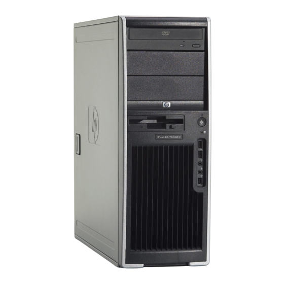
Product features Component view The following image shows a typical HP xw4400 workstation. Drive configurations can vary. For complete and current information on supported accessories and components, see http://partsurfer.hp.com. Figure 1-1 Component view Table 1-1 Component view Item Description Power supply... -
Page 13: Front Panel Components
Front panel components The following image shows a typical HP xw4400 Workstation. Drive configurations can vary. Figure 1-2 Front panel components Table 1-2 Front panel components Item Description Optical drive eject button Power on light Power button Hard drive activity light Universal Serial Bus 2.0 (USB) (x2) -
Page 14: Serial Number And Coa Label Location
Figure 1-3 Rear panel components Table 1-3 Rear panel components Item Description Power supply Built-In Self Test (BIST) LED Universal chassis clamp opening PS/2 mouse connector (green) Parallel connector (burgandy) Audio line-in connector (light blue) RJ-45 network connector Cable lock slot Padlock loop The rear panel connectors are labeled with industry-standard icons and colors to assist you in connecting your peripheral devices. - Page 15 Figure 1-4 Serial number and COA label location ENWW Product features...
-
Page 16: Product Specifications
Product specifications The following table lists the physical dimensions for the HP xw4400 Workstation. Table 1-4 Physical characteristics Weight (typical configuration) Tower dimensions Power supply This section describes power supply specifications for the HP xw4400 Workstation. ● +3.3V—PCI, PCI Express, audio, CK-410, ICH7R, super I/O, BIOS ROM, and on-board logic ●... -
Page 17: Power Supply Specifications
Power supply specifications Table 1-6 Power supply specifications Power supply Operating voltage range Rated voltage range Rated line frequency Operating line frequency range Rated input current Heat dissipation (Configuration and software dependent) Power Supply fan Energy Star compliant Blue Angel Compliant (<5w in S5 – Power Off) FEMP Standby Power Compliant @115V (<2W in S5 –... - Page 18 Table 1-7 Energy consumption (continued) Sleep (S3)* Power off (S5) * Values are approximate. NOTE To reach zero power consumption, disconnect the workstation from the power outlet or use a power strip to switch off the power. For additional information on power-saving features, see your operating system documentation. Table 1-8 Heat dissipation** Windows idle (SO)
-
Page 19: System Fans
Table 1-10 Heat dissipation** enabled Windows idle (SO) 399 btu/hr Windows busy (S0) 652 btu/hr Sleep (S3)* 11.3 btu/hr Power off (S5) 6.4 btu/hr * Energy Star lower energy mode. ** Heat dissipation is calculated based on the measured watts, assuming the service level is attained for one hour. This product is in compliance with US executive order 13221, WOL (wake on LAN) disabled. - Page 20 Table 1-11 Environmental specifications (continued) Vibration (operating) Vibration (non-operating) Chapter 1 Product overview NOTE Values represent individual shock events and are not indicative of repetitive shock events. Operating random: 0.5 G rms, 5–300 Hz Random: 2.0 G(rms), 10–500 Hz NOTE Values are not indicative of continuous vibration.
-
Page 21: Energy Star
Environmental Protection Agency (EPA) Computers Program. The EPA ENERGY STAR configuration does not imply endorsement by the EPA. As an ENERGY STAR partner, HP has determined that products with the ENERGY STAR configuration meet the ENERGY STAR guidelines for energy efficiency. -
Page 22: Hyper-Threading Technology
Configuration, click the Advanced tab, click Device Options and enable Hyper-Threading. If the HP Cool Tools icon is not on your desktop, click Start > All Programs > HP Cool Tools > HP Protect Tools Security Manager. Within HP Protect Tools Security Manager, select BIOS Configuration, click the Advanced tab, click Device Options and enable Hyper-Threading. -
Page 23: Dual-Core Cpus
Dual-core CPUs The HP xw4400 Workstation contains a dual-core processor. Like HT Technology, dual-core processors enable better performance over traditional processors. Dual-core processors provide the system with two true processors in a single socket, rather than the two "virtual" processors provided by HT Technology. -
Page 24: Hp Cool Tools
To access or learn more about these applications: ● Open the HP Cool Tools folder by selecting Start > All Programs > HP Cool Tools. ● Click the HP Cool Tools icon on the desktop. -
Page 25: Installing Or Restoring The Operating System
● HP software on page 19 ● Restoring the Windows operating system on page 20 ● HP Backup and Recovery Manager restore points on page 21 ● Protecting the software on page 22 ● Ordering backup software on page 23 If your workstation was shipped with a preinstalled operating system, it is configured automatically the first time your workstation is powered on. -
Page 26: Installing The Operating System And Software
This behavior is normal. The boot process continues its execution after the screen returns. Restoring the Linux operating system To restore the Linux operating system, the HP Driver CD and Red Hat box set are required. Download the latest HP Driver CD to get any new enhancements. -
Page 27: Downloading The Latest Hp Driver Cd Contents
Red Hat box set. The Installer kit includes the HP CDs necessary to complete the installation of all versions of the Red Hat box set that have been verified to work on HP workstation hardware. -
Page 28: Installing The Linux Operating System
Linux operating system on page 16 For more information concerning the setup of Linux-preinstalled or Linux-enabled workstations, refer to the HP User Manual for Linux located at http://www.hp.com/support/linux_user_manual. For more information about HP and Linux, see http://www.hp.com/linux. Chapter 2 Installing or restoring the operating system in this chapter. -
Page 29: Hp Software
HP software The following HP software may be installed on your workstation depending on the operating system and options: ● Computer Setup (F10) Utilities and diagnostic features ● HP Support Software including device drivers ● Security Management tools (optional) ●... -
Page 30: Restoring The Windows Operating System
CDs for RestorePlus!, the Windows operating system, and a supplemental HP Backup and Recovery Manager CD. (There may be additional CDs you can create depending on the options you purchased.) You also have the option to move images of the CDs to another location, such as a network share, to be burned to CD at a later time or from another system. -
Page 31: Hp Backup And Recovery Manager Restore Points
Restoring from the HP Backup and Recovery Manager restore point CD or DVDs The HP Backup and Recovery Manager (HPBR) restore point can be burned to CD or DVDs and used to restore the system. Typically you would used the CD/DVD set if the hard drive has been replaced or all partitions have been corrupted. -
Page 32: Protecting The Software
Protecting the software To protect software from loss or damage, keep a backup copy of all system software, applications, and related files stored on the hard drive. See the operating system or backup utility documentation for instructions on making backup copies of data files. Chapter 2 Installing or restoring the operating system ENWW... -
Page 33: Ordering Backup Software
Ordering backup software If you are unable to create system recovery CDs or DVDs, the HP Restore Plus CD set can be obtained through product support on http://www.hp.com/support. NOTE Before calling HP to order the software, be sure to have the serial number of your workstation available. - Page 34 Chapter 2 Installing or restoring the operating system ENWW...
-
Page 35: System Management
System management This section describes the various tools and utilities that allow for the system management of the workstation. ● Computer Setup (F10) Utility on page 26 ● Desktop management on page 34 ENWW... -
Page 36: Computer Setup (F10) Utility
Computer Setup (F10) Utility The Computer Setup (F10) Utility enables you to: ● Change factory default settings and set or change the system configuration, which might be necessary when you add or remove hardware. ● Determine if all of the devices installed on the workstation are recognized by the system and functioning properly. -
Page 37: Bios Rom
● Replicate your system setup by saving system configuration information on diskette and restoring it on one or more workstations. ● Execute self-tests on specified SATA and SAS hard drives (when supported by the drive). BIOS ROM The BIOS of the computer is a collection of machine language programs stored as firmware in ROM. The BIOS ROM includes such functions as POST, PCI device initialization, plug-in-play support, power management activities, and the Computer Setup (F10) Utility. -
Page 38: Computer Setup (F10) Utility Menu
Use the arrow (left and right) keys to select the appropriate heading. Use the arrow (up and down) keys to select the option you want, and press Enter. To apply and save changes, select File>Save Changes then select Exit. ● If you have made changes that you do not want applied, select Ignore Changes and Exit. - Page 39 Table 3-1 Computer Setup (F10) Utility menu descriptions (continued) Heading Option Ignore Changes and Exit Save Changes and Exit Storage Device Configuration Storage Options ENWW Description Exits Computer Setup without applying or saving any changes. Saves changes to system configuration and exits Computer Setup. Lists all installed non-SCSI storage devices and provides options for getting specific information about each device.
- Page 40 Table 3-1 Computer Setup (F10) Utility menu descriptions (continued) Heading Option DPS Self-test Boot Order Controller Order Security Setup Password Power-On Password Drivelock Security Smart Cover Device Security Network Service Boot Chapter 3 System management Description Enables/disables SATA controller #0. Secondary SATA Controller Enables/disables SATA controller #1.
- Page 41 Table 3-1 Computer Setup (F10) Utility menu descriptions (continued) Heading Option System IDs Data Execution Prevention Power OS Power Management Hardware Power Management Thermal Advanced Power-On Options Execute Memory Test BIOS Power-On ENWW Description Allows you to set: ● Asset tag (16-byte identifier) and ownership tag (80-byte identifier displayed during POST). ●...
- Page 42 Table 3-1 Computer Setup (F10) Utility menu descriptions (continued) Heading Option Onboard Devices PCI Devices Bus Options Device Options Slot 1 (PCI Express x 16) Slot 2 (PCI) Slot 3 (PCI Express x 8’ (x4)) Slot 4 (PCI Express x1) Slot 5 PCI Chapter 3 System management Description...
- Page 43 Table 3-1 Computer Setup (F10) Utility menu descriptions (continued) Heading Option Slot 6 PCI **These options should be used by advanced users only. ENWW Description Configures the option ROM and latency timer. Computer Setup (F10) Utility...
-
Page 44: Desktop Management
Updating the operating system, application software, or drivers To initiate a remote system installation, press F12 when the F12=Network Service Boot message appears in the lower-right corner of the HP logo screen. Follow the on-screen instructions to continue Chapter 3 System management (http://whp-sp-orig.extweb.hp.com/... -
Page 45: Updating And Managing Software
Altiris Client Management Solutions HP and Altiris have partnered to provide comprehensive, tightly integrated systems management solutions to reduce the cost of owning HP client PCs. HP Client Manager Software is the foundation for additional Altiris Client Management Solutions that address: ●... -
Page 46: System Software Manager
Subscriber’s Choice Subscriber’s Choice is a client-based service from HP. Based on your profile, HP will supply you with personalized product tips, feature articles, and driver and support alerts and notifications. Subscriber’s Choice Driver and Support Alerts/Notifications will deliver e-mails notifying you that the information you subscribed to in your profile is available for review and retrieval. -
Page 47: Rom Flash
Remote ROM Flash allows the system administrator to safely upgrade the ROM on remote HP workstations directly from the centralized network management console, resulting in a consistent deployment of and greater control over HP PC ROM images over the network. It also results in greater productivity and lower total cost of ownership. -
Page 48: Replicating The Setup
Insert a ROMPaq diskette into the diskette drive or, if permitted on this workstation, insert a ROMPaq CD into the CD drive. USB media such as an HP DriveKey can also be used. Power on the workstation. -
Page 49: Copying To A Single Workstation
A setup configuration is model-specific. File system corruption can result if source and target workstations are not the same model. For example, do not copy the setup configuration from an HP xw4200 Workstation to an HP xw4400 Workstation. Select a setup configuration to copy, and reboot the workstation. -
Page 50: Dual-State Power Button
World wide website HP engineers rigorously test and debug software developed by HP and third-party suppliers and develop operating system specific support software to ensure performance, compatibility, and reliability for HP workstations. -
Page 51: Building Blocks And Partners
HP has made the task of locating, accessing, evaluating, and installing the latest support software easier. You can download the software from http://www.hp.com/support. This website contains the latest device drivers, utilities, and flashable ROM images needed to run the latest Microsoft Windows operating system on the HP workstation. -
Page 52: Password Security
NOTE System Software Manager and HP Client Manager Software allow remote management of Setup Passwords and other BIOS settings in a networked environment. For more information, see http://www.hp.com/go/easydeploy. -
Page 53: Establishing A Power-On Password Using Workstation Setup
If a setup password has been established on the workstation, you will be prompted to enter it each time you run the Computer Setup (F10) Utility. ENWW Enter to bypass the title screen, if necessary. key at the appropriate time, you must restart the key again to access the utility. key until you enter the Computer Desktop management... -
Page 54: Changing A Power-On Or Setup Password
To enter a setup password: Restart the workstation. As soon as the workstation is powered on, press and hold the Setup (F10) Utility. Press NOTE If you do not press the workstation and press and hold the If you are using a PS/2 keyboard, you might see a Keyboard Error message—disregard it. When the key icon appears on the monitor, enter the setup password, and press Enter. -
Page 55: Deleting A Power-On Or Setup Password
National keyboard delimiter characters on page 45 Language Delimiter Greek Hebrew Hungarian Italian Japanese Korean Latin American Norwegian Polish Portuguese Enter to bypass the title screen, if section for information Language Delimiter Russian Slovakian Spanish Swedish/Finnish Swiss Taiwanese Thai Turkish U.K. English U.S. English Desktop management... -
Page 56: Clearing Passwords
ATA Security command set are detected. DriveLock is intended for HP customers for whom data security is the paramount concern. For such customers, the cost of the hard drive and the loss of the data stored on it is inconsequential when compared with the damage that could result from unauthorized access to its contents. -
Page 57: Using Drivelock
DriveLock. Since the initial configuration of DriveLock is typically performed by a system administrator, a master password should be set first. HP encourages system administrators to set a master password whether they plan to enable DriveLock or keep it disabled. This will give the administrator the ability to modify DriveLock settings if the drive is locked in the future. -
Page 58: Hood Sensor (Smart Cover Sensor)
In a single drive system, if the drive is drive-locked, then the system will most likely not boot to the operating system. The system may try to boot from the network instead, depending on the boot ordering options. Regardless, the drive-locked drive remains inaccessible without the DriveLock password. In a two drive system where there is a boot drive and a data drive, one can apply the DriveLock feature only to the data drive. -
Page 59: Locking The Solenoid Lock
Startup failure ● PC component failure (such as processor or power supply) ● Forgotten password CAUTION The side access panel FailSafe Key is a specialized tool available from HP. Be prepared; order this key before you need one. ENWW Desktop management... -
Page 60: Clearing Passwords
If the workstation is connected to a network managed by HP Client Manager Software, the computer sends a fault notice to the network management application. With HP Client Manager Software, you can also remotely schedule diagnostics to automatically run on all managed PCs and create a summary report of failed tests. -
Page 61: Drive Protection System
HP workstations. the DPS is designed to help diagnose problems that might result in unwarranted hard drive replacement. When HP workstations are built, each installed hard drive is tested using the DPS, and a permanent record of key information is written onto the drive. Each timethe DPS is run, test results are written to the hard drive. - Page 62 Chapter 3 System management ENWW...
-
Page 63: Removal And Replacement Procedures
Removal and replacement procedures This chapter describes removal and replacement procedures of most internal components. ● Service considerations on page 54 ● Customer Self-Repair on page 59 ● Predisassembly procedures on page 60 ● System board components on page 61 ●... -
Page 64: Service Considerations
Service considerations The following sections discuss service considerations that should be reviewed and practiced before removing and replacing any system components. WARNING! or lifting point. Lifting the workstation from the front bezel or lifting it incorrectly can cause the unit to fall and harm you and damage the workstation. -
Page 65: Preventing Electrostatic Damage To Equipment
Preventing electrostatic damage to equipment Many electronic components are sensitive to ESD. Circuitry design and structure determine the degree of sensitivity. The following packaging and grounding precautions are necessary to prevent damage to electric components and accessories. ● Transport products in static-safe containers, such as tubes, bags, or boxes, to avoid hand contact. ●... -
Page 66: Recommended Materials And Equipment
If an incorrect screw is used during the reassembly process, it can damage the unit. HP strongly recommends that all screws removed during disassembly be kept with the removed part, and then returned to their proper locations. -
Page 67: Special Handling Of Components
Lifting the workstation from the front bezel or lifting it incorrectly could cause the unit to fall and cause harm to the user and damage to the workstation. To properly and safely lift the workstation, lift it from the bottom of the unit from either the desktop or minitower configuration. Cables and connectors Cables must be handled with care to avoid damage. -
Page 68: Hard Drives
Hard drives Handle hard drives as delicate, precision components, avoiding all physical shock and vibration. This guideline applies to failed drives as well as replacement spares. ● If a drive must be mailed, place the drive in a bubble-pack mailer or other suitable protective packaging and label the package “Fragile: Handle With Care.”... -
Page 69: Customer Self-Repair
Customer Self-Repair Customer Self-Repair enables you to obtain replacement parts and install them yourself on your workstation. See http://www.hp.com/go/selfrepair/ ENWW for more information. Customer Self-Repair... -
Page 70: Predisassembly Procedures
Predisassembly procedures Perform the following steps before servicing the workstation: Close any open software applications. Remove any diskettes or CDs from the workstation. Shut down the operating system. Power off the workstation and any peripheral devices that are connected to it. Remove or disengage any security devices that prohibit opening the workstation. -
Page 71: System Board Components
System board components The following image shows the system board connectors and sockets on the HP xw4400 Workstation. Figure 4-2 System board identification Table 4-3 System board components Component Second serial port adapter Rear chassis fan Auxiliary power Processor Solenoid hood lock... -
Page 72: System Board Architecture
System board architecture The following image shows the HP xw4400 Workstation block diagram. Figure 4-3 System board block diagram Chapter 4 Removal and replacement procedures ENWW... -
Page 73: Steps For Removal And Replacement Of Components
Steps for removal and replacement of components This section discusses the procedures necessary to remove and install various hardware components on your workstation. Review the safety and precautions and the well as the Safety and Regulatory Information, before servicing or upgrading your system. Read all safety information and precautions. -
Page 74: Security Lock (Optional)
Security lock (optional) If a security padlock is installed, remove it before servicing the unit. To remove the padlock, unlock it and slide it out of the padlock loop as shown in the following image. Figure 4-4 Removing the security lock Chapter 4 Removal and replacement procedures Front fan removal (optional) -
Page 75: Cable Lock (Optional)
Cable lock (optional) If a cable lock is installed, remove it before servicing the unit. To remove the cable lock, unlock it and pull it out of the cable lock slot as shown in the following image. Figure 4-5 Removing the cable lock Universal chassis clamp lock (optional) If a universal chassis clamp lock is installed, remove it before servicing the unit. -
Page 76: Side Access Panel
Remove the screw attaching the lock to the chassis. Side access panel Before accessing the internal components of the workstation, the side access panel must be removed. To remove the side access panel: WARNING! is powered off and that the power cord is disconnected from the electrical outlet. Disconnect power from the system (Predisassembly procedures on page If necessary, unlock the side access panel. -
Page 77: Front Bezel
To replace the side access panel, align the bottom groove of the side access panel with the bottom edge of the chassis, rotate the side access panel toward the chassis and press firmly until the latch engages. Front Bezel Lift up on the two release snaps 1 located on the front bezel. Rotate the front bezel away 2 from the chassis to remove the bezel. -
Page 78: Hood Sensor (Smart Cover Sensor)
NOTE The bezel blanks are keyed to assist you in replacing the blanks. Also, the subpanel can be rotated 90 degrees to install the optical drives in desktop orientation if desired. Hood sensor (Smart cover sensor) To remove the hood sensor:... -
Page 79: Solenoid Hood Lock (Smart Cover Lock) (Optional)
Using the FailSafe key (T-15 wrench), unscrew the two screws 2 from the back of the chassis as shown in the following illustration. To purchase a FailSafe key, contact your authorized HP reseller or service provider or visit the HP web site for ordering information. - Page 80 Pull the front panel I/O device assembly out about two inches away 4 from the chassis. Pull the front panel cables through the chassis and out the front of the unit. You might have to slide the cables out one at a time. Figure 4-11 Removing the front panel I/O device assembly To replace the front panel I/O device assembly:...
-
Page 81: Power Button
Power button To remove the power button: Disconnect power from the system access panel (Side access panel on page and remove the front panel I/O device assembly Disconnect the power button assembly cable from the system board. Press in on the clips 1 that secure the power button to the chassis. Dislodge the metal clip from the chassis by rocking the power button back and forth. -
Page 82: Power Supply
Remove the four screws 2 securing the speaker to the chassis and lift the speaker out 3 of the chassis. Figure 4-14 Removing the speaker To replace the speaker, reverse the previous steps. Power supply To remove the power supply: Disconnect power from the system access panel (Side access panel on page... -
Page 83: System Fan Assembly
Figure 4-15 Removing the power supply To replace the power supply, reverse the previous steps. System fan assembly To remove the system fan assembly: Disconnect power from the system access panel (Side access panel on page Disconnect the fan plug 1 from the system board. . Remove the four screws 2 from the rear of the chassis with a Phillips screwdriver, and lift it 3 out of the chassis. -
Page 84: Memory
Supports dual-channel DIMMs Memory module requirements CAUTION HP only ships DIMMs that are electrically and thermally compatible with this product. Because third-party DIMMs might not be electrically or thermally compatible, they are not supported by HP. Chapter 4 Removal and replacement procedures (Predisassembly procedures on page 66). -
Page 85: Required Loading Order
NOTE DIMMs and their sockets are keyed for proper installation. Be sure these guides line up when installing DIMMs. ● Use only industry-standard, unbuffered, PC2–4200 (533MHz) or PC2–5300 (667 MHz) DIMMs. ● Match DIMM pairs by size and type Required loading order Use the following illustration as a guide for installing memory: ●... -
Page 86: Pci Slots
Figure 4-19 Installing a memory module PCI Slots This section contains information on PCI slots. Your workstation contains three PCI slots, one PCI Express x1 slot, one PCI Express x16 (4) slot, and one PCI Express x16 (usually used for high-end graphics. Figure 4-20 Identifying the PCI slots Table 4-4... -
Page 87: Pci Retainer
Table 4-4 PCI slots (continued) * In addition to these slot power specifications, the overall power consumption of the system (including I/O cards, processor, and memory) must not exceed the maximum ratings of the system power supply. PCI retainer For added protection, some cards have PCI retainers installed to prevent movement during shipping. To remove the PCI retainer: Disconnect power from the system access panel... -
Page 88: Pci Express
The PCI Express I/O slots can support other PCI Express cards with lesser bus bandwidth than what is physically defined for the slot. Use the following table to determine compatibility. Table 4-5 PCI Express compatibility matrix for xw4400 PCI Express x1 slot PCI Express x16 (x4) slot... - Page 89 If removing another type of PCI Express card, lift the card out of the chassis. You do not need to press in on the “hockey stick” lever. Install a PCI slot cover and close the PCI levers. If the PCI levers do not close, be sure all cards are properly seated and then try again.
-
Page 90: Pci
Close the PCI retention clamp 4 by rotating the clamp downward and pushing on the two green snaps down from the rear panel of the chassis. Figure 4-24 Installing the PCI card To remove a PCI card: Disconnect power from the system access panel (Side access panel on page on page... -
Page 91: Ieee-1394 (Optional)
To install a PCI card: Disconnect power from the system access panel (Side access panel on page on page 77), if installed. Lift the PCI levers 1 by first pressing down and then up. Remove the PCI slot cover 2. Lower the PCI 3 card into the chassis. -
Page 92: Front Pci Card Guide And Fan Removal (Optional)
Install a PCI slot cover and close the PCI levers. If the PCI levers do not closed, be sure all cards are properly seated and then try again. Figure 4-27 Removing the IEEE-1394 To install an IEEE-1394 card, reverse the previous steps. Front PCI card guide and fan removal (optional) NOTE The fan is only used for special configurations, but the card guide is used with all full-... -
Page 93: Battery
Unsnap the fan housing from the chassis 2 and lift it out of the chassis 3. Figure 4-28 Removing the front fan Remove the fan from the fan housing by applying outward pressure on the fan housing while pushing the fan out of the housing. Figure 4-29 Removing the fan from the card guide To replace the front fan, reverse the previous steps, but be sure that the airflow direction arrow on the... -
Page 94: Power Connections To Drives
CAUTION Before removing the battery, be sure your CMOS settings are backed up as all CMOS settings are lost when the battery is removed. To back up the CMOS settings, use Computer Setup and run the Save to Diskette option from the File menu. NOTE Batteries, battery packs, and accumulators should not be disposed of together with general household waste. - Page 95 Figure 4-31 Identifying the correct power connections for a typical configuration Main power on system board CPU power PCI Express graphic auxiliary PCI auxiliary (e.g. 1394) ODD IDE top bay ODD IDE mid bay 3rd HDD SATA bottom ODD bay 4th HDD SATA mid ODD bay ODD IDE or 3rd HDD SAS ODD bottom bay 1st HDD SATA bottom HDD bay...
-
Page 96: Optical Drive (Minitower Position)
Optical drive (Minitower position) To remove an optical drive: Disconnect power from the system access panel (Side access panel on page on page 67). Disconnect the audio 1, data 2, and power 3 cables from the drive. The connector colors might be different than illustrated. - Page 97 After pulling the drive 1 out, remove the four guide screws 2 from the drive. Only remove the four guide screws if you plan to install another drive. Figure 4-34 Removing the optical drive screws To install an optical drive: Disconnect power from the system access panel (Side access panel on page...
-
Page 98: Optical Drive (Desktop Position)
NOTE The audio cable is only required for Linux-based systems. Figure 4-35 Connecting the optical drive cable to the system board Optical drive (Desktop position) To remove an optical drive: Disconnect power from the system access panel (Side access panel on page on page 67). - Page 99 Press down on the yellow drive-lock release lever 1 and gently slide the drive 2 out of the chassis. Figure 4-37 Removing the optical drive from the chassis After pulling the drive 1 out, remove the four guide screws 2 from the drive. Only remove the four guide screws if you plan to install another drive.
-
Page 100: Diskette Drive (Optional)
Connect the power, drive, and audio (if required) cables to the drive and system board. On Linux systems, connect the audio cable to the AUX-IN connector. NOTE The audio cable is only required for Linux-based systems. Figure 4-39 Connecting the optical drive cable to the system board Diskette drive (optional) To remove a diskette drive: Disconnect power from the system... -
Page 101: Sas Hard Drive
Lift the green drive-lock release tab 1 and gently slide the drive 2 out at the same time. Figure 4-41 Removing the diskette drive from the chassis To replace a diskette drive: Align the metal protrusions on the side of the drive with the grooves in the diskette drive bay and slide the diskette drive into the bay until it stops. - Page 102 Disconnect the data 1 and power 2 cables from the hard drive. Figure 4-42 Removing the hard drive Lift up on the green drive-lock release tab 1 and slide the hard drive 2 out of the chassis. Figure 4-43 Removing the hard drive To install a SAS hard drive: Disconnect power from the system access panel...
- Page 103 Attach a SAS-to-SATA cable adapter to the connector on the hard drive. Figure 4-44 Attaching the adapter Push the drive 1 into the selected bay until it snaps into place. Attach the data 2 and power 3 cables to the drive. Figure 4-45 Installing the SAS hard drive Insert the SAS controller card into an available PCI slot.
-
Page 104: Sata Hard Drive
Connect the hard drive LED cable from the card to the hard drive LED connector on the system board. You can find the location of this connector on the illustration on the inside of the side access panel. Figure 4-46 Connecting the SAS cable to the hard drive SATA hard drive For more information on SATA hard drives and the SATA RAID configurations, refer to the SATA devices... - Page 105 Lift up on the green drive-lock release tab 1 and slide the hard drive 2 out of the chassis. Figure 4-48 Removing the hard drive To install one or two SATA hard drives: Disconnect power from the system access panel (Side access panel on page Select a drive bay in which to install the drive.
-
Page 106: Installing Hard Drives In The Optical Drive Bays (Optional)
Connect the data cable from the hard drive 1 to the serial ATA port 2. SATA0 port is shown in the following illustration. ● Connect SATA 0 to SATA0. ● Connect SATA 1 to SATA1. Figure 4-50 Connecting the SATA cable to the hard drive To install three to four SATA hard drives: Follow the instructions for installing two SATA hard drives above. - Page 107 Place the hard drive in the bracket 1 and secure with American National screws 2 as shown in the following illustration. Figure 4-51 Installing hard drive into bracket Screw four screws to the bracket 1. Align the screws with the grooves in the optical drive bay and slide the drive in 2 the chassis.
-
Page 108: Cpu Heatsink
Connect the power cables (not shown). Figure 4-53 Connecting the data cable to the system board CPU heatsink NOTE The following illustrated CPU heatsink is typical of what you might have in your workstation. Be aware that different variations of the CPU heatsinks exist, but the overall procedures listed are sufficient to assist you in removing the CPU heatsink. - Page 109 Loosen the four processor screws slowly and evenly. Loosen one pair of diagonally opposite screws 1 until the screw shanks disengage from the system board, and then loosen the remaining pair 2. Do not fully loosen one screw, and then move on to the next. Loosen all of the screws a little at a time, being sure the processor remains level.
-
Page 110: Processor
To replace the CPU heatsink: Disconnect power from the system access panel (Side access panel on page Use alcohol and a soft cloth to clean all of the thermal interface residue from the CPU heatsink and processor. CAUTION Check for proper processor seating in the socket by carefully trying to lift the processor out of the socket with your fingers. - Page 111 Pull the processor 3 straight out of the socket. . Figure 4-56 Raising the processor socket handle CAUTION Avoid bending the protrusions in the CPU socket. This mishandling can damage the CPU socket. NOTE Store the processor in a safe place where it will not be damaged. To replace the processor: Disconnect power from the system access panel...
-
Page 112: System Board
Align the triangle on the top of the processor with the triangle on the corner of the processor socket and install the processor into the socket. Ensure that the underside of the processor is level with the top of the processor socket. Lightly press down on the top of the processor while closing the socket lever. - Page 113 Slide the system board toward the front of the chassis and then lift it 2 out of the unit. . Figure 4-58 Removing the system board To replace the system board: Lay the system board back in the chassis slightly away from the rear of the chassis. The mounting hooks should fall into the recesses of the tray so the tray lays flat on the chassis base.
- Page 114 Chapter 4 Removal and replacement procedures ENWW...
-
Page 115: System Diagnostics And Troubleshooting
E-Support on page 106 ● Troubleshooting checklist on page 107 ● LED color definitions on page 108 ● HP Insight Diagnostics Offline Edition on page 109 ● Diagnostic error codes on page 114 ● Troubleshooting scenarios and solutions on page 117 ●... -
Page 116: E-Support
To open HSC from your desktop, click Start>Help and Support. HSC contains four sections: ● HP Product Information (requires Internet access)—Links to the HP Technical Support website for your product. You can access all related documentation, downloads and updates, tools, and more. ●... -
Page 117: Troubleshooting Checklist
Troubleshooting checklist Before running any of the diagnostic utilities, use the following checklist to find possible solutions for workstation or software problems. ● Are the workstation and monitor connected to a working electrical outlet? ● Is the workstation powered on? ●... -
Page 118: Led Color Definitions
LED color definitions An LED light exists on the front panel of your workstation. The following table describes what each color signifies. Table 5-1 LED color definitions LED state Solid Flashing Solid or flashing None Chapter 5 System diagnostics and troubleshooting LED color Green Green... -
Page 119: Hp Insight Diagnostics Offline Edition
You can select tests that do not require any user interaction through the Interactive and Unattended tests modes. Diagnostic Utility on CD HP Insight Diagnostics is available on the Documentation Library CD that was shipped with your workstation. ENWW... -
Page 120: Downloading The Latest Diagnostic Utility
Access http://www.hp.com. Click the Support & Drivers link. Select the Download driver and software radio button. Enter your product number (for example, xw4400) in the text box and press the Select your operating system. Click the Diagnostic link. Locate HP Insight Diagnostics Offline and click Download. -
Page 121: Test Tab
If you want to run the diagnostic test for a specified time period, enter the amount of time in minutes. Click Begin Testing in the lower right corner of the display to start the test. ENWW HP Insight Diagnostics Offline Edition... -
Page 122: Status Tab
While tests are being performed, you can monitor the progress by viewing the Status tab. Any errors that are detected are summarized in the Error Log. Select Save to save the report to floppy or a USB Key Drive if attached. If the diagnostics utility detects an error during a test, the user can mouse-over the failed text in the Status tab to display additional information for the type of error and the error code. -
Page 123: Help Tab
Help tab The Help tab has three views: ● HP Insight Diagnostics—Provides introductory and detailed information about Insight Field Diagnostics. ● Error Codes—Provides error code listings. It includes device tested, message, and recommended repair information. ● Test Components—Reloads and refreshes all components and display component details after the refresh. -
Page 124: Diagnostic Error Codes
Diagnostic error codes This sections provides an overview of the diagnostic LEDs and error codes that are related to your workstation. Diagnostic LED codes NOTE The beeps are heard through the on-board piezo speaker and not the chassis speaker. The flashing lights and beeps repeat for five cycles. After that, only the flashing lights repeat. Table 5-2 Diagnostic LED codes Chassis indicator LEDs... - Page 125 Pre-video memory error. Reseat memory modules. Replace memory modules one at a time to find the faulty module. Replace third-party modules with HP memory. Replace system board. Pre-video graphic card error. For systems with integrated graphics, replace system board.
- Page 126 Table 5-2 Diagnostic LED codes (continued) Chassis indicator LEDs Power LED and sound activity Blinks red 8 times, once per second, then 2-second pause, 8 beeps Blinks red 9 times, once per second, then 2-second pause, 9 beeps Chapter 5 System diagnostics and troubleshooting Diagnosis and service action Invalid ROM based on bad checksum.
-
Page 127: Troubleshooting Scenarios And Solutions
Troubleshooting scenarios and solutions This section presents an extensive overview of various troubleshooting scenarios and includes possible solutions for each. Solving minor problems Table 5-3 Minor problems Problem Workstation appears locked up and will not shut down when the power button is pressed. Workstation seems to be locked up. -
Page 128: Solving Power Supply Problems
Table 5-3 Minor problems (continued) Problem Solving power supply problems Testing power supply Before replacing the power supply, use the Built-In Self-Test (BIST) feature to learn if the power supply still works. To test the power supply: Unplug the AC power. Disconnect all internal power supply cables from the system board. - Page 129 Figure 5-1 Testing power supply with BIST LED Table 5-4 Power supply problems Problem Power supply shuts down intermittently. ENWW Cause Solution Power supply fault. Replace the power supply. Troubleshooting scenarios and solutions...
-
Page 130: Solving Diskette Problems
Table 5-4 Power supply problems (continued) Problem Workstation powered off automatically and the Power LED flashes red 2 times, once every second, followed by a 2-second pause. Power LED flashes red, once every 2 seconds. Solving diskette problems Table 5-5 Diskette problems Problem Diskette drive light stays on. - Page 131 Table 5-5 Diskette problems (continued) Problem Diskette drive cannot write to a diskette. Cannot format diskette. A problem has occurred with a disk transaction. Diskette drive cannot read a diskette. “Invalid system disk” message is displayed. Cannot Boot to Diskette. ENWW Cause Solution...
-
Page 132: Solving
Solving Table 5-6 Hard drive problems Problem Hard drive error occurs. Disk transaction problem. Drive not found (identified). Nonsystem disk/NTLDR missing message. Nonsystem disk/NTLDR missing message. Second Ultra ATA hard drive does not perform optimally. Workstation will not start. Chapter 5 System diagnostics and troubleshooting Cause Solution Hard disk has bad sectors or... -
Page 133: Solving Display Problems
Solving display problems Table 5-7 Display problems Problem Blank screen (no video). The display works properly during the POST but goes blank when the operating system starts. Power LED flashes red 6 times, once every second, followed by a 2–second pause, and the workstation beeps 6 times. -
Page 134: Solving Audio Problems
Table 5-7 Display problems (continued) Problem Blurry video or requested resolution cannot be set. The picture is broken up, rolls, jitters, or flashes. Vibrating or rattling noise coming from inside a CRT monitor when powered on. Clicking noise coming from inside a CRT monitor. -
Page 135: Solving Printer Problems
Table 5-8 Audio problems (continued) Problem Noise or no sound comes out of the speakers or headphones. NOTE If you set digital as the Output Mode, the internal speaker and external analog speakers will no longer output audio until you switch back to an auto-sense or analog mode. If you set analog as the Output Mode, external digital speakers will not function until you change the output mode back to an auto-sense or digital mode. -
Page 136: Solving Keyboard And Mouse Problems
Table 5-9 Printer problems (continued) Problem Printer does not turn on. Printer prints garbled information. Printer is offline. Solving keyboard and mouse problems Table 5-10 Keyboard and mouse problems Problem Keyboard commands and typing are not recognized by the workstation. Cursor will not move using the arrow keys on the keypad. -
Page 137: Solving Front Panel Component Problems
The port is not there because it You can buy an IEEE 1394 PCI adapter card. Contact an was not purchased with the HP seller. system. Troubleshooting scenarios and solutions... -
Page 138: Solving Hardware Installation Problems
Reseat DIMMs. or is bad. Replace DIMMs one at a time to isolate the faulty module. Replace third-party memory with HP memory. Replace the system board. Video card is not seated For systems with a graphic card: properly or is bad, or system Reseat the graphics card. -
Page 139: Solving Network Problems
Solving network problems These guidelines do not discuss the process of debugging the network cabling. Table 5-13 Network problems Problem Wake-on-LAN feature is not functioning. Network driver does not detect network controller. Network status link light does not illuminate or it never flashes. The network status light should flash when there is network activity. -
Page 140: Solving Memory Problems
System setup utility reports unprogrammed EEPROM. Solving memory problems CAUTION For those systems that support ECC memory, HP does not support mixing ECC and non-ECC memory. Otherwise, the system will not boot the operating system. Table 5-14 Memory problems Problem... -
Page 141: Solving Processor Problems
DVD-R/RW drive cannot read a disc or takes too long to start. ENWW Cause Solution Replace third-party memory with HP memory. Replace the system board. Cause Solution Processor is hot. Be sure the airflow to the workstation is not blocked. -
Page 142: Solving Internet Access Problems
Table 5-16 CD-ROM and DVD problems (continued) Problem Recording audio CDs is difficult or impossible. Solving Internet access problems Table 5-17 Internet access problems Problem Unable to connect to the Internet. Cannot automatically launch Internet programs. Internet takes too long to download websites. - Page 143 Table 5-17 Internet access problems (continued) Problem ENWW Cause Solution In the Device Manager area, click the Device Manager button. Double-click Ports (COM & LPT). Right-click the COM port your modem uses, then click Properties. Under Device status, verify that the modem is working properly.
-
Page 144: Post And Error Messages
POST and error messages POST is a program run at startup that initializes and runs some tests on installed hardware. An audible and/or visual message occurs if the POST encounters a problem. POST checks the following items to ensure that the workstation system is functioning properly: ●... - Page 145 Be sure memory modules (if any) are installed properly. If third-party memory has been added, test using HP memory only. Verify proper memory module type. Reset system board jumpers to match processor and bus speeds (select models). Run Computer Setup (F10 Setup) or Windows utilities.
- Page 146 Table 5-18 POST error messages (continued) Screen message 214—DIMM Configuration Warning 215—Memory Mismatch Warning 216—Memory Size Exceeds Maximum Supported 219—ECC Memory Module Detected. 301—Keyboard Error 303—Keyboard Controller Error 304—Keyboard or System Unit Error 401—Parallel Port 1 Address Assignment Conflict 402—Parallel Port 2 Address Assignment Conflict 403—Parallel Port 3 Address Assignment Conflict...
- Page 147 Table 5-18 POST error messages (continued) Screen message 501—Display Adapter Failure 510—Splash Screen image corrupted 511—CPU, CPUA, or CPUB Fan not detected 512—Chassis, rear chassis, or front chassis fan not detected 514—CPU or Chassis Fan not detected 601—Diskette Controller Error Diskette controller circuitry or diskette 605—Diskette Drive Type Error 610—External Storage Device...
- Page 148 Table 5-18 POST error messages (continued) Screen message 917—Front Audio Not Connected 918—Front USB Not Connected 919—MultiBay Riser Not Connected 920—Fan Command 2 Pin Connector from Power Supply Not Connected 940—Extended ROM signature not found 960—CPU Overtemp occurred 1151—Serial Port 1 Address Conflict Detected 1152—Serial Port 2 Address Conflict Detected...
- Page 149 Run the Drive Protection System test if applicable. Apply firmware patch if applicable (see http://www.hp.com/support). Back up contents and replace hard drive. Be sure that any jumpers are set correctly, and that power and drive cables are connected, both to the drive and the system board.
- Page 150 Replace the system board. Upgrade BIOS to proper version. Replace the processor with a compatible one. Install the latest BIOS downloaded from http://www.hp.com. Run Computer Setup and save the MBR of the current bootable disk. Use extreme caution. The MBR might have been updated due to normal disk maintenance activities (disk manager, fdisk, or format).
- Page 151 Recommended action Run Computer Setup. If Setup already has data in the field or will not allow the serial number to be entered, download from http://www.hp.com and run the utility SP5572.EXE (SNZERO.EXE). Run Computer Setup and try to enter serial number under Security, System ID, and save the changes.
- Page 152 Chapter 5 System diagnostics and troubleshooting ENWW...
-
Page 153: Appendix A Appendix A - Sas Devices
Appendix A — SAS devices ENWW... -
Page 154: Supported Sas Raid Configurations
Internal-to-external cable for external connections ● SAS to SATA data and power converter ● LSI MyStorage Utility for Windows The following RAID configurations are supported on the HP xw6400 Workstation: ● RAID 0 – Striped disk array ● Two drives minimum ●... -
Page 155: Sas Raid 0 Configuration
SAS RAID 0 configuration Follow the steps below to configure an Integrated Striped (IS) volume with the BIOS-based configuration utility. The configuration procedure assumes that the system already has the required disk and disk controllers. On the Main menu screen of the BIOS-based configuration utility, use the arrow keys to select an adapter. -
Page 156: Sas Raid 1 Configuration
SAS RAID 1 configuration Follow the steps below to configure an Integrated Mirroring (IM) volume with the BIOS-based configuration utility. The configuration procedure assumes that the system already has the required disk and disk controllers. On the Main menu screen of the BIOS-based configuration utility, use the arrow keys to select an adapter. - Page 157 (Optional) Use the arrow keys to select a hot spare disk for the IM volume. Select Yes as the value for the Hot Spare column. When you have selected all disks for the IM volume, press Esc and select Save changes, then exit this menu.
-
Page 158: Sas Raid 1E Configuration
SAS RAID 1E configuration Follow the steps below to configure an Integrated Mirroring Extended (IME) volume with the BIOS-based configuration utility. The configuration procedure assumes that the system already has the required disk and disk controllers. On the Main menu screen of the BIOS-based configuration utility, use the arrow keys to select an adapter. - Page 159 (Optional) Use the arrow keys to select a hot spare disk for the IME volume. Select Yes as the value for the Hot Spare column. When you have selected all disks for the IME volume, press Esc and select Save changes, then exit this menu.
- Page 160 Appendix A Appendix A — SAS devices ENWW...
-
Page 161: Appendix B Appendix B - Sata Devices
Appendix B — SATA devices This appendix describes how to use the Intel Matrix Storage Manager option ROM Configuration Utility to set up and manage SATA RAID volumes. NOTE If only a single HDD is attached, the Intel Matrix Storage Manager option ROM will not execute. -
Page 162: Attaching Sata Hdds
Attaching SATA HDDs Attach the required number of SATA HDDs for the desired RAID level. ● RAID 0: Two to three HDDs ● RAID 1: Two HDDs ● RAID 5: Three HDDs Appendix B Appendix B — SATA devices ENWW... -
Page 163: Configuring System Bios
Configuring system BIOS Configure the system BIOS to enable embedded SATA RAID functionality. Press F10 to enter the system BIOS setup. Use the arrow keys to highlight the desired language, then press Enter. Use the arrows on your keyboard to highlight Storage>Storage Options, then press Enter. Use the up or down arrow key to highlight SATA Emulation. -
Page 164: Creating Raid Volumes
Creating RAID volumes Use the Intel Matrix Storage Manager option ROM Configuration Utility to create RAID volumes. Press Ctrl+I when prompted to enter the Intel Matrix Storage Manager option ROM Configuration Utility. If required, see create the desired RAID volume. Use the up or down arrow key to highlight 1. -
Page 165: Deleting Raid Volumes
Deleting RAID volumes Use the Intel Matrix Storage Manager option ROM Configuration Utility to delete RAID volumes. Use the up or down arrow key to highlight 2. Delete RAID Volume, and press Enter. Use the up or down arrow key to highlight the RAID volume to be deleted, and press Del. When prompted, press Y to confirm the deletion of the selected RAID volume. - Page 166 Appendix B Appendix B — SATA devices ENWW...
-
Page 167: Appendix C Appendix C - Connector Pins
Appendix C — Connector pins ENWW... -
Page 168: Connector Pin Descriptions
Connector pin descriptions Keyboard connector Mouse connector Ethernet connector Appendix C Appendix C — Connector pins Signal Data Unused Ground +5 VDC Clock Unused Signal Data Unused Ground +5 VDC Clock Unused Signal (+) Transmit Data (-) Transmit Data (+) Receive Data Unused Unused (-) Receive Data... - Page 169 Parallel connector Signal Strobe Data Bit 0 Data Bit 1 Data Bit 2 Data Bit 3 Data Bit 4 Serial connector USB connector IEEE 1394 connector ENWW Signal Data Bit 5 Data Bit 6 Data Bit 7 Acknowledge Busy Paper End Signal Select Auto Linefeed...
- Page 170 Microphone connector (1/8 inch) Headphone connector (1/8 inch) Line-in audio connector (1/8 inch) Line-out audio connector (1/8 inch) Appendix C Appendix C — Connector pins power tpb- tpb+ tpa- tpa+ Signal 1 (Tip) Audio 2 (Ring) Power 3 (Shield) Ground Signal 1 (Tip) Audio_Left...
- Page 171 SATA connector Signal Data Cable Ground Ground S5** S6** Ground * S2 and S3 differential signal pair **S5 and S6 differential signal pair SAS connector Segment Primary signal segment ENWW Signal Power Cable 3.3-V power 3.3-V power 3.3-V power Ground Ground Ground 5-V power...
- Page 172 SAS connector Segment Secondary signal segment Power segment Appendix C Appendix C — Connector pins Backplane receptacle SIGNAL GROUND SIGNAL GROUND SIGNAL GROUND precharge GROUND GROUND GROUND precharge GROUND READY LED GROUND precharge Plug and cable receptacles ENWW...
- Page 173 VGA connector Signal 1 2 3 Red Analog Green Analog Blue Analog Monitor ID Ground DVI connector T.M.D.S DATA 2- T.M.D.S DATA 2+ T.M.D.S DATA 2/4 SHIELD T.M.D.S DATA 4- T.M.D.S DATA 4+ 2 DDC CLOCK DDC DATA ANALOG VERT. SYNC T.M.D.S DATA 1- T.M.D.S DATA 1+ T.M.D.S DATA 1/3 SHIELD...
- Page 174 ATA/ATAPI (IDE) standard drive cable connector Signal 1 2 3 Reset Ground DD7 DD8 DD6 6 7 8 DD9 DD5 DD10 9 10 DD4 DD11 11 12 DD3 DD12 DD2 13 14 DD13 24-Pin Main power connector P1 +3.3 V +3.3 V +5 V +5 V...
- Page 175 6-Pin power (auxiliary system board) connector P8 8-Pin power (for CPUs and memory) P3 CAUTION Be sure you can differentiate between which power cable connects to the PCI Express x16 graphics card and which power cable connects to the system board. These two cables have different pin counts and different colors.
- Page 176 6-Pin power (auxiliary PCI Express) Appendix C Appendix C — Connector pins Color Signal +12V-C +12V-C +12V-C ENWW...
-
Page 177: Appendix D Appendix D - System Board Designators
Appendix D — System board designators This appendix lists the system board designators for this system. Designator MH02-03, MH06-09, MH14-15 BBLK_WP PSWD SLOT 5 PCI SLOT 6 PCI SLOT 4 SLOT4 PCIe x1 SLOT3 PCIe x16 (4) SLOT1 PCIe x16 P60-63, P66-67 SATA0, SATA1, SATA2 J50, P53... - Page 178 Designator INT USB HDD LED CONTROL PANEL CPUFAN1 CPU2FAN MEM FAN P130 CHASSIS FAN XBT2 XMM1 DIMM1 XMM2 DIMM3 XMM3 DIMM2 XMM4 DIMM4 RECOVER Appendix D Appendix D — System board designators Silkscreen Internal USB header HDD LED connector Main power/HDD LED/internal speaker connector Primary CPU fan header Secondary CPU fan header...
-
Page 179: Appendix E Appendix E - Routine Care
Appendix E — Routine care ENWW... -
Page 180: General Cleaning Safety Precautions
General cleaning safety precautions ● Never use solvents or flammable solutions to clean the workstation. ● Never immerse any component in water or cleaning solutions; apply any liquids to a clean cloth and then use the cloth on the component. ●... -
Page 181: Maximizing The Airflow
Maximizing the airflow ● Keep your workstation in an area where the airflow is not obstructed. ● Keep the unit off of surfaces where dust can gather. ● Keep the front of the unit clear of any obstruction. ● Remove any dust on the front panel (vent area) and the rear fans with a small vacuum, compressed air, or dust rag. -
Page 182: Cleaning The Workstation Case
Cleaning the workstation case ● Follow the safety precautions presented in before cleaning the workstation. ● To remove light stains or dirt, use plain water with a clean, lint-free cloth or swab. ● For stronger stains, use a mild dish-washing liquid diluted with water. Rinse well by wiping it with a cloth or swab dampened with clear water. -
Page 183: Cleaning The Keyboard
Cleaning the keyboard CAUTION Use safety glasses equipped with side shields before attempting to clean debris from under the keys. ● Follow the safety precautions presented in keyboard. ● Visible debris underneath or between the keys can be removed by vacuuming or shaking. ●... -
Page 184: Cleaning The Monitor
Cleaning the monitor ● Follow the safety precautions presented in keyboard. ● To clean the monitor, wipe the monitor screen with a towelette designed for cleaning monitors or a clean cloth moistened with water. CAUTION the housing and damage a component. Never use solvents or flammable liquids on the monitor because display or housing damage may result. -
Page 185: Cleaning The Mouse
Cleaning the mouse Follow the safety precautions presented in mouse. Remove the mouse ball from the housing by removing the retaining plate. Clean the mouse ball. Pull out any debris from the ball socket, and wipe the ball with a clean, dry cloth. Reassemble the mouse. - Page 186 Appendix E Appendix E — Routine care ENWW...
-
Page 187: Appendix F Appendix F - Additional Password Security And Resetting Cmos
Appendix F — Additional password security and resetting CMOS This workstation supports the following security password features, which can be established through the Computer Setup Utilities menu: ● Setup password ● Power-on password When you establish a setup password, only the power-on password is required to access Computer Setup and any other information on the workstation. -
Page 188: Resetting The Password Jumper
Resetting the password jumper To disable the power-on or setup password features and clear the power-on and setup passwords: Shut down the operating system, and power off the workstation and any external devices. Disconnect the power cord of the workstation and any external devices from the power outlets. Disconnect the keyboard, monitor, and any other external devices that are connected to the workstation. -
Page 189: Clearing And Resetting The Cmos
Clearing and Resetting the CMOS The CMOS of the workstation stores password information and information about the workstation configuration. This section describes the steps to successfully clear and reset the CMOS. Using the CMOS Button Shut down the operating system, and power off the workstation and any external devices. Disconnect the workstation power cord and any external devices from the power outlets. -
Page 190: Using Computer Setup To Reset Cmos
Using Computer Setup to Reset CMOS To reset CMOS using Computer Setup, access the Computer Setup (F10) Utilities menu. When the Computer Setup message appears in the lower-right corner of the screen, press the F10 key. Press Enter to bypass the title screen, if necessary. NOTE If you do not press the must be powered off, then on again, to access the utility. -
Page 191: Appendix G Appendix G - Quick Troubleshooting Flowcharts
Appendix G — Quick troubleshooting flowcharts This appendix presents some quick troubleshooting flowcharts for the following issues: ● Initial troubleshooting ● No power ● No video ● Error messages ● No OS loading ● No OS loading from hard drive ●... -
Page 192: Initial Troubleshooting
Initial troubleshooting Appendix G Appendix G — Quick troubleshooting flowcharts ENWW... -
Page 193: No Power
No power No power, part 1 ENWW No power... -
Page 194: No Power, Part 2
No power, part 2 Appendix G Appendix G — Quick troubleshooting flowcharts ENWW... - Page 195 No power, part 3 ENWW No power...
-
Page 196: No Video
No video No video, part 1 Appendix G Appendix G — Quick troubleshooting flowcharts ENWW... -
Page 197: No Video, Part 2
No video, part 2 ENWW No video... - Page 198 No video, part 3 Appendix G Appendix G — Quick troubleshooting flowcharts ENWW...
-
Page 199: Error Messages
Error messages Error messages, part 1 ENWW Error messages... -
Page 200: Error Messages, Part 2
Error messages, part 2 Appendix G Appendix G — Quick troubleshooting flowcharts ENWW... - Page 201 Error messages, part 3 ENWW Error messages...
-
Page 202: No Operating System Loading
No operating system loading Appendix G Appendix G — Quick troubleshooting flowcharts ENWW... -
Page 203: No Operating System Loading From Hard Drive
No operating system loading from hard drive No operating loading from hard drive, part 1 ENWW No operating system loading from hard drive... -
Page 204: No Operating System Loading From Hard Drive, Part 2
No operating system loading from hard drive, part 2 Appendix G Appendix G — Quick troubleshooting flowcharts ENWW... - Page 205 No operating system loading from hard drive, part 3 ENWW No operating system loading from hard drive...
-
Page 206: No Operating System Loading From Diskette Drive
No operating system loading from diskette drive Appendix G Appendix G — Quick troubleshooting flowcharts ENWW... -
Page 207: No Operating System Loading From Cd-Rom Drive
No operating system loading from CD-ROM drive ENWW No operating system loading from CD-ROM drive... -
Page 208: No Operating System Loading From Network
No operating system loading from network Appendix G Appendix G — Quick troubleshooting flowcharts ENWW... -
Page 209: Non-Functioning Device
Non-functioning device ENWW Non-functioning device... - Page 210 Appendix G Appendix G — Quick troubleshooting flowcharts ENWW...
Need help?
Do you have a question about the xw4400 and is the answer not in the manual?
Questions and answers