
Related Manuals for Eagle CUDA 350 S/MAP


Summary of Contents for Eagle CUDA 350 S/MAP
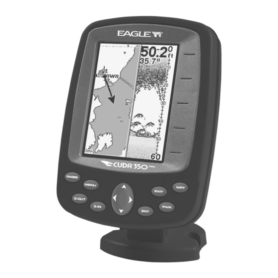
- Page 1 Pub. 988-0152-32A www.eaglesonar.com Fish-finding Sonar & GPS Installation and Operation Instructions...
- Page 2 350 S/Map is a registered trademark of Navico. ® ® Eagle Electronics may find it necessary to change or end our policies, regulations, and special offers at any time. We reserve the right to do so without notice. All features and specifications subject to change without notice.
-
Page 3: Table Of Contents
Section 1: Read Me First! ... 1 Capabilities and Specifications: Cuda 350 S/Map ... 3 How Your Sonar Works ... 5 How Your GPS Works... 6 Introduction to GPS and WAAS... 7 How to use this manual: typographical conventions ... 9 Arrow Keys ... - Page 4 Sensitivity & Auto Sensitivity... 72 Automatic Sensitivity ... 73 Set Keel Offset... 74 Sonar Color Mode... 76 Sonar Page & Sonar Chart Display Options ... 76 Full Sonar Chart ... 76 Split Zoom Sonar Chart ... 77 Digital Data/Chart ... 78...
- Page 5 Stop Chart ... 79 Surface Clarity ... 80 Zoom Pan ... 82 Section 5: Sonar Troubleshooting ... 83 Section 6: Basic GPS Operations ... 87 Keyboard... 87 Power/lights on and off ... 88 Main Menu ... 89 Pages ... 90 Sonar Page ...
- Page 6 Delete an Icon... 116 Navigate to an Icon ... 117 Routes ... 118 Create and Save a Route ... 118 Delete a Route ... 121 Edit a Route... 121 Navigate a Route... 122 Trails ... 124 Delete a Trail... 124 Edit a Trail Name ...
- Page 7 Map Data ... 139 Earth Map Detail ... 139 Pop-up Map Info ... 139 Fill Water With White ... 139 Map Overlays (Range Rings; Lat/Long Grid)... 140 Map Datum Selection ... 140 Map Detail Category Selection... 141 Map Orientation... 142 Overlay Data ...
- Page 8 A CAREFUL NAVIGATOR NEVER RELIES ON ONLY ONE METHOD TO OBTAIN POSITION INFORMATION. When showing navigation data to a position (waypoint), a GPS unit will show the shortest, most direct path to the waypoint. It provides navigation data to the waypoint regardless of obstructions.
-
Page 9: Section 1: Read Me First
GPS receiver. First, we want to thank you for buying a Eagle sonar/GPS unit. Whether you're a first time user or a professional fisherman, you'll dis- cover that your unit is easy to use, yet capable of handling demanding navigation and sonar tasks. - Page 10 Reference on page 50 and head for the water with your unit!) When you come to a sonar menu command on the unit's screen, you can look it up in the manual by skimming over the table of contents, looking it up in the manual's index, just flipping through Section 3 or scanning through the sonar setup options in Section 7.
-
Page 11: Capabilities And Specifications: Cuda 350 S/Map
It's important to us (and our power users), but, if you don't care how many watts of power the unit has, or how many waypoints it can store, skip ahead to important information on how sonar works, on page 5. Capabilities and Specifications: Display: ...High Contrast Film SuperTwist LCD with... - Page 12 The storage and operation temperature range for your unit is from pends on transducer configuration and instal- lation, bottom composition and water condi- tions. All sonar units typically read deeper in fresh water than in salt water. location with special icon, then automatically...
-
Page 13: How Your Sonar Works
The whole process repeats itself several times each second. Your sonar unit can record a log of the sonar signals that scroll across the screen and save them in its memory. (These recordings are also called... -
Page 14: How Your Gps Works
You can replay this sonar log in the unit using the Sonar Simulator func- tion. You can save several different sonar log files, erase 'em and record new ones, over and over again. How Your GPS Works You'll navigate faster and easier if you understand how this unit scans the sky to tell you where you are on the earth —... -
Page 15: Introduction To Gps And Waas
Think of this data storage like the hard drive memory in a computer or a tape in a cassette tape recorder. You can save several different GPS data files, erase 'em and record new ones, over and over again. Introduction to GPS and WAAS Well, now you know the basics of how the unit does its work. - Page 16 The system requires signal reception from three satellites in order to determine a position. This is called a 2D fix. It takes four satellites to determine both position and elevation (your height above sea level — also called altitude). This is called a 3D fix. Three satellites are required to determine a 2D fix.
-
Page 17: How To Use This Manual: Typographical Conventions
beyond basic GPS. So, the FAA has developed a program to boost GPS performance with its Wide Area Augmentation System, or WAAS. The FAA commissioned the system on July 11, 2003. WAAS is designed to increase GPS accuracy to within 7.6 meters vertically and horizontally, but it consistently delivers accuracies within 1-2 meters horizontal and 2-3 meters vertical, according to the FAA. -
Page 18: Arrow Keys
The arrow keys control the movement of dotted cross-hair lines on your plotter screen called the cursor. The arrow keys also control a horizon- tal line depth cursor on the sonar screen. The arrow keys help you move around the menus so you can execute different commands. They are represented by symbols like these, which denote the down arrow key, the up arrow, the left arrow and the right arrow: ↓... - Page 19 4. The wait message disappears and the unit begins showing navi- gation information along the trail. Now, begin moving and follow your unit's directions. Translated into complete English, step 1 above would mean: "Start on the Plotter Page. Press the Menu key twice. Next, repeatedly press (or press and hold) the down arrow key to scroll down the menu and select (high- light) the My Trails menu command.
- Page 20 Notes...
-
Page 21: Section 2: Installation
Section 2: Installation Preparations You can install the sonar and GPS systems in some other order if you prefer, but we recommend this installation sequence: CAUTION: You should read over this entire installation section before drill- ing any holes in your vehicle or vessel! 1. -
Page 22: Recommended Tools And Supplies
Determine which of the installation methods is right for your boat. Remember, the transducer location and installation is the most critical part of a sonar installation. Recommended Tools and supplies If you prefer the option of routing the cable through the transom, you will need a 5/8"... -
Page 23: Selecting A Transducer Location
If the transducer is not placed in a smooth flow of water, interference caused by bubbles and turbulence will show on the sonar's display as random lines or dots when the boat is moving. NOTE: Some aluminum boats with strakes or ribs on the outside of the hull create large amounts of turbulence at high speed. -
Page 24: How Low Should You Go
5. If possible, route the transducer cable away from other wiring on the boat. Electrical noise from engine wiring, bilge pumps and aerators can be displayed on the sonar's screen. Use caution when routing the transducer cable around these wires. -
Page 25: Shoot-Thru-Hull Vs. Transom Mounting
Shoot-thru-hull vs. Transom Mounting In a shoot-thru-hull installation, the transducer is bonded to the inside of the hull with epoxy. The sonar "ping" signal actually passes through the hull and into the water. This differs from a bolt-thru-hull installa- tion (often called "thru-hull"). In that case, a hole is cut in the hull and a specially designed transducer is mounted through the hull with a threaded shaft and nut. - Page 26 This is caused by differences in hull lay-up and construction. Second, the transducer angle cannot be adjusted for the best fish arches on your sonar display. (This is not an issue for flasher-style sonars.) Lack of angle adjustment can be particularly troublesome on hulls that sit with the bow high when at rest or at slow trolling speeds.
- Page 27 Align plastic ratchets in bracket. 2. Aligning the transducer on the transom. Slide the transducer between the two ratchets. Temporarily slide the bolt though the transducer assembly and hold it against the transom. Looking at the transducer from the side, check to see if it will adjust so that its face is parallel to the ground.
- Page 28 Ratchets Insert bolt and check transducer position on transom. 3. Assembling the transducer. Once you determine the correct posi- tion for the ratchets, assemble the transducer as shown in the follow- ing figure. Don't tighten the lock nut at this time. Assemble transducer and bracket.
- Page 29 Mark the center of each slot for the mounting screw pilot holes. You will drill one hole in the center of each slot. Drill the holes using the #29 bit (for the #10 screws). Transom Transom Position transducer mount on transom and mark mounting holes. Side view (left) and seen from above (right).
- Page 30 Align transducer centerline with hull bottom and attach to transom. 6. Route the transducer cable through or over the transom to the sonar unit. Make sure to leave some slack in the cable at the transducer. If possible, route the transducer cable away from other wiring on the boat.
- Page 31 (not included) to attach the transducer cable to the troll- ing motor shaft. Make sure there is enough slack in the cable for the motor to turn freely. Route the cable to the sonar unit and the trans- ducer is ready for use.
- Page 32 Transducer mounted on trolling motor, side view. TRANSDUCER ORIENTATION AND FISH ARCHES If you do not get good fish arches on your display, it could be because the transducer is not parallel with the ground when the boat is at rest in the water or at slow trolling speeds.
- Page 33 Transducer aimed too far back Full fish arch Transducer angles and their effects on fish arches. If the arch slopes up – but not back down – then the front of the trans- ducer is too high and needs to be lowered. If only the back half of the arch is printed, then the nose of the transducer is angled too far down and needs to be raised.
-
Page 34: Shoot-Thru-Hull Preparation
The transducer installation inside a fiberglass hull must be in an area that does not have air bubbles in the resin or separated fiberglass lay- ers. The sonar signal must pass through solid fiberglass. A successful transducer installation can be made on hulls with flotation materials (such as plywood, balsa wood or foam) between layers of fiberglass if the material is removed from the chosen area. -
Page 35: Testing Determines Best Location
1. Anchor the boat in about 30 feet of water. Add a little water to the sump of the boat. Plug the transducer into the sonar unit, turn it on, then hold the transducer over the side of the boat in the water. Adjust the sensitivity and range controls until a second bottom echo is seen on the display. - Page 36 Second bottom Example of a second bottom signal. Unit is in 30 feet of water, with range set at 80 feet and sensitivity set at 87 percent. 2. Next, take the transducer out of the water and place it in the water in the sump of the boat, face down.
-
Page 37: Shoot-Thru-Hull Installation
4. Most people can get good results by following steps 1 through 3, so this step is optional. If you want to make an extra effort to be absolutely sure that your selected location will work under all conditions, make a test run with the boat on plane and observe the bottom signal. - Page 38 Sand this surface Orient the Skimmer with the nose facing the bow of the boat. To bow WARNING: Use only the epoxy available from LEI. It has been for- mulated to work with these installation procedures. Other epoxy types may be too thin or may not cure to the right consistency for optimum transducer perform- ance.
-
Page 39: Power And Cable Connections
Leave the weight in place for a minimum of three hours. Allow the epoxy to cure for 24 hours before moving the boat. 5. After the epoxy has cured, route the cable to the sonar unit and it's ready to use. - Page 40 To unit Power and transducer connections for the Cuda 350 sonar units (direct battery connection shown). If possible, keep the power cable away from other boat wiring, espe- cially the engine's wires. This will provide the best isolation from elec- trical noise.
-
Page 41: Mounting The Sonar Unit: In-Dash Or Bracket
Mounting the Sonar Unit: In-Dash or Bracket You can install the sonar unit on the top of a dash with the supplied bracket. It can also be installed in the dash with an optional FM-6 dash-mounting kit. -
Page 42: Bracket Installation
(See the following drawings, which show the dimensions of a mounted Cuda 350 sonar unit.) Holes in the bracket’s base allow wood screw or through-bolt mounting. You may need to place a piece of plywood on the back side of thin pan- els to reinforce the panel and secure the mounting hardware. - Page 43 Also be sure there is enough cable slack for rotation if you decide to use the optional GBSA-3 swivel base. The swivel base lets you rotate the sonar so it can be seen from different parts of the boat.
- Page 44 Attach the unit to the bracket by first connecting the power/transducer cable. Then, hold the sonar unit vertically and slide it onto the bracket from above. (The back of the unit should be touching the front of the bracket as you lower it into position.) As you push down, the unit will...
- Page 45 Bracket front Mount the sonar: slide the unit onto the bracket from above. Depress ratchets to release. Swivel base Adjust viewing angle: use one hand to press and release the spring- loaded ratchets while you move the unit with the other hand. An op-...
-
Page 46: Portable Sonar Installation
Portable Sonar Installation Like many Eagle products, the Cuda 350 sonar is capable of portable operation. It uses the optional PPP-12 portable power pack. The power pack and portable transducers expand the uses for your so- nar. You can use your Cuda 350 sonar unit on your boat or take it to the dock, on a float tube, on an ice fishing trip or use it as a second so- nar in a friend's boat. - Page 47 In cold weather the efficiency of dry cell batteries drops with the tem- perature. We find it a good idea to have the sonar unit good and warm along with the batteries before we leave home.
-
Page 48: Portable Transducer Assembly
If the batteries do lose a charge, you can sometimes restore them by placing them in a warm room or car interior. A better way is to replace them with batteries that have been kept warm. WARNING: Never heat the batteries over an open flame or direct hot air onto them. - Page 49 Moisten the cup, then press it onto the hull as firmly as possible. Tie the nylon cord to the boat and route the transducer cable to the sonar unit. Your portable sonar is now ready for use.
- Page 50 Transducer Orientation and Fish Arches. Now that you have your unit installed, move on to Sec. 3, Basic Sonar Operations. There, we'll present a series of step-by-step tutorials to teach you the basics of your sonar operation.
-
Page 51: Section 3: Basic Sonar Operation
Section 3: Basic Sonar Operation Keyboard The unit sounds a tone when you press any key. This tells you the unit has accepted a command. Numbers in the photo correspond to key ex- planations below: Eagle Cuda 350 S/Map. - Page 52 It is also involved in some navigation functions. ZOUT – This key lets you zoom the screen out. On the Sonar Page, this key returns you to a full sonar chart display, showing the entire water column from surface to bottom.
-
Page 53: Memory
Menus Your sonar unit will work fine right out of the box with the factory default settings. You only need to learn a few basic functions to enhance your viewing. We'll discuss them briefly here, then discuss them and all the other commands in more detail in Sec. -
Page 54: Sonar Menu
Enable NMEA 183 Output: enables NMEA 0183 output and disables temperature 2, water speed and water distance. Alarms: turns sonar and GPS alarms on or off and changes alarm thresholds. Route Planning: used to plan, view or navigate a route. - Page 55 Auto Depth Range: automatically sets the depth range shown on the sonar chart to always keep the bottom in view. Stop Chart: stops the sonar chart from scrolling. Used when you want to freeze the image for closer study. Chart Speed: sets the scrolling speed of sonar chart.
- Page 56 You access display modes by pressing the or ↓ to desired page| The Full Sonar Chart is the main Sonar display option. This is a cross- section view of the water column beneath the boat. The chart moves across the screen, displaying sonar signals that represent fish, struc- ture and the bottom.
- Page 57 Full sonar chart (left); split zoom (center); Digital data (right). You can customize how the Sonar Page pictures and other data are dis- played in many ways. We will discuss all of those features and options in the Advanced Sonar Operation section, but to show you how easy the so- nar unit is to operate, the following page contains a simplified, 10-step quick reference that will cover most fish finding situations.
-
Page 58: Sonar Quick Reference
4. Head for your fishing area. Your unit automatically displays digital depth and surface water temperature in the corner of the screen. 5. As you watch the sonar returns, you can change the display by: Zoom in to enlarge the chart for more detail: press Zoom out to return to full chart mode: press 6. -
Page 59: Sonar Operations
As you can see from the quick reference on the previous page, basic operation is pretty easy, right out of the box. If you are a sonar novice, try operating the unit with the factory defaults until you get a feel for it. - Page 60 Bait fish Fish arches Thermocline with fish Fig. 3 These figures show results of different sensitivity levels on the same location. Fig. 1: Sensitivity at 87 percent, determined by Auto Sensitiv- ity. Typical of full auto mode. Fig. 2: Sensitivity set at 50 percent. Fig. 3: Sensitivity set at 20 percent.
-
Page 61: To Adjust Sensitivity
Adjusting sensitivity in Manual Sensitivity Mode is similar to driving a car without cruise control — you have complete control of the car's speed. In the sonar unit, manual mode allows you to set sensitivity at to the maximum or minimum settings. Depending on water conditions, the bottom signal may completely disappear from the screen when you reduce sensitivity to about 50 percent or less. - Page 62 Tip: While you are experimenting and learning, it is possible to scram- ble the settings so the sonar picture disappears from the screen. If that happens, remember it is easy to switch back to full automatic operation by restoring the factory default settings.
-
Page 63: Fish Symbols Vs. Full Sonar Chart
Fish I.D.™ fish symbol feature. Here is why. Fish I.D. is an easier way for a sonar novice to recognize a fishy signal return when he sees it. But locating fish by symbol only has some limi- tations. - Page 64 For the ultimate training aid, download the free emulator software for your unit. Aside from being fun, the program can help you learn both basic and advanced operations without burning boat fuel! Eagle is the first sonar manufacturer to provide this type of training tool for cus- tomers.
-
Page 65: Section 4: Sonar Options & Features
Section 4: Sonar Options & Features ASP™ (Advanced Signal Processing) The ASP™ feature is a noise rejection system built into the sonar unit that constantly evaluates the effects of boat speed, water conditions and interference. This feature automatically gives you the best display possible under most conditions. -
Page 66: Alarms
EXIT EXIT Alarms This unit has three different types of sonar alarms. The first is a Fish Alarm. It sounds when the Fish I.D.™ feature determines an echo is a fish. Another alarm is the Zone Alarm, which consists of a bar on the side of the screen. - Page 67 5. Use ↑ ↓ to change the first digit, then press → to the next digit. Re- peat these steps until you have entered the desired depth and press To switch to a different depth setting, open the Sonar Alarms menu and repeat the instructions in steps 4 and 5 above.
-
Page 68: Zone Alarm
5. Use ↑ ↓ to change the first digit, then press → to the next digit. Re- peat these steps until the desired depth has been input. Press To switch to a different depth setting, open the Sonar Alarms menu and repeat the instructions in steps 4 and 5 above. -
Page 69: Fish Alarm
5. Press repeatedly. EXIT To switch to a different depth setting, open the Sonar Alarms menu and repeat the instructions above, beginning with step 2. Fish Alarm Use the fish alarm for a distinctive audible alarm when fish or other suspended objects are detected by the Fish I.D.™... -
Page 70: Chart Speed
50 percent. If you are drifting slowly, try a chart speed around 75 percent. When you are stationary and a fish swims through the sonar signal cone, the image appears on the screen as a long line instead of a fish arch. Reducing the chart speed may result in a shorter line that more closely resembles a regular fish return. -
Page 71: Depth Cursor
The numbers inside the box show the depth of the cursor. Cursor line Depth box Sonar Page menu with Depth Cursor command selected (left). Sonar chart with the depth cursor active (right). The line indicates the large fish is 40.53 feet deep. -
Page 72: Depth Range - Manual
You have complete control over the range when the unit is in the man- ual mode. There are 12 depth ranges, from 5 feet to 800 feet. To switch to Manual Depth Range: 1. Turn off automatic depth range. From the Sonar Page, press EPTH ANGE 2. -
Page 73: Fastrack
NOTE: The sonar's depth capability depends on transducer installation, water and bottom conditions, among other factors. FasTrack™ This feature automatically converts all echoes to short horizontal lines on the right side of the screen. The graph on the rest of the screen con- tinues to operate normally. - Page 74 Does that mean Fish I.D. is broken? No — the feature is interpreting sonar returns in a specific way to help take some of the work out of reading the screen. Remember: Fish I.D. is one of many tools we pro- vide so you can analyze your sonar returns for maximum fish finding information.
-
Page 75: Fishtrack
To turn off FishTrack, repeat these instructions. Turning off FishTrack in this manner will not turn off Fish I.D. symbols. Sonar Features menu with Fish I.D. Depths selected (left). Sonar Page showing Fish I.D. symbols and FishTrack depths turned on (right). -
Page 76: Grayline
Grayline is adjustable. Experiment with your unit to find the Grayline setting that's best for you. Sonar Page menu with GrayLine command selected (left). The GrayLine control bar (right). To adjust the Grayline level: 1. -
Page 77: Overlay Data
See the entry on Ping Speed, which controls the HyperScroll feature. Noise Rejection See the entry on Advanced Signal Processing in this section. Overlay Data To change the digital data shown on top of the sonar page: 1. Press |↓ to MENU VERLAY 2. -
Page 78: Ping Speed & Hyperscroll
Ping Speed & HyperScroll™ Ping Speed controls the rate at which the transmitter and transducer broadcast sonar sound waves — pings — into the water. The unit has a default ping speed of 50 percent. At normal boating speeds, this auto- matically provides enough return echoes to refresh the screen and scroll the chart at maximum chart speed. -
Page 79: To Turn Off Hyperscroll
When you turn HyperScroll off, you can return to your original sensitivity level. Sonar Menu with Ping Speed command selected (left). Ping Speed Control Bar at default setting (right). To change Ping Speed: 1. -
Page 80: Reset Options
FasTrack bar graph display doubles in width at the right side of the screen. This allows you to better see the virtually instantaneous sonar returns, just as you would on a flasher sonar unit. For more informa- tion on FasTrack, see it's entry in this section. -
Page 81: Automatic Sensitivity
High sensitivity levels let you see this detail, but it can also clutter the screen with many undesired signals. Typically, the best sensitivity level shows a good solid bottom signal with Grayline and some surface clutter. Automatic Sensitivity The default sensitivity mode is automatic. The unit bases the sensitiv- ity level on water depth and conditions. -
Page 82: Set Keel Offset
Sonar Menu with Sensitivity command selected (left). The Sensitivity Control Bar (right). To adjust sensitivity in manual mode: 1. First, turn off Auto Sensitivity. From the Sonar Page, press ENSITIVITY 2. Press ↑ to ENSITIVITY Press ↓... - Page 83 If the transducer is 1 foot below the surface and the screen shows the water depth as 30 feet, then the actual depth is 31 feet. On sailboats or other large vessels with deep drafts, the distance be- tween the transducer installation and the keel or lower engine unit can be several feet.
-
Page 84: Sonar Color Mode
Full Sonar Chart This is the default mode used when the Sonar is turned on for the first time or when it is reset to the factory defaults. The bottom signal scrolls across the screen from right to left. Depth scales on the right side of the screen aid in determining depth of targets. -
Page 85: Split Zoom Sonar Chart
The zoom bar on the far right shows the area that is zoomed when the zoom is in use. (See the Zoom section for more information.) Full Sonar Chart. The Overlay Data (depth and water temperature) are set to a different text size. -
Page 86: Digital Data/Chart
Split Zoom Sonar Chart. First image (left) shows the left window zoomed to 2X. The second image (right) shows the left window zoomed to 4X. The depth overlay data is set to the default large text size. The water temperature is set to the medium text size. -
Page 87: Sonar Simulator
Stop Chart If you are running multiple units on a boat, there are times when you may want to turn off the sonar. This command turns off the sonar and stops the chart from scrolling. Sonar restarts automatically each time you turn on your unit. -
Page 88: Surface Clarity
Sonar Menu with Stop Chart selected. The box is unchecked, indicat- ing the chart is scrolling across the screen. Surface Clarity The onscreen marks scattered at the top of the sonar chart are known as surface clutter. They are caused by wave action, boat wakes, tem- perature inversion and more. -
Page 89: Zoom & Zoom Bar
ZOUT To turn on the Zoom Bar: 1. Press |↓ to MENU 2. The Sonar Features menu appears. Press ↓ to EXIT EXIT 3. To turn off the Zoom Bar, repeat steps 1 and 2. ONAR EATURES... -
Page 90: Zoom Pan
Sonar Page with normal view (left). Sonar page with view zoomed to 2X (left). Sonar page with view zoomed to 4X (right) Zoom Pan Your unit has the ability to quickly zoom in on any portion of the water column with just the touch of an arrow key. The Zoom Pan feature lets you rapidly move the zoomed area up and down to different depths. -
Page 91: Section 5: Sonar Troubleshooting
Unit freezes, locks up or operates erratically: 1. Electrical noise from the boat's motor, trolling motor, or an accessory may be interfering with the sonar unit. Rerouting the power and trans- ducer cables away from other electrical wiring on the boat may help. - Page 92 1. The transducer may be in turbulent water. It must be mounted in a smooth flow of water in order for the sonar to work at all boat speeds. Air bubbles in the water disrupt the sonar signals, interfering with its ability to find the bottom or other targets.
- Page 93 With the boat at rest in the water, the first thing you should do is turn all electrical equipment on the boat off. Make sure the engine is also off. Turn your sonar on, then turn off Noise Re- ject [also known as the ASP feature (Advanced Signal Processing)].
- Page 94 VHF radio antenna cables radi- ate noise when transmitting, so be certain to keep the sonar's wires away from it. You may need to route the sonar unit's power cable di- rectly to the battery to isolate it from other wiring on the boat.
-
Page 95: Section 6: Basic Gps Operations
BUT, if you just can't wait to get outside, turn to the one-page Quick Reference on page 99. Keyboard Eagle Cuda 250 S/Map. PWR – The power key turns the unit on and off and activates the back- light. -
Page 96: Power/Lights On And Off
Less de- tail is seen as you zoom out. ZIN (Zoom In) – This key lets you zoom in the screen. On the Sonar Page, it enlarges fish signals and bottom detail. On the Full Map dis- play, zooming in lets you see greater detail in a smaller geographic area on the display. -
Page 97: Main Menu
Sounds: enables or disables the sounds for key strokes and alarms and sets the alarm style. Enable NMEA 183 Output: enables NMEA 0183 output and disables temperature 2, water speed and water distance. Alarms: turns GPS or sonar alarms on or off and changes alarm thresholds. - Page 98 The unit has two Pages categories, one for each of the two major operat- ing modes: Sonar and GPS. The categories are the Map Page and the So- nar Page. Each Page category has its own display options. They are ac- cessed by pressing , then using ←...
-
Page 99: Sonar Page
The chart scrolls across the screen from right to left, displaying signal echoes that represent fish, structure and the bottom. The Sonar Page is discussed in detail in Sec. 3. To get to the Sonar Page press... -
Page 100: Navigation Page
The Satellite Page screen shows a graphical view of satellites the unit is tracking. A satellite is shown on the circular chart relative to your position. The point in the center of the chart is directly overhead. The small inner ring represents 45°... - Page 101 you've just taken — is depicted by the line extending from the arrow. The arrow pointing down at the top of the compass rose shows your cur- rent track (direction of travel). Track or compass heading indicator, showing direction of travel Trail line Navigation information...
- Page 102 Speed is the velocity you are making over the ground. If you wanted, you could customize the Speed window to display Closing Speed in- stead. Closing Speed is also known as velocity made good. It is the speed you are making toward the waypoint. Track is the head- ing or the current direction you are traveling.
-
Page 103: Full Map Page
Current track or heading, shown in degrees Cross track error range (off course indicator) Trail line Left cross track error line Navigation information displays Navigation Page, backtracking a trail while creating a new trail. In the example figure above, the driver is headed north (a 12º track) toward a waypoint 12º... - Page 104 To get to the Full Map press |← to . When the Map PAGES Page is displayed, a screen similar to the following figures appears. The arrow in the center of the screen is your position. It points in the direction you are traveling.
-
Page 105: Map With Sonar Page
Map with Sonar Page This page mode splits the screen in half, with a map on the left and the sonar chart on the right. This screen option can be found on the Pages Menu under the Map Page category. -
Page 106: Gps Quick Reference
3. Opening screen displays the moving map at the 4,000-mile zoom range. Rotate through the five main GPS Page screens (Full Map, Digi- tal Data, Navigation, Satellite Status and Map with Sonar) by pressing |↓ ↑ to select Page Name| |←... -
Page 107: Find Your Current Position
9. At destination, Arrival Alarm goes off; to clear it, press navigation: press MENU 10. Return to Wpt 1 by Backtrack Trail. Press . Press ↓ to Trail 1| RAILS |← to OUTE .) Follow navigation displays. EXIT 11. Back home, Arrival Alarm goes off; press press |↓... - Page 108 When you are traveling, the map will automatically move as you move. This keeps your current location roughly centered on the screen. You can manually pan or scroll the map northward, southward, east- ward or westward by using the arrow keys, which launch the cursor crosshairs.
-
Page 109: Selecting Any Map Item With The Cursor
Selecting Any Map Item With the Cursor 1. Use the zoom keys and the arrow keys to move around the map and find the item you wish to select. 2. Use the arrow keys and center the cursor crosshairs on the desired ob- ject. - Page 110 Step 1. Step 3. Sequence for setting a waypoint. Step 1: while traveling, quickly press WPT twice to call up Find Waypoint screen (seen in Step 2) and set a point. Step 3: a message says the waypoint has been saved. Step 4: ve- hicle continues on its way;...
-
Page 111: Create Waypoint On Map
Create Waypoint on Map 1. Use the arrow keys to move the cursor to the place where you want to make a waypoint. 2. Press . The waypoint is saved and automatically given a name with a sequential number, such as "waypoint 001." The waypoint symbol and number appear on the map. -
Page 112: Set Man Overboard (Mob) Waypoint
3. If the list is short, you can jump directly to the . Use ↑ ↓ to select the waypoint name, press pressing waypoint information screen appears with the 4. To begin navigating to the waypoint, press Find by Name highlighted (left). Find By Name menu (center). Way- Set Man Overboard (MOB) Waypoint One of boating's most terrifying events is having a friend or family member fall overboard. -
Page 113: Navigate To Cursor Position On Map
cally shows the compass rose with its bearing arrow pointing toward the man overboard position, and the destination name says "Going To Man Overboard." The Map Page displays a Man Overboard waypoint, represented by a human figure, and the steering arrow points where to steer to reach that position. - Page 114 with a pop-up box. Other features, such as a river or a street intersec- tion will not appear highlighted, but the cursor will take you to those locations just the same. In this example, the cursor is centered on Oologah, Oklahoma. 3.
-
Page 115: Navigate To A Map Place
To stop navigating to the cursor, use the Cancel Navigation command: press MENU MENU Cuda stops showing navigation information. Navigate to a Map Place For map places that are in view on the map, you can easily use the Navigate to Cursor command above; just use the cursor to select the map place. - Page 116 ates a trail by placing a trail point on the screen every time you change directions. (The methods used for creating a trail and the trail update rate can be adjusted or even turned off. See Sec. 8 for Trail Options.) To preserve a trail from point A to point B, you must turn off the trail by making it inactive before heading to point C or even back to point A.
-
Page 117: Displaying A Saved Trail
New trail, named Trail 3, is created when Trail 2 is made inactive. Any new travel will be recorded in this trail, which is active and visible. Trails do not need to be visible in order to be active. You can save and recall up to 10 different plot trails. Tip: Another quick way to stop recording one trail and begin a new one is to use the New Trail command. -
Page 118: Navigating Trails
To turn trail display on or off: 1. Press MENU MENU 2. Press ↓ to enter the Saved Trail list, then use ↑ ↓ to select the de- sired Trail Name| 3. Press ↓ → to ISIBLE repeatedly. EXIT Navigating Trails There are three methods for following a trail: visual trailing, navigat- ing a trail (forward) and backtracking a trail (backward). -
Page 119: Navigate A Trail
Tip: Generally, when using this method, the smaller the zoom range, the more accurately you will be able to steer along the trail. Navigate a Trail (forward) The following figures illustrate the menu sequence for navigating a trail. 1. Press MENU MENU 2. - Page 120 Figure 1. Figure 2. Figure 4. Figure 3. Navigate a trail menu sequence: Fig. 1, My Trails command. Fig. 2, Trails Menu. Fig. 3, Edit Trail Menu. Fig. 4, Edit Route Menu with Navigate command highlighted for Trail 6. A trail is always converted to a route when you navigate the trail.
-
Page 121: Navigate A Back Trail (Backtrack, Or Reverse)
Trail points Navigate trail: driver is headed north toward trail point (2). Navigate a Back Trail (backtrack, or reverse) 1. Press MENU MENU 2. Press ↓ to enter the Saved Trail list, then use ↑ ↓ to select the de- sired Trail Name| 3. -
Page 122: Section 7: Advanced Gps Operations
Section 7: Advanced GPS Operations Find Distance from Current Position 1. While on the Map Page press 2. Center the cursor crosshairs over the position you want to find the distance to. A rubber band line appears, connecting your current posi- tion to the cursor's location. -
Page 123: Icons
3. Move the cursor to the second position. The rubber band line reap- pears, connecting the first point you set to the cursor. The distance along that line will appear in the box at the bottom of the screen. 4. Press to clear the command and return to the page screen. -
Page 124: Create Icon At Current Position
Cursor selects icon location (left); Select Icon Symbol menu (center); Boat Ramp icon on map (right). (Cursor has been moved for clarity.) Create Icon at Current Position 1. While you are traveling, press and the screen shows the Select Icon Symbol menu. 2. -
Page 125: Navigate To An Icon
Delete icons menu. The Delete All Icons command will ask if you are sure. Press ← to . All icons will be deleted from the map. The Delete by Symbol command will launch the Select Symbol menu. Use ← or ↑ or → or ↓ to select an icon to delete, then press . -
Page 126: Routes
Routes A route is a series of waypoints, linked together in an ordered sequence to mark a course of travel. You can visualize a route as a string of beads. The beads represent waypoints and the string represents the course of travel connecting waypoint to waypoint. The course from one waypoint to the next is a leg. - Page 127 2. To add to an existing route, use ↓↑ to route name| |↓ to OUTE END the cursor showing. (If you wanted to create a new route, highlight at the top of the Route list window and press OUTE Edit Route menu (left). Edit Route Waypoints menu (right), with Add From Map command selected.
- Page 128 Route creation sequence, from left: Fig. 1. Set route waypoint (1) at the cove entrance. Fig. 2. Move cursor northeast to set point (2) at channel entrance. Fig. 3. With point (2) set, move cursor southeast to mark channel exit with waypoint (3). In figures 2 and 3, notice the rubber band line extending from the previously set waypoint to the cursor.
-
Page 129: Delete A Route
5. Move the cursor to the next point in the route, a spot where you need to turn or change direction and press 6. Repeat step five until the route reaches your destination. 7. To save your route, press screen, with the route automatically named Route 1 and stored in the unit's internal memory. -
Page 130: Navigate A Route
You can edit the route by adding and removing waypoints. 1. From the AVIGATION |↓ to MENU MENU 2. Press ↓ to route name| lect a waypoint, then press Edit Route Waypoints menu with Add from Map selected (left) and Remove Waypoint selected (right). - Page 131 Route Planning command on Main Menu (left). Routes menu (center); Edit Route menu (right). Navigate Route command is selected. 2. Press ↓ to select route name| 3. Upon arrival at your destination, cancel navigation: press |↓ to MENU MENU The following figures show what the Navigation Page and Map Page look like while navigating a route.
-
Page 132: Trails
In Fig. 3 the traveler has turned northeast on his new course and is heading straight for Wpt 2, which is 0.28 miles away. Fig. 4 shows route navigation on the Map Page. In this figure, the traveler has reached Wpt 2 and is starting on the leg between Wpts 2 and 3. -
Page 133: Edit A Trail Name
Tip: You can also delete all trails at once: 1. Press MENU 2. Press → to Edit a Trail Name To edit a trail name: press . Press ↑ or ↓ to change the first character, then press name| → to the next character and repeat until the name is correct. Press then repeatedly to return to the previous page display. -
Page 134: Sun/Moon Rise & Set Calculator
Sun/Moon Rise & Set Calculator To get to the Sun/Moon menu press LATIONS Trip Calculator To get to the Calculator menu press Trip Down Timer To get to the Down Timer menu press IMER Trip Up Timer To get to the Up Timer menu press Waypoints Delete a Waypoint To delete a waypoint from the waypoint list press... -
Page 135: Waypoint Symbol
character and repeat until the name is correct. Press to the main page display, press Waypoint Symbol To edit waypoint symbol: 1. Press 2. Use arrow keys to select desired symbol and press the previous page, press Waypoint Position To edit waypoint position: 1. - Page 136 1. Press |→ to 2. Press ↓ to VERAGE 3. Wait while the unit takes points to average the position. The greater the number of points, the greater the accuracy. When the desired number of points accumulate, press 4. The Edit Waypoint menu appears. You can save the waypoint by pressing or you can edit the waypoint.
-
Page 137: Section 8: Gps Setup Options
Section 8: GPS Setup Options Alarms This unit has several GPS alarms. The default setting has all the alarms turned on. You can turn the alarms off and on and change their distance settings. You can set an arrival alarm to flash a warning message and sound a tone when you cross a preset distance from a waypoint. -
Page 138: Auto Satellite Search
To change alarm settings: 1. Press |↓ to . Select MENU MENU GPS A LARMS LARMS 2. Use ↓ ↑ to select an alarm category and press , which will turn on (check) or turn off (uncheck) the alarm. 3. To change distance settings, scroll ↓ ↑ to the desired alarm distance . -
Page 139: Section 8: System & Gps Setup Options
GPS Auto Search on the Satellite Status Menu. You can force the unit to immediately kick into auto search mode. 1. Press |← to PAGES 2. Press |↓ to MENU Coordinate System Selection The Coordinate System Menu lets you select the coordinate system to use when displaying and entering position coordinates. - Page 140 Menus for changing coordinate system used to display positions. This unit can show a position in degrees (36.14952°); degrees, minutes and thousandths of a minute (36° 28.700'); or degrees, minutes, seconds and tenths of a second (36° 28' 40.9"). It can also show position in: UTM (Universal Transverse Mercator) projection;...
- Page 141 NOTE: When the position format is changed, it affects the way all positions are shown on all screens. This includes waypoints. To change the coordinate system, press lighted at the top of the Coordinate System menu. Use ↑ ↓ arrow keys to select the desired format and press To setup Loran TD: 1.
-
Page 142: Map Fix
Map Fix Map Fix is used with charts or maps. This system asks for a reference position in latitude/longitude, which you take from a marked location on the map. It then shows the present position as distance on the map from that reference point. -
Page 143: Customize Page Displays
Configure a map fix so the Cuda can find your position on a printed Press ↓ to ELECT Select the waypoint you saved the reference point under and press The unit displays a waypoint information screen with the command selected. Press RIGIN Fix menu. -
Page 144: Customize Map Or Navigation Page
Repeat these steps to change other data boxes. If do not want to change any other data boxes, press EXIT Customize Map or Navigation Page While on the Map or Navigation pages, press |↓ to MENU USTOM- . Use ↓ ↑ to select a data option you would like to see on the page. - Page 145 Input the desired settings, then turn on the simulator by highlighting box and pressing IMULATOR back to the main page display. A message will appear periodically, warning you the simulator is on. To turn the simulator off, repeat the steps above or turn off the unit. To use the TEER WITH GPS simulator menu and press...
-
Page 146: Initialize Gps
Initialize GPS In simulator mode, this command allows the unit to operate as if you are somewhere other than your current location. You could be located in Kansas City, but practice navigating in the ocean off Islamorada, Florida. 1. Press |↓... -
Page 147: Map Data
Map Data This menu lets you turn the map off (which turns the map screen into a GPS plotter), turn off or on the pop-up map info boxes or fill land areas with gray. You can also turn on or off Map Overlays, which display lati- tude and longitude grid lines and range rings. -
Page 148: Map Overlays (Range Rings; Lat/Long Grid)
Map Overlays (Range Rings; Lat/Long Grid) The map screen can be customized with four range rings and/or grids that divide the plotter into equal segments of latitude and longitude. Range rings are handy for visually estimating distances on the map. The ring diameters are based on the current zoom range. -
Page 149: Map Detail Category Selection
By default, your position is shown using the WGS-84 datum. It, how- ever, can show your position using any of 191 different datums. To change the datum: 1. Press MENU MENU 2. Use ↓ ↑ to select the desired datum, then press 3. -
Page 150: Map Orientation
Map Menu (left). Map Categories Drawn Menu (right). Map Orientation By default, this receiver shows the map with north always at the top of the screen. This is the way most maps and charts are printed on paper. In Track Up mode, map shows "N" and arrow to indicate north. Map orientation is shown in north up (left) and in track up (right). -
Page 151: Overlay Data
Map Orientation selected on Map Menu (left). North Up option selected on Map Orientation menu (right). Overlay Data To change the digital data shown on the Map, Sonar or Map with Sonar pages, press PAGES with Sonar page and press To select data for display: 1. - Page 152 Overlay Data command on the Sonar Menu (left). Overlay Data Shown selection menu (right). In this example, we scrolled down the data list to highlight Ground Speed. When selected, the data type shifts to the top of the data list and a check mark appears beside the data type.
- Page 153 3. To return to the previous page, press To change displayed data font size: 1. From the Map, Sonar or Map with Sonar page, press VERLAY 2. Use ↓ ↑ to select Data Type, then press ← → turn on (check) the data type and modify the data size.
-
Page 154: Pop-Up Help
Pop-up Help message for the Sensitivity command (right). Reset Options To reset all features to factory defaults: Press MENU MENU NOTE: Reset Options does not erase any waypoints, routes, icons, plot trails or sonar logs. MENU |↓ to YSTEM ETUP |↓ to MENU YSTEM |↓... -
Page 155: Screen Contrast And Brightness
System Menu with Reset Options selected (left). Reset Options confirmation message (right). Screen Contrast and Brightness To access the Screen menu, press MENU MENU To adjust the display's contrast: slider bar is already selected. Press ← → to move the bar. ONTRAST The left end of the scale is minimum contrast. -
Page 156: Set Language
To adjust the display's brightness: From the screen menu, press ↓ to bar. The left end of the scale is minimum contrast. The right end is maximum contrast. To adjust the screen's display mode: From the screen menu, press ↓ to lect mode| EXIT Set Language... -
Page 157: Show Waas Alarm
To access the Set Local Time menu, acquire your position, then press |↓ to MENU MENU To set Local Time: Press then press to move the cursor to the next character. Repeat until the → time is correct and press To set the Day: Press press ENT. -
Page 158: Software Version Information
(uncheck). After the option is set, press main page display. Software Version Information From time to time, Eagle updates the operating system software in some of its products. These software upgrades are usually offered to customers as free downloads from our web site, www.eaglesonar.com. -
Page 159: Sounds And Alarm Sound Styles
Sounds and Alarm Sound Styles To access Sounds menu: press |↓ to MENU MENU OUNDS Sounds command (left). The Sounds menu (right). To set Key Press Sounds: With the option highlighted, press turn it on (check) or turn it off (uncheck). To set Alarm Sounds: Press ↓... -
Page 160: Trail Options
Track Smoothing option. Trail Options There are several options you can use with trails. Some affect all trails. Other options can be applied to a particular trail. You can display or hide trails, create a new trail, delete a trail or change the way trails are updated. -
Page 161: Delete All Trails
Delete All Trails To remove all of the trails from memory: from the Trails Menu, press → |← to ELETE To Update Active Trail From the Trails Menu, press → to highlighted, press WARNING: If you uncheck the Update Trail option, automatic trail creation and recording will be turned off. -
Page 162: Specific Trail Options
Press ↑ ↓ to change the first character, then press → to the next char- acter and repeat until the entry is correct, the press EXIT Trail Options menu with Update Rate setting (left) and Update Distance setting (right). Specific Trail Options Delete Trail To delete a specific trail: From the Trails Menu, press ↓... -
Page 163: New Trail
New Trail To manually start a new trail in the Trails Menu, make sure RAIL is selected and press . You will be directed to the Edit Trail screen. Trail Visible/Invisible and Other Trail Options The name, active and visible settings and maximum number of points in the trail, all are accessed on the Edit Trail menu. -
Page 164: Section 9: Nmea 0183 Connections
Cuda 350 data cable. This is Wiring Diagram A, which is described on page 159. The majority of the DSC radios will work with the resis- tor and diode as provided by Eagle. A few other radio brands (and other electronic devices) that meet the NMEA 0183 standard won't need these adapters and you will have to remove the resistor and diode to make those work. - Page 165 Recommended Tools and supplies Recommended tools for this job include: wire pliers or wire stripper and a wire cutter. Required supplies for this job include: two gray (18 gauge) or blue (16 gauge) wire nuts and electrical tape. Supplies are not included. Wiring Diagram "A"...
- Page 166 Yellow (Transmit) NMEA Wire (Receive) or NMEA + To Uniden om port to Shield (Ground) Ground/Shield or NMEA – radio or other Cuda 250 device Com port wiring to transmit NMEA information to a Uniden or similar VHF radio or other device. Twist the appropriate wires together, making sure that the exposed ends make good contact.
- Page 167 Wiring Diagram "B" If your VHF radio or other device requires true RS-232, you will need to re- move the diode and resistor built into the end of the Cuda 350 data cable. You will notice near the end of the cable a segment protected with black heat-shrink.
- Page 168 When the data cable is connected to your VHF radio, all you have to do is plug it into the sonar/GPS unit. Attach the data cable's plug to the accessory socket on the right side of the back of your unit's case.
-
Page 169: Communications Port Configuration
Communications Port Activation Now that you have your devices connected, here's how to make them communicate. This unit can connect to either an accessory such as a speed or temperature sensor or a NMEA 0183 data cable. In order to use the Communications Port for NMEA data, you first need to activate NMEA 0183 Output. - Page 170 Menus for changing Com Port settings. If you need additional assistance in configuring the unit to communicate with another device, consult the factory. Customer service phone num- bers are in the back of the unit's manual. To set Com Port Configuration: 1.
-
Page 171: Configure Nmea
To activate NMEA Output: From the Communication Ports menu, press ↓ to highlight NMEA Out- put. Press to turn on (check) or turn off (uncheck) the NMEA Out- put checkbox. To activate NMEA GPS Input: From the Communication Ports menu, press ↓ to highlight NMEA GPS Input. - Page 172 As more marine electronics manufacturers enter this growing market, other connectivity issues with your unit may appear. You can check for known compatibility issues by visiting our web site, www.eaglesonar.com. Look in the Manuals section for updated documents for your sonar/GPS unit. EXIT...
-
Page 176: Fcc Compliance
FCC Compliance This device complies with Part 15 of the U.S. Federal Communi- cations Commission (FCC) Rules. Operation is subject to the fol- lowing two conditions: (1) this device may not cause harmful in- terference, and (2) this device must accept any interference re- ceived, including interference that may cause undesired opera- tion. - Page 177 NAVICO LIMITED ONE-YEAR WARRANTY "We," "our," or "us" refers to EAGLE ELECTRONICS, a division of NAVICO, the manufacturer of this product. "You" or "your" refers to the first person who purchases this product as a consumer item for personal, family, or household use.
-
Page 178: How To Obtain Service
8 a.m. to 5 p.m. Central Standard Time, M-F Eagle Electronics may find it necessary to change or end our shipping policies, regulations, and special offers at any time. We reserve the right to do so without notice. -
Page 179: Accessory Ordering Information For All Countries
To locate an Eagle dealer near you, visit our web site, www.eaglesonar.com and look for the Dealer Locator. Or, you can consult your telephone directory for listings. -
Page 180: Visit Our Website
Visit our web site: www.eaglesonar.com Eagle Pub. 988-0152-32A © Copyright 2008 All Rights Reserved Printed in USA LEI-Eagle...
Need help?
Do you have a question about the CUDA 350 S/MAP and is the answer not in the manual?
Questions and answers