
Related Manuals for Eagle FISHEASY 2T


Summary of Contents for Eagle FISHEASY 2T
- Page 1 Pub. 988-0143-641 www.eaglesonar.com FishEasy 2, FishEasy 2T, FishEasy 2 Portable, SeaFinder 240DF Fish-finding & Depth Sounding Sonars Installation and Operation Instructions...
- Page 2 Eagle Electronics Marine-Tex is a trademark of Illinois Tool Works Inc. Eagle Electronics may find it necessary to change or end our policies, regulations, and special offers at any time. We reserve the right to do so without notice.
-
Page 3: Table Of Contents
...13 shoot-thru-hull preparation and installation ... 13 Speed and temperature sensors ...16 Optional speed sensor installation ...19 Power connections ...20 Mounting sonar unit: in-dash, bracket or portable ...21 In-Dash installation ...21 Bracket installation...22 Portable installation...23 Operation and features ...27 Keyboard basics...27... - Page 4 System Setup ...46 Display backlights ...46 Display contrast ...46 Depth units of measure...47 Temperature units of measure ...48 Speed and distance log units of measure ...48 Reset distance log...49 Preset unit (reset all options) ...49 System Info (operating software version) ...50 Simulator ...50 Chart Setup ...51 Limit Search ...51...
-
Page 5: Introduction
The FishEasy 2 family has several powerful features you can control by scrolling through easy-to-use menus with the arrow and menu keys. To get started with your Eagle sonar, first read the installation section. It contains instructions for mounting the sonar unit, the transducer and any optional accessories, such as a speed sensor. - Page 6 50 kHz (SeaFinder 240DF only). Actual ca- pability depends on transducer configuration and installation, bottom composition and wa- ter conditions. All sonar units typically read deeper in fresh water than in salt water. sor, combo speed/temp sensor or transducer with built-in temp.
-
Page 7: Installation
Depending on your sonar unit's connectors, your transducer cable may also have the sonar unit's power cable attached to it. If that is the case, be sure to install the transducer first, before connecting the power cable to a power source. See the instructions later in this manual for connect- ing the power cable to a battery or other power supply. -
Page 8: Selecting A Transducer Location
If the transducer is not placed in a smooth flow of water, interference caused by bubbles and turbulence will show on the sonar's display in the form of random lines or dots whenever the boat is moving. - Page 9 CAUTION: Clamp the trans- ducer cable to transom near the transducer. This will help prevent the transducer from entering the boat if it is knocked off at high speed. Good location Poor angle Good and poor transducer locations. How low should you go? For most situations, you should install your Skimmer transducer so that its centerline is level with the bottom of the boat hull.
-
Page 10: Shoot-Thru-Hull Vs. Transom Mounting
There are two extremes you should avoid. Never let the edge of the mounting bracket extend below the bottom of the hull. Never let the bottom – the face – of the transducer rise above the bottom of the hull. Shoot-thru-hull vs. - Page 11 B. Two-piece bracket: Locate the four plastic ratchets in the trans- ducer's hardware package. Press two ratchets into the sides of the plas- tic bracket and two on either side of the transducer as shown in the fol- lowing illustrations. Notice there are letters molded into each ratchet. Place the ratchets into the bracket with the letter "A"...
- Page 12 2. Aligning the transducer on the transom. A. One-piece bracket: Slide the transducer between the two ratch- ets. Temporarily slide the bolt though the transducer assembly and hold it against the transom. Looking at the transducer from the side, check to see if it will adjust so that its face is parallel to the ground. If it does, then the "A"...
- Page 13 parallel with the ground. If you can, then go to step 3B. If it doesn't, repeat step 2B, but use a different alignment letter until you can place the transducer on the transom correctly. Bolt Flat washer Assemble transducer and bracket. 3.
- Page 14 Mark the center of each slot for the mounting screw pilot holes. You will drill one hole in the center of each slot. Drill the holes. For the one-piece bracket, use the #29 bit (for the #10 screws). For the two-piece bracket, use the #20 bit (for the #12 screws).
- Page 15 Electrical noise from the engine's wiring, bilge pumps, VHF radio wires and cables, and aerators can be picked up by the sonar. Use cau- tion when routing the transducer cable around these wires.
-
Page 16: Trolling Motor Bracket Installation
(not included) to attach the transducer cable to the troll- ing motor shaft. Make sure there is enough slack in the cable for the motor to turn freely. Route the cable to the sonar unit and the trans- ducer is ready for use. -
Page 17: Transducer Orientation And Fish Arches
The transducer installation inside a fiberglass hull must be in an area that does not have air bubbles in the resin or separated fiberglass lay- ers. The sonar signal must pass through solid fiberglass. A successful Partial fish arches Proper transducer angle... - Page 18 Next, take the transducer out of the water and place it in the water in the sump of the boat. Observe the sonar signal to see if there is a no- ticeable decrease in sensitivity. The second bottom signal may disap- pear and the bottom signal may decrease in intensity.
- Page 19 cation that shot through the hull the best and follow the instructions on the following pages for a shoot-thru-hull mounting. Transducer location (high speed) Shoot-thru-hull transducer locations for high speed or trolling speed operation. Shoot-thru-hull Installation 1. Make sure the area is clean, dry and free of oil or grease, then sand both the inside surface of the hull and the face of the transducer with 100 grit sandpaper.
-
Page 20: Speed And Temperature Sensors
NOTE: The FishEasy 2T and SeaFinder 240DF are packed with transduc- ers containing built-in temp sensors. The SeaFinder package also includes a speed sensor. If you have another model and want a speed or temp sensor, see the Accessory Ordering Information in the back of this manual. - Page 21 Power/trans- ducer cable Sonar unit with external temperature sensor. Transducer lacks a built- Power/trans- ducer cable Sonar unit with external combination speed and temperature sensor. The transducer has no temperature sensor. Sonar unit rear view TS-2U temperature sensor 12-volt battery...
- Page 22 Power/trans- ducer cable Sonar unit with secondary external temperature sensor. Primary temp sensor is built into the transducer. Power/trans- ducer cable Sonar unit with external speed sensor. The temperature sensor is built into the transducer. Sonar unit rear view TS-2U...
-
Page 23: Optional Speed Sensor Installation
Speed Sensor Installation If you wish to purchase an optional sensor for your unit, refer to the accessory ordering information inside the back cover of this manual. The following instructions describe how to install the speed sensor. Recommended tools for this job include: drill, 5/8"drill bit, 1/8" drill bit for pilot holes, screwdriver. -
Page 24: Power Connections
This will help ensure a smooth water flow. Route the sensor's cable through or over the transom to the sonar unit. If you need to drill a hole in the transom to pass the connector through, the required hole size is 5/8". -
Page 25: Mounting Sonar Unit: In-Dash, Bracket Or Portable
MOUNTING THE SONAR UNIT: In-Dash, Bracket or Portable You can install the sonar unit on the top of a dash with the supplied bracket. It can also be installed in the dash with an optional FM-4 mounting kit. -
Page 26: Bracket Installation
[5.20] Front view (left) and side view (right) showing dimensions of FishEasy 2 family sonar units when mounted on gimbal bracket. It may be necessary to place a piece of plywood on the back side of thin panels to reinforce the panel. Make sure there is enough room behind the unit to attach the power and transducer cables. -
Page 27: Portable Installation
Portable Sonar Installation Like many Eagle products, the FishEasy 2 sonar family is capable of portable operation by using the optional PPP-13 portable power pack. In fact, the FishEasy 2 Portable package includes the PPP-13 and the transducer necessary for portable use. - Page 28 After installing the batteries, close the case and plug the sonar unit's power cable into the socket on the battery case. Turn the sonar unit on. If it doesn't work, make sure the battery termi- nals are making good contact against the battery contacts. Also check the wiring connections on the D-cell battery adapter.
- Page 29 Install batteries in power case battery adapter. In cold weather the efficiency of dry cell batteries drops with the tem- perature. We find it a good idea to have the sonar unit good and warm along with the batteries before we leave home.
- Page 30 Moisten the cup, then press it onto the hull as firmly as possible. Tie the nylon cord to the boat and route the transducer cable to the sonar unit. Your portable sonar is now ready for use.
-
Page 31: Operation And Features
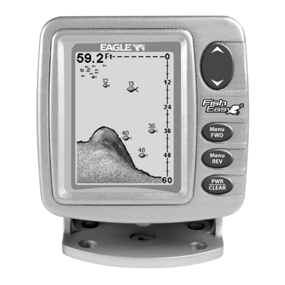
The unit sounds a tone when you press any key. This tells you the unit has accepted a command. Numbers in the photo correspond to key ex- planations below: Eagle FishEasy 2 Sonar, front view, showing screen and keyboard. 1. PWR/CLEAR (power and clear) This key appears in the manual text simply as turn the unit on and off. -
Page 32: Up And Down Arrows
. Use DOWN ARROW UP ARROW these keys to adjust virtually every feature and function on the sonar unit. MEMORY This unit has permanent memory that saves all user settings, even when power is removed. It does not require, nor does it use an internal backup battery, so you never have to worry about replacement batteries. -
Page 33: Chart Scroll (Stop Or Start Scroll)
If you don't want to wait, press the screen. When the sonar unit is first turned on and the backlight menu disap- pears, the display screen shows the Full Chart Page, or mode. The Fish I.D. feature is off. The depth range shows on the depth scale on the right side of the screen. -
Page 34: Screen Display Modes
The line at the top of the screen repre- sents the surface. The bottom depth (as determined by the digital sonar) shows in the upper left corner. -
Page 35: Split Chart
DUAL-FREQUENCY SPLIT CHART (SeaFinder 240DF only) This page shows sonar data from the 50 kHz transducer element on the left side of the screen and data from the 200 kHz transducer on the right side. All other functions and features are the same as the Full Chart page. -
Page 36: Large Digital (Lrg Digital)
NOTE: Temperature, speed, and distance require a temperature or speed sensor. These may be optional equipment, depending on the sonar model you purchased. until the MENU... -
Page 37: Range - Automatic And Manual
RANGE When turned on for the first time, the unit automatically adjusts the depth range according to water conditions. It always keeps the bottom displayed in the lower portion of the screen. You can over-ride the automatic range control and manually select a range. To do this, press until the menu appears. - Page 38 To zoom the display, first press the pears. Use the arrow keys to select either 2X or 4X zoom, then press to clear the menu. When the display is in Zoom mode, the screen will show a zoom indica- tor box at the top right corner of the screen. This is a reminder that the display is zoomed, and it tells what level of zoom is in effect.
-
Page 39: Sensitivity
When you Zoom in manual Range mode, echoes are enlarged near the middle of the displayed range. For example, with a manual depth Range of 100 feet, your screen shows the water column from zero at the top of the screen to 50 feet in the middle to 100 feet at the bottom of the screen. - Page 40 You can change the sensitivity level whether you are in Auto Sensitiv- ity mode or Manual Sensitivity mode. The adjustment method works the same in both modes, but it gives you slightly different results. Adjusting sensitivity in Auto Sensitivity Mode is similar to manually ad- justing a car's speed with the accelerator pedal while cruise control is on.
-
Page 41: Grayline
Since Grayline shows the difference between strong and weak signals, adjusting the sensitivity may also require a different Grayline level. The level chosen by the sonar unit at power on is usually adequate for most conditions. Experiment with your unit to find the Grayline setting that's best for you. -
Page 42: Fish I.d
At left, Grayline menu screen. Center, little Grayline indicates a soft bottom, probably sand or mud. At right, the wider Grayline indicates a FISH I.D. The Fish I.D. feature identifies targets that meet certain conditions as fish. The microcomputer analyses all echoes and eliminates surface clutter, thermoclines and other signals that are undesirable. -
Page 43: Fishtrack
Fish I.D. is an easier way for a sonar novice to recognize a fishy signal return when he sees it. However, locating fish by symbol only has some limitations. Your sonar unit's microcomputer is sophisticated, but it can be fooled. -
Page 44: Fishreveal Chart Mode
Fish ID menu and symbol with FishTrack on. The fish is 44 feet deep. FISHREVEAL When displaying actual sonar returns, the FishReveal feature helps show fish targets hidden by surface clutter, thermoclines, weed beds and other cover with 10 levels of gray tones. -
Page 45: Chart Scroll Speed And Hyperscroll
There are two FishReveal modes: standard and inverted. In standard mode, the weakest echoes are white and the strongest echoes are black. Echoes in between vary in gray in proportion to their signal strength. In Inverted FishReveal mode, the weakest echoes are black and the strongest echoes are white. -
Page 46: Noise Reject And Asp (Advanced Signal Processing)
40 percent. When you are stationary and a fish swims through the sonar signal cone, the image appears on the screen as a long line in- stead of a fish arch. Reducing the chart speed may result in a shorter line that more closely resembles a regular fish return. -
Page 47: Alarms
ASP is an effective tool in combating noise. In sonar terms, noise is any undesired signal. It is caused by electrical and mechanical sources such as bilge pumps, engine ignition systems and wiring, air bubbles passing over the face of the transducer, even vibration from the engine. In all cases, noise can produce unwanted marks on the display. -
Page 48: Shallow Alarm
To turn Fish I.D. on, press until the menu appears. Press MENU to select , then press UP ARROW To turn off the fish alarm without turning off fish symbols, press MENU until appears. Press to select , then DOWN DOWN ARROW LARM press... -
Page 49: Deep Alarm
Press to increase the shallow alarm's depth setting or press UP ARROW to decrease it. The number in the shallow alarm’s menu DOWN ARROW box shows the current shallow alarm setting. When the number reaches the desired setting, press depth goes shallower than the alarm’s setting, an alarm tone sounds and a message box appears on the screen. -
Page 50: System Setup
SYSTEM SETUP To customize the display, press until the MENU DOWN YSTEM ETUP menu appears, then press . The display contrast, units of UP ARROW measure, temperature, and system information screens are all under this menu. The Contrast menu appears first. Press the MENU UP keys to cycle through the menus. -
Page 51: Depth Units Of Measure
ous times of the day. The default setting is 50 percent. To adjust the contrast, press until the menu ap- MENU DOWN YSTEM pears, press , and the menu appears. To decrease UP ARROW ONTRAST screen contrast, press the key. Press the DOWN ARROW UP ARROW to increase screen contrast. -
Page 52: Temperature Units Of Measure
TEMPERATURE UNITS OF MEASURE This unit can show the temperature (if a temperature sensor is attached) in degrees Fahrenheit or Celsius. To change the unit of measure, press until the menu appears. Press , then MENU DOWN UP ARROW YSTEM press until the menu appears. -
Page 53: Reset Distance Log
RESET DISTANCE LOG You can reset the distance log to zero with this command. Press MENU until appears, then press . Press until DOWN UP ARROW MENU YSTEM menu appears. Press and the log returns to UP ARROW ESET zero. Press to clear the menu. -
Page 54: System Info (Operating Software Version)
SYSTEM INFO To show the operating software system information, press MENU DOWN until the menu appears, then press . Press UP ARROW MENU DOWN YSTEM until the screen appears. Press to clear the screen. YSTEM System Info screen. SIMULATOR This unit has a built-in simulator that shows a simulated bottom signal with fish signals. -
Page 55: Chart Setup
If you turn on your unit before attaching a transducer, it may enter a demo mode. The words "demo mode" flash on the bottom of the screen and a sonar chart plays much like the simulator. Unlike the simulator, the demo mode is for demonstration only, and will auto- matically stop as soon as you turn on the unit with a transducer at- tached. -
Page 56: Change Frequency (Seafinder 240Df Only)
This in turn can reduce the amount of detail seen on the sonar chart. Try this command only if you are in deep water, traveling at high speed, and notice a reduction in detail on the sonar chart. -
Page 57: Digital Data Size For Depth, Temperature, Speed And Distance Log
There is a common exception to these rules of thumb. Some fishermen on freshwater lakes (or the ocean) using downriggers like to see them on the sonar. In many of those cases, you'll see a 50 kHz transducer frequency in use because the wider cone angle lets them watch the bait. -
Page 58: Scales
Menus for changing digital number size. SCALES The depth scale between the upper and lower limit on the right side of the screen can be turned on or off. The default is on. Scales menu, with scale on (left) and off (right). With the scale off, only the upper and lower limits (zero and 60 in this case) are displayed To turn the scale off, press press... -
Page 59: Troubleshooting
Unit freezes, locks up, or operates erratically: 1. Electrical noise from the boat's motor, trolling motor, or an accessory may be interfering with the sonar unit. Rerouting the power and trans- ducer cables away from other electrical wiring on the boat may help. - Page 60 1. The transducer may be in turbulent water. It must be mounted in a smooth flow of water in order for the sonar to work at all boat speeds. Air bubbles in the water disrupt the sonar signals, interfering with its ability to find the bottom or other targets.
- Page 61 For example, turn on the bilge pump and view the sonar display for noise. If no noise is present, turn the pump off, then turn on the VHF radio and transmit.
- Page 62 Notes...
- Page 63 Notes...
- Page 64 Notes...
-
Page 65: Warranty And Service Information
FULL ONE-YEAR WARRANTY "We," "our," or "us" refers to EAGLE ELECTRONICS, a division of LEI, the manufacturer of this product. "You" or "your" refers to the first person who purchases this product as a consumer item for personal, family, or household use. -
Page 66: How To Obtain Service
8 a.m. to 5 p.m. Central Standard Time, M-F Eagle Electronics may find it necessary to change or end our shipping policies, regulations, and special offers at any time. We reserve the right to do so without notice. -
Page 67: Accessory Ordering Information For All Countries
1. Always use the original shipping container and filler material the product was packed in. 2. Always insure the parcel against damage or loss during shipment. Eagle does not assume responsibility for goods lost or damaged in transit. 3. For proper testing, include a brief note with the product describing the problem. -
Page 68: Visit Our Website
Eagle Pub. 988-0143-641 Printed in USA 092402 Visit our web site: www.eaglesonar.com © Copyright 2002 All Rights Reserved Eagle Electronics...
Need help?
Do you have a question about the FISHEASY 2T and is the answer not in the manual?
Questions and answers