
Related Manuals for Eagle FISHEASY 320C


Summary of Contents for Eagle FISHEASY 320C
- Page 1 Pub. 988-0143-781 www.eaglesonar.com Fish-Finding & Depth-Sounding Sonar Installation and Operation Instructions...
- Page 2 FishEasy 320C is a registered trademark of LEI Eagle Electronics may find it necessary to change or end our policies, regulations, and special offers at any time. We reserve the right to do so without notice. All features and specifications subject to change without notice.
-
Page 3: Table Of Contents
Introduction ... I Capabilities and Specifications: Fisheasy 320c ... 5 How Sonar Works ... 7 How to Use this Manual: Typographical Conventions... 8 Installation & Accessories... 11 Preparations... 11 Transducer Installation... 11 Recommended Tools and Supplies ... 12 Transom Installation ... 12 Trolling Motor Installations ... - Page 4 2. Ent/Pages (Enter and Pages)... 44 3. Exit ... 44 4. Up and Down Arrows... 44 Memory... 44 Menus ... 44 Main Menu ... 45 Sonar Menu ... 46 Pages ... 48 Basic Sonar Quick Reference ... 51 Sonar Operations ... 52 Fish Symbols vs.
- Page 5 Ping Speed & HyperScroll... 74 To Change Ping Speed: ... 75 To Adjust Sensitivity: ... 75 To Turn Off HyperScroll:... 75 Pop-Up Help ... 76 Reset Options ... 76 Reset Water Distance ... 77 Sensitivity & Auto Sensitivity... 77 Automatic Sensitivity ... 78 To Turn Auto Sensitivity Back On...
- Page 6 Notes...
-
Page 7: Introduction
320C has several powerful features you can control by scrolling through easy-to-use menus with the arrow and menu keys. To get started with your Eagle sonar, first read the installation section. It contains instructions for mounting the sonar unit, the transducer and any optional accessories, such as a speed sensor. - Page 8 Resolution:... 320 pixels (vert.) x 240 pixel (horiz.) resolu- Backlighting:... Backlit screen and keypad for night use. Input power:... 10 to 17 volts DC. Current drain: ... 200 ma lights off; 250 ma lights on. Back-up memory: ... Built-in memory stores sonar settings when Frequency:...
-
Page 9: How Sonar Works
Surface water temp: ... Yes, built into transducer. Optional addi- Speed/distance log: ... Yes, with optional speed sensor. NOTICE! The storage and operation temperature for your unit is from -4 de- grees to +167 degrees Fahrenheit (-20 degrees to +75 degrees Cel- sius). -
Page 10: How To Use This Manual: Typographical Conventions
chart. The sonar's microprocessor calculates the time lapse between the transmitted signal and echo return to determine the distance to the object. The whole process repeats itself several times each second. How to use this manual: typographical conventions Many instructions are listed as numbered steps. The keypad and arrow "keystrokes"... - Page 11 Instructions = Menu Sequences Most functions you perform with the sonar unit are described as a se- quence of key strokes and selecting menu commands. We've written them in a condensed manner for quick and easy reading. For example, instructions for turning on the Fish ID feature would look like this: 1.
- Page 12 Notes...
-
Page 13: Installation & Accessories
Installation & Accessories Preparations You can install the sonar system in some other order if you prefer, but we recommend this installation sequence: CAUTION: You should read over this entire installation section before drill- ing any holes in your vehicle or vessel! 1. -
Page 14: Recommended Tools And Supplies
vent damage if the transducer strikes an object while the boat is moving. If the transducer does "kick-up," the bracket can easily be pushed back into place without tools. Read these instructions carefully before attempting the installation. Determine which of the installation methods is right for your boat. Remember, the transducer location and installation is the most critical part of a sonar installation. -
Page 15: Selecting A Transducer Location
Selecting a Transducer Location 1. The location must be in the water at all times, at all operating speeds. 2. The transducer must be placed in a location that has a smooth flow of water at all times. If the transducer is not placed in a smooth flow of water, interference caused by bubbles and turbulence will show on the sonar's display in the form of random lines or dots whenever the boat is moving. -
Page 16: How Low Should You Go
be displayed on the sonar's screen. Use caution when routing the trans- ducer cable around these wires. CAUTION: Clamp the trans- ducer cable to transom near the transducer. This will help prevent the transducer from entering the boat if it is knocked off at high speed. -
Page 17: Shoot-Thru-Hull Vs. Transom Mounting
However, there are times when you may need to adjust the transducer slightly higher or lower. (The slots in the mounting brackets allow you to loosen the screws and slide the transducer up or down.) If you fre- quently lose bottom signal lock while running at high speed, the trans- ducer may be coming out of the water as you cross waves or wakes. -
Page 18: Transom Transducer Assembly And Mounting
Lack of angle adjustment can be particularly troublesome on hulls that sit with the bow high when at rest or at slow trolling speeds. Third, a transducer CAN NOT shoot through wood and metal hulls. Those hulls require either a transom mount or a thru-hull installation. Fourth, if your Skimmer transducer has a built in temp sensor, it will only show the temperature of the bilge, not the water surface temp. - Page 19 from the side, check to see if it will adjust so that its face is parallel to the ground. If it does, then the "A" position is correct for your hull. If the transducer's face isn't parallel with the ground, remove the transducer and ratchets from the bracket.
- Page 20 Assemble transducer and bracket. 4. Drilling mounting holes. Hold the transducer and bracket assembly against the transom. The transducer should be roughly parallel to the ground. The transducer's centerline should be in line with the bottom of the hull. Don't let the bracket extend below the hull! Mark the center of each slot for the mounting screw pilot holes.
- Page 21 5. Attaching transducer to transom. Remove the transducer from the bracket and re-assemble it with the cable passing through the bracket over the bolt as shown in the following figures. Route cable over bolt and through bracket. Side view shown at left and seen from above at right.
-
Page 22: Trolling Motor Bracket Installation
transducer. If possible, route the transducer cable away from other wir- ing on the boat. Electrical noise from the engine's wiring, bilge pumps, VHF radio wires and cables, and aerators can be picked up by the sonar. Use caution when routing the transducer cable around these wires. WARNING: Clamp the transducer cable to the transom close to the transducer. -
Page 23: Transducer Orientation And Fish Arches
TMB-S bracket Internal tooth washer Bolt Flat washer Attach motor mounting bracket to transducer. 2. Slide the adjustable strap supplied with the TMB-S through the slot in the transducer bracket and wrap it around the trolling motor. Posi- tion the transducer to aim straight down when the motor is in the wa- ter. - Page 24 Transducer aimed too far back Full fish arch Transducer angles and their effects on fish arches. If the arch slopes up – but not back down – then the front of the trans- ducer is too high and needs to be lowered. If only the back half of the arch is printed, then the nose of the transducer is angled too far down and needs to be raised.
-
Page 25: Shoot-Thru-Hull Preparation
Shoot-Thru-Hull Preparation Hulls With Floatation Materials The transducer installation inside a fiberglass hull must be in an area that does not have air bubbles in the resin or separated fiberglass lay- ers. The sonar signal must pass through solid fiberglass. A successful transducer installation can be made on hulls with flotation materials (such as plywood, balsa wood or foam) between layers of fiberglass if the material is removed from the chosen area. -
Page 26: Testing Determines Best Location
Testing Determines Best Location Ideally, the shoot-thru transducer should be installed as close to the transom as possible, close to the centerline. This will give you the best performance during high speed maneuvers. Transducer location Transducer location (trolling speed) (high speed) Shoot-thru-hull transducer locations for high speed or trolling speed operation. - Page 27 True bottom Second bottom Manual range setting Example of a second bottom signal. Unit is in 30 feet of water, with range set at 80 feet and sensitivity set at 87 percent. 2. Next, take the transducer out of the water and place it in the water in the sump of the boat, face down.
-
Page 28: Shoot-Thru-Hull Installation
with the boat on plane and observe the bottom signal. You'll need to figure some way to prop the transducer into position while you make your test run. (A brick or two might be sufficient to hold it in place.) 5. - Page 29 WARNING: Use only the epoxy available from LEI. It has been for- mulated to work with these installation procedures. Other epoxy types may be too thin or may not cure to the right consistency for optimum transducer performance. 2. The epoxy consists of the epoxy itself and a hardener. Remove the two compounds from the package and place them on the paper plate.
-
Page 30: Speed/Temperature Sensors
Speed/Temperature Sensors The FishEasy 320C can accept as many as two temperature sensors, which can be used to monitor the temperature of surface water, a live well or some other location. These units can accept an optional speed sensor for showing speed and distance traveled. However, you can only use one accessory at a time. - Page 31 Power/trans- ducer cable Sonar unit with external combination speed and temperature sensor. Primary temp sensor is built into the transducer. Sonar unit rear view ST-TU combination speed and temperature 12-volt battery Temperature sensor built into transducer sensor 3-amp fuse HST-WSU...
- Page 32 Power/trans- ducer cable Sonar unit with secondary external temperature sensor. Primary temp sensor is built into the transducer. Sonar unit rear view 12-volt battery Temperature sensor built into transducer TS-2U temperature sensor 3-amp fuse HST-WSU...
-
Page 33: Speed Sensor Installation
Power/trans- ducer cable Sonar unit with external speed sensor. The temperature sensor is built into the transducer. Speed Sensor Installation If you wish to purchase an optional sensor for your unit, refer to the accessory ordering information inside the back cover of this manual. The following instructions describe how to install the speed sensor. - Page 34 water flow to the speed sensor. Make sure the sensor will remain in the water when the boat is on plane. Also make sure the location doesn't inter- fere with the boat's trailer. Typically, the sensor is mounted about one foot to the side of the transom's centerline.
-
Page 35: Power Connections
If the base of the transom has a radius, fill the gap between the tran- som and the sensor with the caulking compound. This will help ensure a smooth water flow. Route the sensor's cable through or over the transom to the sonar unit. If you need to drill a hole in the transom to pass the connector through, the required hole size is 5/8". - Page 36 To unit Power and transducer connections for the FishEasy 320C sonar unit (direct battery connection shown). If possible, keep the power cable away from other boat wiring, espe- cially the engine's wires.
-
Page 37: Mounting The Sonar Unit: In-Dash, Bracket Or Portable
You can install the sonar unit on the top of a dash with the supplied bracket. At the time of this printing, we do not produce an in-dash mounting kit for the FishEasy 320C. If you wish to check on the future availability of this kit, refer to the accessory ordering information in- side the back cover of this manual. - Page 38 [3.03] Front view (left) and side view (right) showing dimensions of the FishEasy 320C when mounted on quick release bracket. After drilling the hole, pass the connectors up through the hole from under the dash. If you wish, you can fill in the hole around the cable with a good marine caulking compound.
- Page 39 Ratchet Screw hole Power/transducer cable FishEasy 320C quick release mounting bracket. Slots in the base allow routing the cable from beneath the mount. Attach the unit to the bracket by first connecting the power/transducer and accessory cables. Then, hold the sonar unit vertically and slide it onto the bracket from above.
-
Page 40: Portable Sonar Installation
Adjust viewing angle: use one hand to press and release the spring- loaded ratchets while you move the unit with the other hand. Portable Sonar Installation Like many Eagle products, the FishEasy 320C sonar is capable of port- able operation. It uses the optional PPP-12 portable power pack. Bracket front... -
Page 41: Installing The Batteries
The power pack and portable transducers expand the uses for your so- nar. You can use your FishEasy 320C sonar unit on your boat or take it to the dock, on a float tube, on an ice fishing trip or use it as a second sonar in a friend's boat. - Page 42 PPP-12 Portable Power Pack with FishEasy 320C stowed for transport. Turn the sonar unit on. If it doesn't work, make sure the battery termi- nals are making good contact against the battery contacts. Also check the wiring connections on the battery adapter. The red wire on the...
-
Page 43: Portable Transducer Assembly
Portable Transducer Assembly Recommended tools for installation include a slotted screw driver and two adjustable wrenches. Assemble the transducer and bracket as shown in the following figure. Attach the transducer to the bracket with the supplied hardware. Make sure there is one washer on each side of the transducer, inside the bracket. - Page 44 Moisten the cup, then press it onto the hull as firmly as possible. Tie the nylon cord to the boat and route the transducer cable to the sonar unit. Your portable sonar is now ready for use. Hull Portable transducer installed on boat transom. NOTE: For optimum operation, the portable transducer should be adjusted so that it is parallel to the ground.
-
Page 45: Basic Sonar Operation
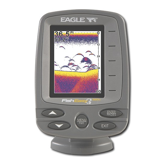
The unit sounds a tone when you press any key. This tells you the unit has accepted a command. Numbers in the photo correspond to key ex- planations below: FishEasy 320C Sonar, front view, showing screen and keyboard. 1. MENU/PWR (menu and power) This key appears in the manual text simply as . -
Page 46: Ent/Pages (Enter And
the unit's operation. Press twice to access the Main Menu. NOTE: You must hold the to turn the unit off. 2. ENT/PAGES (enter and pages) This key appears in the manual text simply as menu or adjusting a feature, use this key to select a highlighted option. When no menus are on the screen, pressing this key will make the unit cycle through the four Sonar Chart Display Options. -
Page 47: Main Menu
Main Menu The Main Menu contains some basic function commands and some setup option commands. You access the Main Menu by pressing MENU MENU You run a command by using ↑ or ↓ to highlight the command and then pressing . -
Page 48: Sonar Menu
use. It tells you when the sonar sees a fish. You can also set deep or shallow depth alarms. • Popup Help command: turns the pop-up help boxes on or off. When you select a menu command, these information boxes appear to tell you what the command does or how to use the command. - Page 49 Sonar Page Menu. Most of these functions are discussed in the Ad- vanced Section. Sonar Menu Commands The Sonar Menu contains commands for the major sonar features and options. Most of them are described in detail only in the Advanced Sec- tion, but Sensitivity and Auto Sensitivity are important basic functions that are discussed both here and in the Advanced Section.
- Page 50 • Zoom Level command: controls the display size of sonar signal im- ages. Pages The FishEasy 320C has three major display options. They are the Full Sonar Chart, Split Zoom Sonar Chart, and Digital Data. You access the various display modes by pressing the key.
- Page 51 Digital data overlay (depth & temperature) Fish arches around school of bait fish Structure Bottom signal Sonar Page, showing full sonar chart mode. Sonar chart display options: full sonar chart (left) and split zoom. Surface signal Surface clutter Depth scale Zoom bar In FasTrack, fish arches show as...
- Page 52 Sonar chart display options: digital data. You can customize how the Sonar Page pictures and other data are dis- played in many ways. We'll discuss all of those features and options in the Advanced Section, but to show you how easy the sonar unit is to op- erate, the next two pages contain a simplified, 10-step quick reference that will cover most fish finding situations.
-
Page 53: Basic Sonar Quick Reference
Basic Sonar Quick Reference 1. Mount the transducer and unit. Connect the unit to electric power and the transducer. 2. Launch your boat. 3. To turn on the unit, press and release 4. Head for your fishing grounds. Your unit automatically displays digi- tal depth and surface water temperature in the corner of the screen. -
Page 54: Sonar Operations
8. Gauge the fish depth by visually comparing the fish arches with the depth scale on the right side of the screen, or get a more accurate measure with the Depth Cursor. Press |↓ to MENU EPTH URSOR Press ↓ (or ↑) to align the cursor line with the fish arch. The exact depth appears in a box at the right end of the cursor line. - Page 55 Bait Thermocline with fish Fish arches Fig. 1 Fig. 3 These figures show results of different sensitivity levels on the same location. Fig. 1: Sensitivity at 87 percent, determined by Auto Sensitiv- ity. Typical of full auto mode. Fig. 2: Sensitivity set at 50 percent. Fig. 3: Sensitivity set at 20 percent.
- Page 56 You can change the sensitivity level whether you are in Auto Sensitiv- ity mode or Manual Sensitivity mode. The adjustment method works the same in both modes, but it gives you slightly different results. Adjusting sensitivity in Auto Sensitivity Mode is similar to manually ad- justing a car's speed with the accelerator pedal while cruise control is on.
-
Page 57: Fish Symbols Vs. Full Sonar Chart
Display showing Sensitivity Control Bar. NOTE: If you want to change the sensitivity in Manual Mode, first turn off Auto Sensitivity: from the Sonar Page, press |↑ to ENSITIVITY sensitivity setting. When it's set at the desired level, press Important Tip: While you are experimenting and learning, it's possible to scramble the settings so that the sonar picture disappears from your screen. -
Page 58: Other Free Training Aids
Aside from being just plain fun, this program can help you learn both basic and advanced operations without burning boat fuel! Eagle is one of the first sonar manufacturers to provide this type of training tool for customers. - Page 59 This PC application simulates the actual sonar unit on your computer. You can run it from your computer keyboard or use your mouse to press the virtual keys. Easy download and installation instructions are avail- able on our web site. Free training emulator is available for your unit on our web site.
-
Page 60: Advanced Sonar Options & Other Features
Advanced Sonar Options & Other Features Material in this section is arranged in alphabetical order. ASP (Advanced Signal Processing) The ASP feature is a noise rejection system built into the sonar unit that constantly evaluates the effects of boat speed, water conditions and interference. -
Page 61: Alarms
In the Sonar Features menu, Noise Rejection is selected with ASP in the default low setting. To change the ASP level: 1. From the Sonar Page, press 2. Press ↓ to OISE 3. Press ↓ or ↑ to select a setting, then press 4. -
Page 62: To Adjust And Turn On The Shallow Alarm
The deep alarm works just the opposite. It sounds a warning tone if the bottom depth goes deeper than the alarm's setting. Both depth alarms work only off the digital bottom depth signals. No other targets will trip these alarms. These alarms can be used at the same time or individually. At left, Main Menu and Sonar Alarms command. -
Page 63: Fish Alarm
5. To turn off the alarm, press LARM NABLED To switch to a different depth setting, open the Sonar Alarms menu and repeat the instructions in step 3 above. Fish Alarm Use the fish alarm for a distinctive audible alarm when fish or other suspended objects are detected by the Fish I.D.... -
Page 64: Calibrate Speed
Press |↓ to . The slider MENU MENU ACKLIGHT EVEL ACKLIGHT EVEL bar appears. Press ↑ or ↓ to move the bar. At The lower end of the scale backlighting is turned off; the upper end is maximum backlight level. Backlight Level Command, left, and Backlight Level control bar, right. -
Page 65: Chart Speed
Chart Speed The rate that echoes scroll across the screen is called the chart speed. The default is maximum; we recommend that you leave the speed set there for virtually all fishing conditions. However, you might consider experimenting with chart speed when you are stationary or drifting very slowly. -
Page 66: Colorline
3. When it's set at the desired level, press EXIT ColorLine ColorLine lets you distinguish between strong and weak echoes. It "paints" a brighter color on targets that are stronger than a preset value. This allows you to tell the difference between a hard and soft bottom. -
Page 67: Contrast
2. The ColorLine Control Bar appears. Press ↓ to decrease ColorLine; press ↑ to increase ColorLine. 3. When it's set at the desired level, press Thin or no ColorLine At left, little ColorLine indicates a soft bottom, probably sand or mud. At right, the wider ColorLine indicates a harder, rocky bottom. -
Page 68: Depth Cursor
Contrast Command, left, and Contrast control bar, right. Depth Cursor The depth cursor consists of a horizontal line with a digital depth box on the right side. The numbers inside the box show the depth of the cursor. Cursor line Depth box Sonar chart with the depth cursor active. -
Page 69: Depth Range - Automatic
1. From the Sonar Page, press 2. The depth cursor appears. Press ↓ to lower the cursor line; press ↑ to raise the cursor line. 3. To clear the depth cursor, press Depth Range - Automatic When turned on for the first time, the bottom signal is automatically placed in the lower half of the screen. -
Page 70: To Turn Auto Depth Range On Again
To switch to Manual Depth Range: 1. First, turn off automatic depth range. From the Sonar Page, press |↓ to MENU EPTH 2. Press ↑ to EPTH 3. Press ↓ or ↑ to select a different depth range. A horizontal blue bar highlights the selected range. -
Page 71: Fish I.d. (Fish Symbols & Depths)
Fish arches Structure Bottom signal ColorLine Fish I.D. (Fish Symbols & Depths) The Fish I.D. feature identifies targets that meet certain conditions as fish. The microcomputer analyzes all echoes and eliminates surface clutter, thermoclines, and other signals that are undesirable. In most instances, remaining targets are fish. -
Page 72: Fishtrack
Does that mean Fish I.D. is broken? No — the feature is simply inter- preting sonar returns in a specific way to help take some of the work out of reading the screen. Remember: Fish I.D. is one of the many tools we provide so you can analyze your sonar returns for maximum fish finding information. -
Page 73: Overlay Data
To turn on FishTrack: (Note: These instructions will turn on FishTrack and Fish I.D. at the same time.) 1. From the Sonar Page, press 2. Press ↓ to ID D To turn off FishTrack, repeat these instructions. Turning off FishTrack in this manner will not turn off Fish I.D. - Page 74 Overlay Data Shown selection menu. In this example, we scrolled down the data list to highlight "Water Speed." When selected, a check mark appears beside the data type. (If you wish, you may now use ↓ or ↑ to select other Data Types for display.) Data list showing "Water Speed"...
-
Page 75: To Change Displayed Data Font Size
3. To return to the previous page, press To change displayed data font size: 1. Press |↓ to MENU 2. Press ↓ or ↑ to select Data Type, then press played in the bottom of the Overlay Data Shown window) cycles through available sizes. -
Page 76: Ping Speed & Hyperscroll
Sonar chart with Overlay Data turned on. This example shows Depth, Water Temperature and the Water Speed of the boat. Ping Speed & HyperScroll Ping Speed controls the rate at which the transmitter and transducer broadcast sonar sound waves — pings — into the water. The unit has a default ping speed of 50 percent. -
Page 77: To Change Ping Speed
decrease the sensitivity to a level that eliminates the clutter. When you turn HyperScroll off, you can return to your original sensitivity level. Ping Speed Control Bar at default setting. To change Ping Speed: 1. From the Sonar Page, press 2. -
Page 78: Pop-Up Help
returns, just as you would on a flasher sonar unit. For more informa- tion on FasTrack, see its entry in this section. Pop-up Help Help is available for virtually all of the menu labels on this unit. By highlighting a menu item and leaving it highlighted for a few seconds, a "pop-up"... -
Page 79: Reset Water Distance
3. All the menus are cleared and all options are returned to the factory settings. At left, Main Menu with Reset Options command selected. On the right, Yes is selected for Reset all the options? Reset Water Distance The sonar chart's Digital Data display option includes a window that shows distance traveled, called Water Distance ("W Distance"). -
Page 80: Automatic Sensitivity
High sensitivity levels let you see this detail, but it can also clutter the screen with many undesired signals. Typically, the best sensitivity level shows a good solid bottom signal with ColorLine and some surface clut- ter. Automatic Sensitivity The default sensitivity mode is automatic. The unit bases the sensitiv- ity level on water depth and conditions. -
Page 81: To Turn Auto Sensitivity Back On
To adjust sensitivity in manual mode: 1. First, turn off Auto Sensitivity: from the Sonar Page, press ENSITIVITY 2. Press ↑ to ENSITIVITY Press ↓ or ↑ to pick a different sensitivity setting. When it's set at the desired level, press To turn Auto Sensitivity back on: From the Sonar Page, press NOTE:... -
Page 82: Set Keel Offset
Set Keel Offset This unit measures water depth from the face of the transducer. Since the transducer is installed below the water surface, the distance dis- played by the digital depth, chart depth scale, chart cursor or fish sym- bols is not the exact water depth. If the transducer is 1 foot below the surface, and the screen shows the water depth as 30 feet, then the ac- tual depth is 31 feet. -
Page 83: Set Language
Software Version Information From time to time, Eagle updates the operating system software in some of its products. These software upgrades are usually offered to customers as free downloads from our web site, www.eaglesonar.com. -
Page 84: Sonar Chart Mode
3. Press ↓ or ↑ to Mode Name| 4. Press EXIT EXIT Sonar Page & Sonar Chart Display Options The FishEasy 320C offers three chart display options. To cycle through them, press to clear any menus, then press EXIT the desired mode appears. -
Page 85: Full Sonar Chart
Full Sonar Chart This is the default mode used when the unit is turned on for the first time or when it's reset to the factory defaults. The bottom signal scrolls across the screen from right to left. Depth scales on the right side of the screen aid in determining the depth of targets. -
Page 86: Digital Data/Chart
Split Zoom Sonar Chart. Image at left shows the left window zoomed to 2X. The right image shows the left window zoomed to 4X. The depth overlay data is set to the default large text size; the water temperature is set to the medium text size. Digital Data/Chart This mode shows five large digital boxes or windows containing: Water Depth;... -
Page 87: Sonar Simulator
Sonar Simulator This unit has a built-in simulator that lets you run it as if you were on the water. All sonar features and functions are useable. When in simulator mode, you will occasionally see the word Simulated in the Sonar Page at the bottom of the screen. -
Page 88: Surface Clarity
Sonar Menu with Stop Chart command selected. The box is unchecked, indicating that the chart is scrolling across the screen. Surface Clarity The markings extending downward from the zero line on the chart are called "surface clutter." These markings are caused by wave action, boat wakes, temperature inversion and more. -
Page 89: Transparency
Sonar Features menu with Surface Clarity selected. 2. Press ↓ or ↑ to select clarity level| EXIT EXIT EXIT Surface clutter In the illustration at left, Surface Clarity is turned off. The right view shows Surface Clarity set at High. Transparency Use the transparency menu to adjust the transparency of menu win- dows. -
Page 90: Units Of Measure
may fade until it is unreadable. A low transparency will usually make menu text easier to read, at the cost of watching your sonar returns. Experiment with this feature until you find the right level of transpar- ency for your eyes. Main Menu with Transparency command selected. -
Page 91: Zoom & Zoom Bar
Main Menu, left, Units of Measure Menu, right. To set Units of Measure: Press ↓ to the desired units, then press ENT. After all the options are set as desired, press to return to the EXIT EXIT page display. Volume This command adjusts the speaker volume, which controls the sound levels for keystrokes and alarms. - Page 92 For example, turning on the 2X zoom will show all echoes that are be- tween the top and bottom of the 2X zoom bar. The 4X zoom will show only the echoes between the top and bottom of the 4X zoom bar. At left, Sonar Page, normal view.
-
Page 93: Zoom Pan
Illustration at left shows Zoom Bar and 2X zoom level, at right, 4X. Tip: From the Sonar Menu, you can go directly to the Zoom Level com- mand with one keystroke. Instead of pressing the down arrow (↓) to reach the command, press the up arrow (↑) instead. This will take you from "Sensitivity"... - Page 94 Notes...
-
Page 95: Troubleshooting
Troubleshooting If your unit is not working, or if you need technical help, please use the following troubleshooting section before contacting the factory customer service department. It may save you the trouble of returning your unit for repair. For contact information, refer to the last page, just inside the back cover of this manual. - Page 96 Weak bottom echo, digital readings erratic, or no fish signals: 1. Make sure the transducer is pointing straight down. Clean the face of the transducer. Oil, dirt and fuel can cause a film to form on the trans- ducer, reducing its effectiveness. If the transducer is mounted inside the hull, be sure it is shooting through only one layer of fiberglass and that it is securely bonded to the hull.
-
Page 97: Noise
signals such as fish or even structure from the display. Try using resis- tor spark plugs or routing the sonar unit's power and transducer cables away from other electrical wiring on the boat. No fish arches when the Fish I.D. feature is off: 1. - Page 98 present, turn the pump off, then turn on the VHF radio and transmit. Keep doing this until all electrical equipment has been turned on, their effect on the sonar display noted, then turned off. If you find noise interference from an electrical instrument, trolling mo- tor, pump, or radio, try to isolate the problem.
- Page 99 Accessories, 5, 11, 35, 36 Alarms, 45, 59, 60, 61 Depth Alarms, 59 Fish Alarm, 59, 61 Antenna, 96 ASP (Advanced Signal Processing), 24, 58 Backlights / Lighting, 6, 45, 61, 62, 77 Batteries, 11, 33, 34, 39, 40, 44, 93, 94, Calibrate Speed, 62 Chart Speed, 47, 63 Contrast, 45, 65, 66, 77...
- Page 100 Digital Data, 48, 77, 84 Ping Speed, 48, 71, 74, 75 HyperScroll, 71, 74 Pop-up Help, 76 Power, 6, 8, 11, 33, 34, 35, 37, 38, 39, 40, 43, 44, 51, 78, 93, 94, 95, 96 Product Specifications, 5 Range, 24, 25, 47, 67, 68, 83, 91, 94, 95 Automatic, 67 Manual, 67 Reset Options, 46, 55, 76, 77, 79...
- Page 101 EAGLE ELECTRONICS FULL ONE-YEAR WARRANTY "We," "our," or "us" refers to EAGLE ELECTRONICS, a division of LEI, the manufacturer of this product. "You" or "your" refers to the first person who purchases this product as a consumer item for personal, family, or household use.
-
Page 102: How To Obtain Service
8 a.m. to 5 p.m. Central Standard Time, M-F Eagle Electronics may find it necessary to change or end our shipping policies, regulations, and special offers at any time. We reserve the right to do so without notice. -
Page 103: Accessory Ordering Information For All Countries
1) Your local marine dealer or consumer electronics store. Most quality dealers that handle marine electronic equipment or other consumer electronics should be able to assist you with these items. To locate an Eagle dealer near you, visit our web site, and look www.eaglesonar.com for the Dealer Locator. -
Page 104: Visit Our Website
Visit our web site: www.eaglesonar.com Eagle Pub. 988-0143-781 Copyright © 2004 All Rights Reserved LEI-Eagle Printed in USA 092304...
Need help?
Do you have a question about the FISHEASY 320C and is the answer not in the manual?
Questions and answers