Table of Contents
Advertisement
Quick Links
■ This product is eligible for the P2HD 5 Year
Warranty Repair Program. For details,
see page 12.
DEUTSCH
Für Erlauterungen in Deutsch, konsultieren Sie bitte die mitgelieferte CD-ROM.
FRANÇAIS
Pour des explications en français, veuillez vous reporter au CD-ROM fourni.
ITALIANO
Per le istruzioni in italiano, vedere il CD-ROM in dotazione.
ESPAÑOL
Para la explicación en español, consulte el CD-ROM uministrado.
Before operating this product, please read the instructions carefully and save this manual for future use.
• AVC-Intra capability is available when the optional AVC-Intra Codec board AJ-YBX200G is installed to the unit.
S1207T0 -P
D
Printed in Japan
Memory Card Portable Recorder/Player
Operating Instructions
AJ-HPM110P
Model No.
AJ-HPM110E
Model No.
ENGLISH
VQT1Q19
Advertisement
Table of Contents

Subscribe to Our Youtube Channel
Related Manuals for Panasonic AJHPM110E - MEMORY CARD PORTABLE RECORDER/PLAYER


Summary of Contents for Panasonic AJHPM110E - MEMORY CARD PORTABLE RECORDER/PLAYER
- Page 1 ■ This product is eligible for the P2HD 5 Year Operating Instructions Warranty Repair Program. For details, see page 12. Memory Card Portable Recorder/Player AJ-HPM110P Model No. AJ-HPM110E Model No. DEUTSCH Für Erlauterungen in Deutsch, konsultieren Sie bitte die mitgelieferte CD-ROM. FRANÇAIS Pour des explications en français, veuillez vous reporter au CD-ROM fourni.
-
Page 2: Read This First
FROM ALL LIQUIDS. USE AND STORE ONLY require the use of a different AC plug. Please IN LOCATIONS WHICH ARE NOT EXPOSED TO contact either a local or foreign Panasonic THE RISK OF DRIPPING OR SPLASHING authorized service center for assistance in LIQUIDS, AND DO NOT PLACE ANY LIQUID selecting an alternate AC plug. -
Page 3: Important Safety Instructions
Read this first! (continued) For AJ-HPM110P IMPORTANT SAFETY INSTRUCTIONS 1) Read these instructions. 2) Keep these instructions. 3) Heed all warnings. 4) Follow all instructions. 5) Do not use this apparatus near water. 6) Clean only with dry cloth. 7) Do not block any ventilation openings. Install in accordance with the manufacturer’s instructions. 8) Do not install near any heat sources such as radiators, heat registers, stoves, or other apparatus (including amplifiers) that produce heat. - Page 4 Responsible Party: Panasonic Corporation of North America One Panasonic Way, Secaucus, NJ07094 Support contact: Panasonic Broadcast & Television Systems Company 1-800-524-1448 This device complies with Part 15 of FCC Rules. Operation is subject to the following two conditions: (1)This device may not cause harmful interference, and (2) this device must accept any interference received, including interference that may cause undesired operation.
- Page 5 If you lose the fuse cover the plug must not be used until a Fuse replacement cover is obtained. A replacement fuse cover can be purchased from your local Panasonic Dealer. indicates safety information.
- Page 6 Read this first! (continued) For AJ-HPM110E ■ THIS EQUIPMENT MUST BE EARTHED CAUTION: To ensure safe operation, the three-pin plug must be TO REDUCE THE RISK OF FIRE OR SHOCK inserted only into a standard three-pin power point which is HAZARD AND ANNOYING INTERFERENCE, effectively earthed through normal household wiring.
-
Page 7: Table Of Contents
Contents Accessories ....................12 Included Accessories ................. 12 Optional Accessories .................. 12 Opening and Closing the Top Panel ............13 Introduction Features .....................14 Control Reference Guide ................17 Audio and Video Controller ................. 17 GUI Operations ................... 21 Panel Control Unit and Card Slots .............. 24 LCD Panel .................... - Page 8 Attaching Shot Marks .................. 51 Copying Clips .................... 52 Deleting Clips .................... 53 Repairing and Reconnecting Clips ............54 Repairing Bad Clips ..................54 Reconnecting Incomplete Clips ..............54 Viewing and Revising Clip Information ............. 55 Viewing Clip Information ................55 Revising Clip Metadata ................
- Page 9 Audio Split Editing ..................91 Registering From Video ................92 Adding and Registering Audio Split Point (Changing Registered Point) ..93 Trimming the Audio Split Point ..............93 Cancelling an Audio Split Setting ..............94 Simplified Voice-Over ................95 Preparing for Voice-Over ................95 Voice-Over From Still Image Status ............
- Page 10 OPERATION ....................125 INTERFACE ....................127 TIME CODE ....................128 VIDEO ......................130 AUDIO ....................... 135 DIF ......................138 MENU ......................139 Saving Menu Settings to SD Memory Cards ..........140 Time Code, User Bit and CTL ..............142 Superimpose Screen ................146 List of Compatible Input and Output Formats .........
- Page 11 ■ Panasonic makes no guarantees for your recordings Please understand that Panasonic makes no guarantees for your recordings in cases where images and/or sound were not re- corded as you intended due to problems with this unit or P2 cards.
-
Page 12: Accessories
Details about user registration and the extended warranty: Please note, this is a site that is not maintained by Panasonic Canada Inc. The Panasonic Canada Inc. privacy policy does not apply and is not applicable in relation to any information submitted. This link is provided to you for convenience. -
Page 13: Opening And Closing The Top Panel
Opening and Closing the Top Panel ◆NOTE Closing the Top Panel • Take care to avoid pinching your fingers when opening and closing the top panel. Make sure the EJECT button is folded downwards. • Check that the card lock is set to on before closing the top If not folded, fold the EJECT button to the right and set the panel. -
Page 14: Introduction
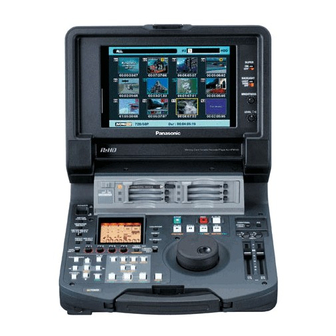
Introduction Features The AJ-HPM110 is a portable memory card recorder/player equipped with six P2 card (*) slots and a 9-inch color LCD monitor. Capability to record and play back audio and video in the compressed DVCPRO HD, DVCPRO50, DVCPRO/DV and AVC-Intra (option) formats on six P2 cards (*) allows you to use the unit like a conventional editing VTR player. - Page 15 PC card slot in this unit for immediate access. The P2 (Native), the unit is also capable of playing back cards card is a semiconductor memory card that Panasonic recorded at 24 fps and converting the output to 1080/24 PsF.
- Page 16 ■ Dial Jog/Dial Shuttle ■ Support for 59.94 Hz, 50 Hz, 23.98 Hz, 24 Hz and 25 Hz HD/SD The jog provides slow playback at rates between -1.0 to This unit can record and play back 59.94 Hz, 50 Hz, 23.98 Hz, +1.0.
-
Page 17: Control Reference Guide
Control Reference Guide Audio and Video Controller CONTROL REMOTE LOCAL UNITY UNITY Headphones connector POWER switch AUDIO MONITOR SELECT button Turns the power on and off. Switches the audio signals to be output to the MONITOR L/R connectors and the headphones jack. Each press of the METER (FULL/FINE) selector button button switches the output signals to the MONITOR L/R Switches the scale of the audio level meter. - Page 18 METER SELECT switch Audio playback level controls Switches to CH1-4 or CH5-8 in the audio meter and the Adjust the playback level of audio signals (of channels monitor. selected using the UNITY/VAR channel select switch). However, they cannot adjust the playback level of 1394 output signals.
- Page 19 ➝For details, refer to “Simplified Voice-Over” (page TCG switch 95), and “Copying Event Audio to EXTRA track” INT REGEN: The internal time code generator (page 87). synchronizes with the time code read by the time code reader from REC button the P2 card.
- Page 20 TEXT MEMO/MARKER button TEXT MEMO: Press this button during recording and playback where you wish to enter a text memo. In the thumbnail screen, press this button to add a text memo at the start of a clip. ➝For details, refer to “Attaching Text Memos”...
-
Page 21: Gui Operations
GUI Operations 14 13 12 CONTROL REMOTE LOCAL UNITY UNITY 7 8 9 10 11 PLAY LIST button EXIT/CANCEL/PF button Press to create play lists or to play a created play list. When the PLAY LIST/ Press to return to the The PLAY LIST button lights and the play list screen THUMBNAIL buttons thumbnail display from... - Page 22 MENU/DIAG button TRIM–/SLOT SELECT– button MENU button Hold down the IN, OUT or SPLIT button and press this Press this button to open the MENU. Press again to button in play list mode to shift the IN, OUT and SPLIT return to the previous screen.
- Page 23 • Press this button after the PF button when the Use the EVENT button to enable control of an external THUMBNAIL and PLAY LIST buttons are off to obtain device connected to the unit via the RS-422A or access to the setup menu registered using the PF3 IEEE1394 interface when the THUMBNAIL and PLAY button.
-
Page 24: Panel Control Unit And Card Slots
Panel Control Unit and Card Slots OFF ON CARD LOCK 9-inch Color LCD Monitor Stereo speakers Thumbnail screens facilitate video searches and Outputs the audio monitor sound. checks. LEVEL control Card Lock Adjusts the sound volume of the internal speaker and This lever locks the cards in place when the top panel headphones. -
Page 25: Lcd Panel
LCD Panel VIDEO AUDIO CMPST ANALOG 1394SG 1394SG SYSTEM 59.9450 1080i720p AVC-I DVCPRO Level meter TV system display Indicates the level of audio signals for CH1, CH2, CH3 Indicates the selected TV system. Use the SYSTEM and CH4. setting in setup menu No. 25 SYSTEM FREQ to switch The input signal level of audio signals is indicated between 59.94 Hz, 50 Hz or other settings. -
Page 26: Rear Panel
Rear Panel SERIAL DIGITAL COMPONENT AUDIO and VIDEO ANALOG AUDIO IN connectors/impedance IN/OUT connectors switches/CH2 input switches These connectors enable input and output of serial Analog audio input connectors digital component audio and video signals. The input impedance of CH1-2 to CH3-4 can be switched. - Page 27 DC IN socket Remote control connector Connect a 12 V DC power supply here. Use an external This unit can be connected to an external controller to 12 V DC, 4.8 A (15 A peak or more) DC power supply. enable remote operation of the unit.
- Page 28 • When no cable is connected to REF VIDEO OUT connector, • AV signals may be disrupted when connected devices are the REF VIDEO IN connector is automatically terminated at turned on and off or when the interface cable is connected 75 Ω.
- Page 29 (This way) IEEE1394 IEEE1394 connector cable plug (Not this way) IEEE1394 IEEE1394 connector cable plug • When connecting this unit to an external device, first connect the IEEE1394 cable to the external unit and then to this unit. Connecting the cable to this unit first may damage it by the static electricity generated.
-
Page 30: Side Panel
• For the latest information not available in the Operating Instructions, visit the P2 support desk at the following Web sites. For English: https://eww.pavc.panasonic.co.jp/pro-av/ • The term “SD memory card” will be used below as a generic for SD and SDHC memory cards. -
Page 31: Moving Between Screens And Menu Operations
Moving Between Screens and Menu Operations Operating Modes This unit provide the three operating modes described below. Recording and Displays video and performs Use the THUMBNAIL and PLAY LIST buttons to select these playback modes recording or playback. modes. Lamps indicate which mode is currently engaged. Thumbnail mode Shows thumbnails of clips and manages clips. -
Page 32: Menu Operations
Menu Operations Press the MENU button in each mode to open the menu. Press the MENU button to open the menu. Perform menu operations as described below. Use the cursor buttons to place the cursor on menu items. ◆ NOTE: •... -
Page 33: Using The On-Screen Keyboard
Using the On-screen Keyboard Using the Full Keyboard Using the Ten Keypad The full keyboard appears when necessary. The ten keypad appears when necessary. Move the cursor to the character you want to enter and press Move the cursor to the character you want to enter and press the SET button. -
Page 34: Recording, Playback And P2 Card Handling
Recording, Playback and P2 Card Handling Insert a P2 Card Bend the protruding EJECT button downwards to the ◆ NOTE: right and set the card lock to ON. • When you use this unit for the first time, be sure to set the internal clock in setup menu No. -
Page 35: Loop Rec Function
◆ NOTE: P2 Card Access LEDs and P2 Card Status • Detailed check of P2 card status is possible. Refer to “Checking Card Status” on page 64. P2 card access LED P2 card status Green light Reading and writing are possible. Dividing clips over 4 GB in length Orange light Reading and writing are possible. -
Page 36: Removing P2 Cards
• When LOOP REC MODE is set to ON, P2 card remaining free space ◆ NOTE: indicates the minimum guaranteed recording time. Minimum • Turning the POWER switch OFF turns off the LOOP REC function guaranteed recording time is the estimated time of a recording in a and it will remain off when the unit is powered up next time. -
Page 37: Preventing Accidental Deletion
SD memory cards For the latest information not available in the Operating Instructions of P2 cards and SD memory cards, visit the P2 support desk at the following Web sites. For English: https://eww.pavc.panasonic.co.jp/pro-av/ Introduction: Recording, Playback and P2 Card Handling... -
Page 38: Connections
Connections • In 23.98 Hz mode, the composite monitor video signal output by the Example of connections in 23.98/24/ ANALOG COMPOSITE MONITOR OUT connector does not include VITC signals. 29.97/25 Hz mode • For details on compatible input and output formats, refer to “List of Compatible Input and Output Formats”... -
Page 39: Recording From A Variable Frame-Rate Camera
Recording From a Variable Frame-Rate Camera Recording HD SDI output signals from a variable frame-rate camera as 720/ 23.98p Combined with a variable frame-rate camera (VariCam: AJ- Make the following setup menu settings. HDC27 series), the unit makes it possible to record HD SDI (720/ Item Setting 23.98p over 59.94p) output from the camera as DVCPRO HD or... -
Page 40: Recording Hd Sdi Signals Output By An Hd Camera As 1080/23.98P (Requires Optional Accessories)
◆ NOTE: Variable Frame Rate-Recording • Audio and external time codes cannot be recorded in this mode. • In this mode, the remaining P2 card capacity at 60p (50p), the To record active frames from the output of a variable frame- slowest slow-speed effect, is indicated. -
Page 41: Jog And Shuttle Operations Using The Search Dial
Jog and Shuttle Operations Using the Search Dial The search dial is used to search and check video. When the power is turned on, the search dial will not operate Each press of the dial alternates it between SHTL mode and unless it is first returned to the STILL position. -
Page 42: Clip Management
Clip Management Thumbnail and Clip Management 15 14 9 10 11 12 13 This unit provides a thumbnail screen for managing clips. A clip is a single data item that contains video, audio, metadata and other additional information. Normally, a clip is one shot generated from the start of recording until recording stops. -
Page 43: Thumbnail Screen Names And Functions
Thumbnail Screen Names and Functions Display status Thumbnail Display status indicates the type of thumbnails Indicates the initial frame of the clip that represents it. displayed on the screen. ALL: All clips Clip no. SAME FORMAT: Clips with the same format Indicates the numbers assigned to P2 card clips. - Page 44 Instead of appears to indicate that a clip is not in the P2 standard format. P2 card slot number and hard disk drive status 2 3 4 5 6 P2 card and USB hard disk drive status is indicated as described below.
-
Page 45: Changing Thumbnail Display
Changing Thumbnail Display The thumbnail screen can be customized to suit operating Use the cursor buttons to select the clip type that conditions and improve efficiency. should appear under [THUMBNAIL]. Switching the Type of Information That is Displayed ALL CLIP: Show all clips SAME FORMAT Show clips in the same format as... - Page 46 TEXT MEMO IND.: Shows the text memo Setting Items to Display indicator Hides the text memo The thumbnail display can be customized to suit different indicator operating needs. The following describes procedures for changing thumbnail display indicators and data settings. WIDE IND.: Shows the wide indicator Hides the wide indicator...
-
Page 47: Thumbnail Editing
Press the SET button. • Playback starts from the beginning of the clip regardless of a change in thumbnail location. ◆ NOTE: • Selecting [THUMBNAIL INIT] opens a confirmation screen. Select [YES]. Press the MENU button to end processing. Thumbnail editing Attach a text memo to video you want to edit. -
Page 48: Selecting Clips
Selecting Clips Select clips for processing in the thumbnail screen as Canceling a Selection described below. Place the cursor on a selected clip and press the SET button again. This cancels the selection. ◆ NOTE: • Holding down the SHIFT button while pressing the EXIT button cancels made selections. -
Page 49: Playing Back Clips
Playing Back Clips Press the PLAY button Playback starts from the clip the cursor is on. After the clip at the cursor location has been played, subsequent clips are played back in order. When the last CONTROL REMOTE LOCAL clip has been played, the thumbnail screen appears. UNITY UNITY ◆... -
Page 50: Attaching Text Memos And Shot Marks
Attaching Text Memos and Shot Marks Press the thumbnail menu button and choose A text memo can be attached in a clip to mark a specific location. The user can attach shot marks to distinguish clips [THUMBNAIL] – [TEXT MEMO CLIPS] from the from each other. -
Page 51: Attaching Shot Marks
When the cursor is in the lower half of the LCD Attaching Shot Marks monitor, use the right and left (b a) cursor buttons to go to the thumbnail text memo you want to play Attach shot marks to distinguish clips from each other. back and press the PLAY button. -
Page 52: Copying Clips
Copying Clips Clips can be copied to a P2 card in any slot. ◆ NOTE: • To interrupt copying, press the SHIFT and EXIT buttons or the ◆ NOTE: SET button to cancel the job. • Take care not to turn off the power or remove a card during copying. The incomplete copy at the destination is deleted. -
Page 53: Deleting Clips
Deleting Clips Use the following procedure to delete a defective clip from a P2 card. Open the thumbnail screen. Select the clip to delete. Press the MENU button. Use the cursor buttons to choose [OPERATION] – [DELETE]. Select [YES] and press the SET button. This deletes all selected clips. -
Page 54: Repairing And Reconnecting Clips
Repairing and Reconnecting Clips ◆ NOTE: Repairing Bad Clips Incomplete clips occur under the following conditions. • When the individual clip segments on each P2 card that make up the This section describes how to restore bad clips that have clip are copied separately. -
Page 55: Viewing And Revising Clip Information
Viewing and Revising Clip Information Clip no. Viewing Clip Information Thumbnail Detailed clip information can be displayed on the screen. Clip information Indicates the number of indicators, inserted text memos Open the thumbnail screen. and voice memos in a clip. The mark appears when the P2 card where the clip resides is write-protected. -
Page 56: Revising Clip Metadata
GLOBAL CLIP ID: Global CLIP ID THUMBNAIL: Frame location and size (frame (This is a unique number. There is offset, height, width) of video that no clip anywhere in the world with makes up the thumbnail the same number.) Press the MENU button or the EXIT button to end USER CLIP NAME: The name a user assigns to a clip. - Page 57 Select [OK] after revising (or press the ENTRY button). • This saves the revised metadata to the clip and the metadata display reappears. • Select [EXIT] to cancel the entry and return to the previous display. ◆ NOTE: • To delete latitude and longitude, enter a blank for altitude. They cannot be deleted separately.
-
Page 58: Attaching Metadata To Clips
P2 card. Download the latest version of P2 viewer from the URL given below. Select Method for Recording the USER English: https://eww.pavc.panasonic.co.jp/pro-av/ CLIP NAME Install P2 viewer on a PC, create a metadata upload file and Set the method for recording the USER CLIP NAME. - Page 59 Select [TYPE 1] or [TYPE 2] and press the SET COUNT Value button. The count value is indicated as a four-digit number. When Recording method USER CLIP NAME to be recording method “TYPE 2” is selected for the USER CLIP recorded NAME in the clip metadata that is loaded, the COUNT value is Use clip metadata...
-
Page 60: Loading Set Metadata Values
■ Incrementing the COUNT value of the USER CLIP NAME for clips exceeding 4 GB In the following case, one shot is recorded as multiple clips and the COUNT value is automatically incremented and recorded for each shot. • When an 8 GB or larger P2 card is used in this unit and each continuous recording exceeds a preset time. -
Page 61: Recording Clips Containing Metadata
Use the cursor buttons to move the pointer and press Press EXIT to exit the metadata confirmation screen. the SET button. Deleting Metadata Use this function to check loaded metadata settings. Use the following procedure to delete metadata stored in this unit. Open the thumbnail screen. - Page 62 Select [ON] and press the SET button. This setting records the loaded metadata simultaneous with video recording. The USER CLIP NAME is attached to metadata as specified by the recording method. Press the MENU button to end setup. Record video on this unit. ◆...
-
Page 63: Formatting P2 Cards
Formatting P2 Cards Open the thumbnail screen. Press the MENU button. Use the cursor buttons to choose [OPERATION] – [FORMAT] – [SLOTn] (the number of the P2 card slot containing the card to format) and press the SET button. Select [YES] and press the SET button. The card is now formatted. -
Page 64: Checking Card Status
Checking Card Status Use the following procedure to display P2 card slot status and P2 card usage and other card information on the screen for checking. Selecting Information to Display Select whether remaining capacity or used capacity should appear in the P2 card information. Open the thumbnail screen. -
Page 65: Displaying Card Status Information
Displaying Card Status Information After completing the settings described on the previous page, you can use the procedure described below to check the Write protect mark status of P2 cards in P2 card slots. A write-protected P2 card is indicated by the mark displayed here. - Page 66 Card warning messages This warning appears when the following P2 cards are inserted. [RUN DOWN CARD] The card has been overwritten the maximum number of times. [DIR ENTRY NG CARD] Directory structure does not conform to standard specifications. Use Detailed P2 Card Status for more information. Press the EXIT button to end processing.
-
Page 67: Using Play List Play List Function
Using Play List Play List Function The play list function allows you to create lists (play lists) that • Do not use and register multiple copies of a clip at the same time since that may result in incorrect recognition. register clip sections recorded on P2 cards to continuously play them back in list order. -
Page 68: Play List Screen Names And Functions
Play List Screen Names and Functions Display status SLOT: Number of P2 card slot with card The following type of event screens are displayed. storing event clip PLAYLIST: Event list The number of the first and subsequent events that EVENT PROPERTY: Detailed event information cannot be played back are indicated in red. - Page 69 Filename INSERT: Insert edit mode Shows the number of the P2 card slot where the Adds and edits events. current play list is stored and its filename. OVERWRITE: Overwrite mode Overwrites the track set by the INPUT P2 card slot number: Filename TRACK menu at the designated P2 cards slot and file name...
-
Page 70: Buttons Used In Play List Operations
Buttons Used in Play List Operations 18,19 20,21 CONTROL REMOTE LOCAL UNITY UNITY 10 11,12 • CANCEL button PLAY LIST button To cancel all selected events and release items in Press to switch to play list mode. This button lights in unfinalized status in the overwrite edit mode, hold the play list mode. - Page 71 10.SHIFT + 6.IN buttons button and press the ENTRY button and the beginning In the overwrite edit mode, hold down the SHIFT button of the clip at the cursor position in the play list and press the IN button to change the P IN (player) becomes the IN point and its end point becomes the and R IN (recorder) points.
- Page 72 In the overwrite edit mode, the playback location (▼ in A. DUB button yellow) can be moved to the IN or OUT point of an Use to make voice-overs and to copy to EXTRA. event at the cursor location in the play list. ➝For details, refer to “Simplified Voice-Over”...
-
Page 73: Stop Mode Setup
Stop Mode Setup You can set whether pressing the STOP button during play list playback should return you to the play list after playback or not. Use the following procedure to make the desired setting. Open the play list screen. Press the MENU button. -
Page 74: Creating Play Lists
Creating Play Lists The workflow for creating a play list is given below. A play list can be up to 24 hours long. Preparing new play lists ↓ Registering events and adding existing play lists ↓ Saving play lists Preparing New Play Lists This section describes how to delete a play list stored in the Open the play list screen. -
Page 75: Audio Channel Replacement During Editing
Audio Channel Replacement During Registering Events for Selected Editing Clips Follow the steps below to replace audio channels after event Use the following procedure to add selected clips to the play registration. list. This operation registers the start of a clip as the IN point and its end as the OUT point. -
Page 76: Registering Events From Video
➝For details, refer to “Changing Event IN and OUT Points” Press the SET button. (page 81). This registers an event where the start of the clip is the IN point and its end is the OUT point. Register an IN point. ◆... -
Page 77: Importing And Adding To Existing Play List Files
◆ NOTE: Importing and Adding to Existing • You cannot import a play list file whose format differs from the Play List Files format of the current play list. • If the number of selected events exceeds 100, the events that exceed the limit will not be imported. -
Page 78: Saving Play Lists
Saving Play Lists Naming Play Lists Saving a Play List to a P2 Card Use the steps below to name play lists. Use the steps below to save a play list stored by the unit in the play list area of memory to a P2 card. Open the play list screen. - Page 79 ◆ NOTE: • The filename is automatically generated and cannot be changed. Changing the filename on a PC will make it impossible to load. • Updated play list files cannot be loaded by older versions or devices. Store old versions of the play list in the unit before using them.
-
Page 80: Editing Play Lists
Editing Play Lists Play lists can be edited in a number of different ways. Opening an Existing Play List File Open the play list screen to view the play list in the play list Select [YES] in the confirmation screen and press area of memory in this unit. -
Page 81: Changing Event In And Out Points
Changing Event IN and OUT Points You can change the IN and OUT points for a play list event Register a new IN point. during video playback. Use the operation buttons or search dial to look for a location to start an event. Then hold down the IN button and press the ENTRY button. -
Page 82: Changing Event Order
• You cannot make changes that go beyond the start and end ◆ NOTE: points of a clip. • Pressing the following buttons will also finalize a change. • You cannot make changes that reverse the IN and OUT point - Pressing the cursor buttons. -
Page 83: Deleting Events
Deleting Events You can use the following procedure to delete events in the • It is not possible to delete only the event if that event contains an EXTRA track. Delete the EXTRA track before deleting the event, play list. or delete the event and the EXTRA track. -
Page 84: Saving Events
Saving Events While editing a loaded play list file or the play list file has been saved using [FILE] – [SAVE AS], the file can subsequently be saved using the following procedure. Use [SAVE AS] for the first save operation. Open the play list screen. -
Page 85: Deleting Play Lists
Deleting Play Lists Use the following procedure to delete a play list stored on a P2 card. Open the play list screen. Press the MENU button. Use the cross cursor buttons to choose [FILE] - [DELETE]. Use the cross cursor buttons to select the number of the P2 card slot that stores the play list to be deleted and press the SET button. -
Page 86: Overwrite Editing Of Play Lists
Overwrite Editing of Play Lists When an event is registered, an event can be overwritten on video and audio, or on EXTRA track. Overwrite editing is performed by specifying the IN and OUT points of the event that will be overwritten (recorder side) and the event that will overwrite it (player side). -
Page 87: Copying Event Audio To Extra Track
AUDIO], and select desired tracks. Then press the Setting Tracks for Overwriting SET button. Select tracks to overwrite. When V is selected, audio on the ◆ NOTE: channel other than that selected by video and EXTRA is • You can also use the INPUT SELECT AUDIO and VIDEO buttons to overwritten. -
Page 88: Temporary Registration And Revision Of Events
Press STOP to return to the play list screen. Press the EVENT button to return to the play list. The registered IN and OUT points appear as R IN ▼ The registered IN and OUT point thumbnails and time (green) and R OUT ▼ (pink) at the top of the timeline. code appear as P IN and P OUT points below the timeline. -
Page 89: Previewing And Adjusting Sound Volume
The screen for revising IN/OUT points appears in P Revising R IN/R OUT while Viewing Video IN (P OUT) ➝ R IN (R OUT) ➝ OFF order. Press the PLAY button in the play list screen to display video. Press the IN (OUT) + GOTO buttons or operation buttons and press the IN (OUT) + ENTRY buttons where the revision will be made to reregister. -
Page 90: Recalling Events
Recalling Events The IN and OUT points of a finalized event can be registered again to allow editing at the same location. (Recall function) Move the cursor to the event you want to recall. Press the REC button. Register the time code at the R IN/R OUT and P IN points of the selected event to clear the finalized status. -
Page 91: Audio Split Editing
Audio Split Editing Use audio split to shift the audio IN point relative to the video IN point (audio IN point split). Note that audio channels cannot be selected in this procedure. This function is performed on all channels together. Play list example 1 Play list example 2 New play list event... -
Page 92: Registering From Video
Registering From Video Use the following procedure to newly register an event ◆ NOTE: containing an audio split. • In the split display, “–” indicates forward while “+” indicates reverse direction. ◆ NOTE: • A split can be registered from the start of the original clip to the •... -
Page 93: Adding And Registering Audio Split Point (Changing Registered Point)
Adding and Registering Audio Split Point (Changing Registered Point) You can add an audio split to an event registered in the play Open the play list screen. list and change the audio split point. Use the cursor buttons to select the event where you want to add (or change) an audio split point. -
Page 94: Cancelling An Audio Split Setting
Press the ENTRY button to finalize the change. ◆ NOTE: • Trimming cannot be performed beyond the start point of an original clip. • The IN, OUT and SPLIT buttons allow you to use the TRIM+/– button for trimming in the event register screen when the time code is displayed. -
Page 95: Simplified Voice-Over
Simplified Voice-Over This function allows you to make voice-overs and give priority to the voice-over during playback. Recording is performed on one or two channels. The channel input during recording can be mixed with the playback sound. ◆ NOTE: • The voice-over data is written to the same card storing the play list. •... -
Page 96: Voice-Over From Still Image Status
◆ NOTE: • Input a reference signal when mixing SDI input audio. • IEEE1394 input audio cannot be used for voice-overs. Voice-Over From Still Image Status Find the location for the voice-over. Use the operation buttons or the search dial to find a location for a voice-over and press STILL Press the A.DUB button. -
Page 97: Displaying Voice-Over Events
Select the event you want to change. Displaying Voice-Over Events The voice-over appears in the play list screen as shown below. Play List Use the following procedure to change offset and • The voice-over is added to the line after an event with an duration. -
Page 98: Viewing Event Information
Viewing Event Information Indicating Event Property You can use this function to view and confirm miscellaneous ◆ NOTE: event information. • Holding down the SHIFT button in step 2 while pressing the SPLIT button will also open the event information screen. •... -
Page 99: Event Review
Event Review You can use this function to check the content of an event by playing if from its IN point to its OUT point. Open the play list screen. Use the cursor buttons to select the clip you want to review. -
Page 100: Playing Back Play Lists
Playing Back Play Lists Setting the Playback Time Code (TC) During play list playback, you can select whether the time Use the cursor buttons to choose [SETTING] – code should be replaced and output as a continuous value or [REPLACE TC] – [START TC] and press the SET the time code of each clip should be output. -
Page 101: Playing Back The Play List
Playing Back the Play List Use the following procedure to play back the play list. Press the PLAY button. Playback starts from the cursor location and continues until the end of the play list or until all playable events have been played. -
Page 102: Creating New Clips From The Play List (Edit Copy)
Creating New Clips From the Play List (Edit Copy) You can use the play list to create a new clip. ◆ NOTE: This function is called edit copy. • If total free space on an inserted P2 card is not sufficient to store edit copy data, the message “WARNING: LACK OF REC ◆... -
Page 103: Using Usb Connectors And Sd/Sdhc Memory Cards
USB (USB 2.0) driver be installed. Use of P2 viewer, which can be downloaded from the following site, allows you to manipulate clips stored on a P2 card on a Windows PC. https://eww.pavc.panasonic.co.jp/pro-av/ ◆ NOTE: USB2.0 • For details regarding connections, refer to the Operating Instructions supplied with the PC and the application software. -
Page 104: Connecting A Pc To This Unit
Connecting a PC to This Unit Switching to USB Device Mode Select [USB DEVICE] in the confirmation screen and press the SET button. CONTROL REMOTE LOCAL UNITY UNITY USB HOST USB DEVICE CANCEL “USB DEVICE” flashes on the LCD monitor to indicate that the unit is entering the USB host mode. -
Page 105: Using This Unit With A Hard Disk
• A hard disk is a precision instrument whose read and write functions may fail in some operating environments. Please note that Panasonic accepts no liability whatsoever for data loss or other losses either direct or indirect arising from hard disk damage or other defects. -
Page 106: Switching To Usb Host Mode
Switching to USB Host Mode Use USB host mode operations. ◆ NOTE: • While P2 cards played back in USB host mode will appear on the LCD monitor, the inputs and output on the rear panel will not CONTROL work. REMOTE LOCAL •... -
Page 107: Exporting To A Hard Disk In Card Units
You may use the drive mount converter when there is un Insert a P2 card invisible partition because the drive overlaps an already assinged network. Open the thumbnail screen. https://eww.pavc.panasonic.co.jp/pro-av/ Press the MENU button. When the export operation ends, “COPY COMPLETED!” appears. Use the cursor buttons to choose [HDD] –... -
Page 108: Displaying Hard Disk Information (Explorer Screen)
Displaying Hard Disk Information (Explorer Screen) Use this function to view hard disk information. Disk information The following information appears. Switch to the USB host mode. Hard disk that PARTITION: TYPE S/ makes it possible P2STORE Connect a USB hard disk. to read and write VENDOR: Name of vendor... -
Page 109: Displaying Clip Thumbnails On A Hard Disk
Displaying Clip Thumbnails on a Hard Disk You can display thumbnails and manage clips stored on the VERIFY: Verify setting and result at time of hard disk in the same way as clips on P2 cards. recording ON: FINISHED Verification was Open the explorer screen. -
Page 110: Importing Data From The Hard Disk To A P2 Card
Importing Data from the Hard Disk to a P2 Card Importing Data in Partition units from TYPE Importing Data to a P2 Card in Clip Units S Hard Disks and P2 Store You can select a hard disk clip and import it to a P2 card. You can import (loading data from a hard disk to a P2 card) Insert the P2 card where the data will be imported to. -
Page 111: Using Sd/Sdhc Memory Cards
Using SD/SDHC Memory Cards This unit supports SD/SDHC memory cards. USED: Used capacity (bytes) BLANK: Free space (bytes) ◆ NOTE: TOTAL: Total capacity (bytes) • Current SETUP menu settings can be saved to and loaded from an NUMBER OF CLIPS: The number of clips on an SD SD memory card. - Page 112 ◆ NOTE: • Repeat the procedures in steps 2 to 4 to format P2 cards in other P2 card slots. Press the MENU button to end processing. Using USB Connectors and SD/SDHC Memory Cards: Using SD/SDHC Memory Cards...
-
Page 113: External Remote Control
External Remote Control Remote operation of external devices Use the RS-422A or IEEE1394 interface to send commands to Indications during control of external an external device to control it. devices The following functions permit remote control. • PLAY, STOP, STILL, FF, REW, SHTL, JOG In external control mode, the EVENT lamp goes on and the •... -
Page 114: Automatic Recording Of Cards
Automatic Recording of Cards Using the RS-422A interface Using the IEEE1394 interface Registering IN and OUT points makes possible automatic Audio and video played back from the current location can be recording (AUTO CAPTURE) between those two points. recorded to a card. Enter the mode that permits control of external Enter the mode that permits control of external devices. -
Page 115: Setup Unit Setup
Setup Unit Setup The settings for this unit consist of SYSTEM, BASIC, OPERATION, INTERFACE, TIME CODE, VIDEO, AUDIO, DIF and MENU. The SYSTEM setting values are stored in the SYSTEM file. The other setting values are stored in the user setting file. Up to five user files (USER1 to USER5) can be saved. -
Page 116: Changing Settings
Changing Settings The menus on the LCD monitor or a monitor (when the SUPER switch on the right side of the LCD monitor is set to “ON”) connected to the ANALOG COMPOSITE MONITOR OUT connector make it possible to change settings. Change Operations Select the item to change, hold down the STILL/PAUSE button and turn the search dial or press the left (b) or... -
Page 117: Using A Lock To Protect The User Setting File
Assign a setting item to the PF button and perform the Press the PF button (1 to 3) required to bring up the following operation to change setting values. item to change. ➝For details on how to assign items to the PF button, refer to Each press of the button updates the setting value. -
Page 118: Item Settings
Item Settings SYSTEM The system menu specifies analog component (HD) output, analog composite output, phase adjustment of audio output, system frequency, phase of SD REF input of HD output, and system file lock. * An underlined setting indicates an initial value. Item Setting Settings and brief function description... - Page 119 Item Setting Settings and brief function description SUPER SUPER DISP. DISP. For AJ-HPM110P Sets system frequency. 0: 59.94Hz 0000 59.94 1: 50Hz 0001 2: 23.98 Hz 0002 23.98 3: 24 Hz 0003 4: 29.97 Hz 0004 29.97 5: 23.98 Hz 0005 59-23 Receives 59.94 Hz input.
-
Page 120: Basic
BASIC This menu sets buttons available on the key panel in REMOTE mode, switches display of the CTL counter display between 12 and 24-hour clock display, sets superimposed display, character displays in superimposed display, SETUP-MENU and other displays, sets recording formats, sets the formats that can be added to the play list and sets the time of the internal clock. * An underlined setting indicates an initial value. - Page 121 Item Setting Settings and brief function description SUPER SUPER DISP. DISP. 0000 Specifies the horizontal character position output via the VIDEO MON connector or displayed in the superimposed display of the LCD panel. 0004 CHARA H-POS 0016 When set to 59.94 Hz, Specifies the vertical character position output via the VIDEO MON connector or 23.98 Hz, 24 Hz, displayed in the superimposed display of the LCD panel.
- Page 122 ■ Recording Format Comparison Table The table below shows the relationship between setup menu No. 25 SYSTEM FREQ, No. 020 SYS FORMAT and No. 025 REC FMT settings and recording formats. Setup menu setting Recording format No.025: REC FMT(HD) No.25: SYSTEM FREQ No.020: SYS FORMAT DVCPRO AVC-Intra50/100...
- Page 123 Item Setting Settings and brief function description SUPER SUPER DISP. DISP. 0000 NORMAL only 59.94Hz 0001 SLTC Specifies the reference to synchronize the frames for recording. 0: The input video signal is automatically identified and serves as reference. 1: The time code which is input to the SD I IN connector is identified and serves as reference.
- Page 124 0000 00:00 Sets the time difference from the world standard time. Use the table below for reference in setting the time. 0001 +00:30 0018 +09:00 TIME ZONE 0027 –12:00 0050 –00:30 Time difference City/Region Time difference City/Region –03:30 Newfoundland 00:00 Greenwich –03:00 Buenos Aires...
-
Page 125: Operation
OPERATION This menu allows you to set method for engaging search dial operations, maximum shuttle speed operation, maximum speed of FF and REW operation, NEXT and PREV seek operations, display of warning messages when REF.VIDEO is not connected, PLAY delay time, battery type, display of warnings when power is too low, voltage when the power supply is turned off. * An underlined setting indicates an initial value. - Page 126 SUPER SUPER DISP. DISP. 0000 Select whether recording and stopping should be performed automatically according to the Recording Marks in the HD SDI input signals from Panasonic camera-recorders. 0001 TYPE1 0: No automatic recording/stopping 0002 TYPE2 1: Recording and stopping is performed automatically according to the Recording Marks in the LTC information attached to HD SDI signals.
-
Page 127: Interface
1: DVCPRO 0002 ORIG 2: ORIG ID SEL NOTE: • Select [OTHER] for ID data for a VTR other than a DVCPRO. • Select [ORIG] only when specific Panasonic controllers (such as AJ-A850, separately sold accessory) are connected. Setup: Item Settings... -
Page 128: Time Code
TIME CODE This menu sets the time code. * An underlined setting indicates an initial value. Item Setting Settings and brief function description SUPER SUPER DISP. DISP. 0000 BLANK 59.94Hz 50Hz 29.97Hz 25Hz only 0001 THRU Specifies whether or not a VITC signal will be output at the positions selected in menu No. 501 VITC POS-1 and No. - Page 129 Item Setting Settings and brief function description SUPER SUPER DISP. DISP. 0000 EXT_L only 59.94Hz 50Hz 0001 SLTC Specifies the time code used when an external time code is used. 0002 SVITC 0: LTC of the TIME CODE IN connector 1: LTC data attached to serial signal input to HD SDI IN 2: VITC data attached to serial signal input to HD SDI IN EXT TC SEL...
-
Page 130: Video
Item Setting Settings and brief function description SUPER SUPER DISP. DISP. 0000 59.94Hz 50Hz only 0001 Specifies whether or not the internal time code generator value should be recorded in the VAUX area. 0: The internal time code generator value is not recorded. Record the time code value when it is superimposed on input video signals. - Page 131 Item Setting Settings and brief function description SUPER SUPER DISP. DISP. 0000 FIT_V 59.94Hz 50Hz 23.98Hz 29.97Hz 59-23Hz 25Hz 0001 FIT_H only 60-25Hz 0002 FIT_HV Specifies the aspect ratio during down conversion. 0: Changes the ratio to adjust input size to output size as required by vertical axis. (The DOWNCON aspect ratio stays the same.) MODE...
- Page 132 Item Setting Settings and brief function description SUPER SUPER DISP. DISP. 0000 Pb-Pr 59.94Hz 23.98Hz 24Hz 29.97Hz 59-23Hz 60-24Hz 0001 only Specifies the rotational axis of chroma phase adjustment. HUE STYLE(SD) 0: Rotates in a perfect circle in an SDI (component style) vectorscope. 1: Rotates in a perfect circle in an analog (composite style) vectorscope.
- Page 133 Item Setting Settings and brief function description SUPER SUPER DISP. DISP. Adjusts the chroma level (– ∞ to 0 dB to +3 dB). 0000 0.0% NOTE: 1000 100.0% C LEVEL • This setting is available when CMPST is set in menu No. 650 STYLE. •...
- Page 134 Item Setting Settings and brief function description SUPER SUPER DISP. DISP. 0000 59.94Hz 50Hz 29.97Hz 25Hz 60-25Hz only 0001 Specifies whether or not EDH is superimposed on SDI OUT signals. EDH(SD) 0: Signals are not superimposed. 1: Signals are superimposed. 0000 59.94Hz 29.97Hz...
-
Page 135: Audio
Item Setting Settings and brief function description SUPER SUPER DISP. DISP. 0000 Selects gamma correction. 1023 0: No gamma correction 0001 GAMMA1 1: Corrects video shot by Varicam or in the 0002 GAMMA2 FILM REC mode on an AJ-HPX3000 to film- 0003 GAMMA3 quality video. - Page 136 Item Setting Settings and brief function description SUPER SUPER DISP. DISP. 0000 Specifies the standard level for audio output (CH3). 0001 CH3 OUT LV 0002 –3dB 0003 –20dB 0000 Specifies the standard level for audio output (CH4). 0001 CH4 OUT LV 0002 –3dB 0003...
- Page 137 Item Setting Settings and brief function description SUPER SUPER DISP. DISP. For AJ-HPM110P Specifies the standard level. 0: 20 dB 0000 FS-20 1: 18 dB 0001 FS-18 2: 12 dB 0002 FS-12 REF LEVEL For AJ-HPM110E 0000 FS-20 0001 FS-18 0002 FS-12 0000...
-
Page 138: Dif
Item Setting Settings and brief function description SUPER SUPER DISP. DISP. Subscreen 0000 Specifies the playback channels that will be mixed and recorded on CH1. 0001 CH1 MIX 0002 0003 0000 Specifies the playback channels that will be mixed and recorded on CH2. 0001 CH2 MIX 0002... -
Page 139: Menu
Item Setting Settings and brief function description SUPER SUPER DISP. DISP. 0000 CH1+2 only 59.94Hz 50Hz 0001 CH3+4 Specifies the output channels when the audio signals are in 4-channel mode and output DIF AUD OUT in the DVCPRO (25 Mbps) format and a DV clip is played back. 0: CH1 and CH2 1: CH3 and CH4 MENU... -
Page 140: Saving Menu Settings To Sd Memory Cards
Item Setting Settings and brief function description Remarks SUPER SUPER DISP. DISP. Select one of the four files on an SD memory card to write a menu Setting available setting. for USER1 only CARD WRITE The write function is available only to USER 1-5 (SYSTEM). Titles can be added to the files and the files can be edited. - Page 141 In the write confirmation screen that appears, select SET to write or EXIT to cancel writing and return to the previous screen. • You can edit the title before writing the file. Enter text at the flashing cursor that indicates the title. ▲▼...
-
Page 142: Time Code, User Bit And Ctl
Time Code, User Bit and CTL Use the setup menu No. 504 (RUN MODE) to set the Time code run mode for the time code generator. The time code is used when the time code signal generated REC: The internal time code generator advances by the time code generator is to be recorded. - Page 143 Setting the external time code Make the following settings in setup menu No. 507 (EXT TC SEL). EXT_L: The LTC signal input to the TIME CODE IN connector (BNC) on the rear panel is recorded as TC. SVITC: The VITC signal attached to the serial signal input to the SDI IN (HD) connector is recorded as a time code.
- Page 144 Menu Menu Recorded time code Selected video No. 507 EXT No. 518 VITC switch input signal SBC area VAUX area TC SEL Time code on IEEE1394 digital input 1394 (VAUX area) HD SDI SVITC on input video signal Internal TCG value CMPST / SD SDI VITC on input video signal (REGEN /...
- Page 145 CTL Mode Engage the stop mode. Use the COUNTER button to select [CTL]. During playback, the counter displays the play position relative to the start position. Recording starts from the counter value [0:00:00:00]. When recording stops, the counter shows the position relative to the start position.
-
Page 146: Superimpose Screen
Superimpose Screen Control signals, time code and other information are indicated Display Position by abbreviations. Use setup menu No. 007 (CHARA H-POS) and No. 008 Display monitor (CHARA V-POS) to change the position of characters in the superimposed display. Abbreviation Display monitor Display monitor Abbreviations:... -
Page 147: List Of Compatible Input And Output Formats
List of Compatible Input and Output Formats ■ System Frequency Settings Use setup menu No. 25 SYSTEM FREQ to select the following input and output formats. System Analog video Time code Recording format Input signal SDI output IEEE1394 output frequency output output 1080/59.94i... - Page 148 System Analog video Time code Recording format Input signal SDI output IEEE1394 output frequency output output 1080/29.97PsF 1080/59.94i 1080/29.97PsF 59.94 720/59.94P 720/59.94P 1080/59.94i 480/59.94i 480/59.94i 1080/23.98PsF 1080/59.94i 1080/59.94i 1080/23.98P over 59.94i 59.94 720/59.94P 720/59.94P 1080/59.94i 480/59.94i 480/59.94i 1080/23.98PsF 1080/24PsF 1080/25PsF 720/59.94P 720/59.94P 720/59.94P...
-
Page 149: Audio V Fade Function
Audio V Fade Function This section describes the differences between audio processing provided by setup menu No. 731 (PB FADE) settings. Setup menu No. 731 (PB FADE) settings make it possible to perform audio V fade or cut processing between clips and events during clip selection and playback or play list playback. -
Page 150: Audio Recording Channels Selection
Audio Recording Channels Selection Audio Recording Channels Depending on setup menu 725 - 728 (REC CH1 to 4) settings, the INPUT SELECT button on the front panel allows you to select the following input signals. When 1394 is selected, the input signal is recorded in its original form regardless of setting. -
Page 151: For Long And Trouble-Free Operation
For Long and Trouble-Free Operation Condensation Condensation occurs due to the same principle involved when droplets of water form on a window pane of a heated room. It occurs when this unit or a card is moved between places where the temperature or humidity varies greatly or when, for instance: •... -
Page 152: Error Messages
Error Messages When a warning occurs in this unit, the error number is DIAG menu indicated on the counter display. Open the DIAG menu to view a description of the error on the counter display or a LCD This menu shows deck information. Deck information includes monitor. -
Page 153: Warning Information Display
WARNING information display • A warning message is displayed whenever a warning occurs. When no warnings have been detected, “NO WARNING” is displayed. • When multiple warnings occur, turn the search dial to check the descriptions of each warning. If “T&S&M” is selected in setup menu No. 006 (DISPLAY SEL), a message appears in the mode display whenever a warning or error occurs. - Page 154 Monitor display Description Deck operation Counter display Appears when there are already 100 text memos and no more memos can be Operation INVALID INVALID added. continues Displayed while clip information is being read or when clip configuration has changed. No operations can be performed while this display is on the screen. [Meaning] Operation BUSY...
- Page 155 Display Description Deck operation Character code Displayed when a drop in the backup battery voltage for the internal clock is detected at Operation BATTERY EMPTY power on. Replace the internal battery. continues Directory structure does not comply with the P2 card standard.(* indicates the slot Operation DIR NG number where the error occurred.) Make a quick backup of card data and format the...
- Page 156 The following warning messages appear when an incorrect operation is attempted in the thumbnail play list screen. Item Message Description Measure CANNOT ACCESS! Data cannot be accessed because it is corrupted Restore media and clips to normal state before or for other reasons. access.
- Page 157 Item Message Description Measure HDD CAPACITY Not enough space left on the hard disk. There is not enough space on the connected hard FULL! disk. Use a new hard disk or formatted hard disk. TOO MANY There are too many partitions. Hard disks can handle up to 23 partitions.
- Page 158 Item Message Description Measure DIFFERENT The play list contains files in different versions. Play list files in a different version cannot be PLAYLIST VERSION! imported. INCLUDE ILLEGAL The play list contains illegal events. Repair or delete as necessary. EVENT! WRITE PROTECTED! The specified card is write protected. Insert write-enabled media.
-
Page 159: Hours Meter" Information Display
Error information Error Description Operation Message Displayed when an error occurs in reading and writing card data. STOP E-30 TURN POWER OFF To continue operation, turn the power off and then back on again. Displayed when a system controller command was not complied to. STOP E-37 COMM ERROR... -
Page 160: List Of Shortcuts
List of Shortcuts Thumbnail GUI Play list GUI Shortcut keys Name Description Name Description Finalizes overwrite edited unfinalized FINALIZE/ event / Turns the overwrite edited RECALL event at the cursor position into unfinalized status. SHIFT+FF/UP Moves to first thumbnail Moves to first event SHIFT+REW/DOWN BOTTOM Moves to last thumbnail... - Page 161 Thumbnail off and playback from thumbnail Play list event/INSERT registration Shortcut keys Name Description Name Description SPLIT POINT SPLIT+RESET Clears SPLIT points RESET IN+ENTRY ENTRY IN POINT Registers CUEUP point to IN button ENTRY IN POINT Registers event IN point ENTRY OUT ENTRY OUT OUT+ENTRY...
-
Page 162: Updating The Firmware In This Unit
Such customers can access a special web site to check for updates and download required firmware. Further details on this program are provided by web site listed below, which also handles customer registration. http://panasonic.biz/sav/pass_e/ (2) Customers not registered for a P2 HD 5-year warranty program Check firmware version of the unit in the [PROPERTY-SYSTEM INFO] in the thumbnail menu. -
Page 163: Handling P2 Card Recording
Handling P2 Card Recording The P2 card is a semiconductor memory card designed for the DVCPRO P2 series, Panasonic’s line of professional video and broadcast equipment. ■ Since the DVCPRO P2 format records data as files, it is Drive: \ ideally suited for computer processing. -
Page 164: Specifications
Specifications GENERAL Recording times: Power supply: 100-240 V AC, 50/60 Hz, 60 W Card Number Recording format 12 V DC, 4.8 A (full options) model DVCPRO DVCPRO 50 DVCPRO HD Cards (2-channel (4-channel (8-channel indicates safety information. audio) audio) audio) AVC-Intra50 AVC-Intra100 Operating ambient temperature:... - Page 165 AVC-Intra100/AVC-Intra50: 10bits VIDEO OUTPUT Quantizing: DVCPRO HD/DVCPRO50/DVCPRO/DV: 8bits Analog component (switchable): Video compression method: BNC × 3 (Y, P AVC-Intra100/AVC-Intra50: H.264/AVC-Intra Y: 1.0 V[p-p], 75 Ω during HD output mode Profile Analog composite output (switchable): DVCPRO HD: DV base (SMPTE370M) BNC ×...
- Page 166 Other input/output Time code input: BNC × 1, 0.5 V[p-p] to 8.0 V[p-p], 10 kΩ Time code output: BNC × 1, 2.0 V[p-p] ±0.5 V[p-p], low impedance RS-422A input/output: D-sub 9pin, RS-422A interface IEEE1394 input/output: IEEE1394 6pin × 1 400/200/100 Mbps selectable Complies with IEEE1394-1995 Complies with IEC61883-Part1,Part2 Complies with SMPTE 396M...
-
Page 167: Menu Index
Menu index Thumbnail menu CHANGE PARTITION NAME ..........108 CLIP PROPERTY..............109 THUMBNAIL ................ 45 ALL CLIP ................45 Play list menu SAME FORMAT CLIPS ............. 45 FILE SELECTED CLIPS ............45 NEW.................. 74 MARKED CLIPS ............... 45 OPEN ................80 TEXT MEMO CLIPS ............ - Page 168 San Gabriel Industrial Park, 65th Infantry Ave., Km. 9.5, Carolina, Puerto Rico 00630 (787) 750-4300 Professional & Broadcast IT Systems Business Unit Europe Panasonic AVC Systems Europe a Division of Panasonic Marketing Europe GmbH Hagenauer Str. 43, 65203 Wiesbaden-Biebrich Deutschland Tel: 49-611-235-481...
Need help?
Do you have a question about the AJHPM110E - MEMORY CARD PORTABLE RECORDER/PLAYER and is the answer not in the manual?
Questions and answers