AMX PRO-DP8 DECOR PROLINK FLUSH MOUNT KEYPAD PANEL Instruction Manual
Lighting control decor 8-button wall panel
Hide thumbs
Also See for PRO-DP8 DECOR PROLINK FLUSH MOUNT KEYPAD PANEL:
- Specifications (2 pages) ,
- Instruction manual (66 pages) ,
- Quick start manual (2 pages)
Table of Contents
Advertisement
Quick Links
Download this manual
See also:
Instruction Manual
Advertisement
Table of Contents

Subscribe to Our Youtube Channel
Related Manuals for AMX PRO-DP8 DECOR PROLINK FLUSH MOUNT KEYPAD PANEL


Summary of Contents for AMX PRO-DP8 DECOR PROLINK FLUSH MOUNT KEYPAD PANEL
- Page 1 instruction manual PRO-DP8 Decor 8-Button Wall Panel L i g h t i n g C o n t r o l...
- Page 2 RMA number. AMX Corporation is not liable for any damages caused by its products or for the failure of its products to perform. This includes any lost profits, lost savings, incidental damages, or consequential damages. AMX Corporation is not liable for any claim made by a third party or by an AMX Dealer for a third party.
-
Page 4: Table Of Contents
Table of Contents Table of Contents Product Information ....................1 Specifications ........................1 PRO-DP8 Overlay ......................2 Presets, Channels and Zones ................... 3 Packs..........................4 Default presets on the dimmer packs..................4 Sample Product Application ....................5 Wiring and Installation .....................7 Preparing the PRO-DP8 and Dimmer Control Cards ............ - Page 5 Table of Contents Panel Operation ......................20 Recalling a programmed Preset..................... 20 Ramping Presets........................20 PRO-DP8 Decor 8-Button PROlink Wall Panel...
-
Page 6: Product Information
4-wire cable. PROlink panels are connected directly to the dimmer controllers and work independently from AXlink or AMX Central Controllers. It comes with a standard overlay that can be custom engraved for special uses, and allows the removal of selected buttons if desired. The ability to recall different Presets from different panels is done via rear panel DIP switch settings. -
Page 7: Pro-Dp8 Overlay
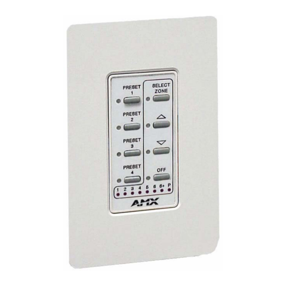
Product Information PRO-DP8 Overlay FIG. 1 shows a standard PRO-DP8 overlay. There are no numbers or labels screened on a standard blank overlay. The buttons and LED labels are shown here to describe their orientation. Custom engraved overlays are available on request. Presets 1-4 SELECT Select... -
Page 8: Presets, Channels And Zones
Product Information PRO-DP8 Pushbuttons and LEDs (Cont.) LEDs: Channel LEDs (1-6) Shows the channel (1-6, 7-18, or 13-18) that is currently selected, depend- ing on the DIP switch offset setting. See the Using Switches 1, 2 and 3 to Set Button Offset Values section on page 16 for more information. Program (P) LED Lights when the panel is Program mode, allowing you to program presets. -
Page 9: Packs
Product Information Packs Packs refer to the Dimmer Control Cards (such as the RDD-DM4/DM6) and/or Integrated Dimmer Modules (such as the RDC-DC/PDC). Each LED on the PRO-DP8 zone/channel LED indicator represents one lighting channel/zone. The PRO-DP8 controls up to 3 Packs; each individual Pack housing up to 6 lighting channels. Each Pack is connected to the PRO-DP8 via PROlink cable. -
Page 10: Sample Product Application
Product Information Sample Product Application You can use the PRO-DP8 with Radia Dimmer Packs to control lighting zones. The PRO-DP8 can control up to three Packs. FIG. 2 shows an equipment configuration model using multiple PRO- DP8 panels with a PROlink connection to two dimmer control cards. Controlled Controlled lighting... - Page 11 Product Information PRO-DP8 Decor 8-Button Wall Panel...
-
Page 12: Wiring And Installation
Wiring and Installation Wiring and Installation Preparing the PRO-DP8 and Dimmer Control Cards Assigning Pack numbers on the dimmer control cards Each dimmer card in the system must have its own unique PROlink device number, or Pack number. The Pack number is assigned via the PROLink DIP switch (SW2) on the dimmer control cards: 1. -
Page 13: Wiring The Pro-Dp8
Wiring and Installation 3. Change DIP switches 4 and 5 to match those values listed in the following table for the number of desired Packs (1-3). DIP Switch Settings for 1, 2 or 3 Packs DIP Switch 4 DIP Switch 5 Pack 1-3 Result Pack 1 ONLY... -
Page 14: Using A Prolink 4-Pin Connector With An External 12 Vdc Power Supply
GND wire on the PROlink connector when using a 12 VDC power supply. While AMX recommends installing a maximum of three PRO-DP8 panels per Pack, the actual maximum number of panels allowed per Pack is a function of power and distance between the two. -
Page 15: Prolink Status Led
Wiring and Installation 12 VDC power supply PWR (+) GND (-) Pack 2 PRO-DP8 Pack 1 FIG. 2 PROlink wiring diagram using an external 12 VDC power supply Do not connect the PWR wire to the PROlink connector’s PWR (+) terminal on the control system side of the connector. -
Page 16: Phasing
Pack numbers on the dimmer control cards section on page 7 for details. Mounting Procedures FIG. 3 shows the podium mounting dimensions for the PRO-DP8. AMX recommends mounting the PRO-DP8 in a standard one-gang wallbox with a minimum internal clearance of 2-5/8" x 1-3/4" x 1-5/8"... -
Page 17: Troubleshooting
Wiring and Installation Troubleshooting The following table gives solutions to the most common installation problems. Solutions to Common Installation Problems Problem Resolution Presets fade erratically. Check phasing. Panel LED stays on. Check the PROlink wiring, Pack number, and dimmer Pack settings. Cannot select zones 1 - 12. -
Page 18: Sample Wiring Diagram
Wiring and Installation Sample Wiring Diagram FIG. 4 shows a sample equipment wiring diagram using two Radia Lighting Dimmers and three PRO-DP8 wall panels. This illustration shows the two packs wired to two 120 VAC single-phase 20A breakers. 120 VAC 1 breaker A neutral neutral... - Page 19 Wiring and Installation PRO-DP8 Decor 8-Button Wall Panel...
-
Page 20: Dip Switch Configuration
DIP Switch Configuration DIP Switch Configuration This section describes the functionality associated with the various DIP switch settings available on the PRO-DP8 panel. These switches determine the front panel functions and should not be thought of as user accessible. DIP Switch Functions (1-8) The panel functions are set by the configuration of the DIP switch, located on the back of PRO-DP8 panel. -
Page 21: Using Switches 1, 2 And 3 To Set Button Offset Values
DIP Switch Configuration Using Switches 1, 2 and 3 to Set Button Offset Values The default setting for the DIP switch is all off. Thus, by default, there is no offset assigned to the panel pushbuttons (1-8). Use DIP switches 1-3 to set offsets by factors of four, as shown in the following table. -
Page 22: Using Switch 6 To Offset The Off Button (Pushbutton 8)
DIP Switch Configuration Pack Offsets for DIP Switches 4, 5, and Associated Channels Preset Offset DIP switch 4 DIP switch 5 Channels Pack 1 ONLY 1 - 6 Packs 1 & 2 1 - 12 Pack 2 ONLY 7 - 12 Packs 2 &... -
Page 23: Using Switch 7 To Enable Either Preset Recall Mode, Or Zone Select/Preset Ramping
DIP Switch Configuration Using Switch 7 to Enable Either Preset Recall mode, or Zone Select/Preset Ramping Panel pushbutton 5 (Select buttons) has two possible functions, depending on the setting of DIP switch 7. DIP switch 7 enables/disables the panel’s ability to select zones, or recall presets. Set switch 7 to Off (factory default setting) to enable Zone Select mode, and allow ramping of light levels. -
Page 24: Panel Programming/Operation
Panel Programming/Operation Panel Programming/Operation Program Mode The panel must be in Program mode in order to do any programming. To enter Program mode, DIP switch 8 must be set to Off (its default setting). To enter Program mode, press the Up and Down buttons (pushbuttons 6 and 7) simultaneously for 2 seconds. -
Page 25: Setting And Changing Fade Times
Panel Programming/Operation Setting and changing fade times 1. Press the Preset button where the new ramp time will be stored. 2. Enter Program mode (indicated by the P LED). 3. Set the fade time by pressing and holding a Preset button for the amount of time you want the fade to occur (the fade is from a currently active Preset level to the next active level). - Page 26 Panel Programming/Operation PRO-DP8 Decor 8-Button Wall Panel...
- Page 27 ATLANTA • BOSTON • CHICAGO • CLEVELAND • DALLAS • DENVER • INDIANAPOLIS • LOS ANGELES • MINNEAPOLIS • PHILADELPHIA • PHOENIX • PORTLAND • SPOKANE • TAMPA 3000 RESEARCH DRIVE, RICHARDSON, TX 75082 USA • 800.222.0193 • 469.624.8000 • 469-624-7153 fax • 800.932.6993 technical support • www.amx.com...
Need help?
Do you have a question about the PRO-DP8 DECOR PROLINK FLUSH MOUNT KEYPAD PANEL and is the answer not in the manual?
Questions and answers